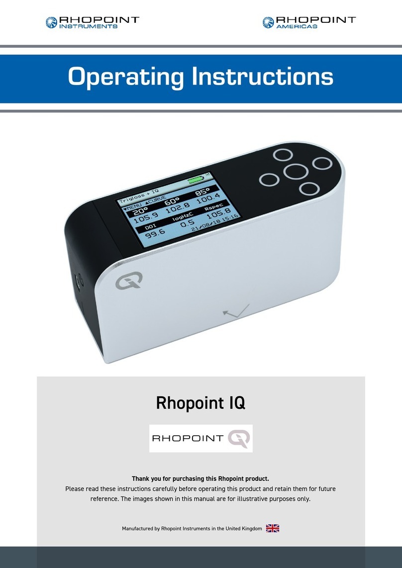
Rhopoint IQ User manual

Thank you for purchasing this Rhopoint product.
Please read these instructions carefully before operating this product and retain them for
future reference.
The images shown in this manual are for illustrative purposes only.
English
Operating Instructions

1
This instruction manual contains important information about the setup and use of
your Rhopoint IQ™. It is essential that the contents be read before powering up and
operating the instrument.
If this instrument is passed to other users you must ensure that the instruction
manual is supplied with the instrument. If you have any questions or require
additional information about the Rhopoint IQ™ please contact the Rhopoint
Authorised Distributor for your region.
The technology and components used in the device are based on state-of-the art
optic and electronics. As part of Rhopoint Instruments commitment to continually
improving the technologies used in their products, they reserve the right to change
information included in this document without prior notice.
© Copyright 2013 Rhopoint Instruments Ltd. All Rights Reserved.
Rhopoint IQ™ and Rhopoint™ are registered trademarks of Rhopoint Instruments
Ltd. in the UK and other countries.
Other product and company names mentioned herein may be trademarks of their
respective owner.
No portion of the software, documentation or other accompanying materials may be
translated, modified, reproduced, copied or otherwise duplicated (with the exception
of a backup copy), or distributed to a third party, without prior written authorization
from Rhopoint Instruments Ltd.
Rhopoint Instruments Ltd.
12 Beeching Road,
Bexhill-on-Sea,
TN39 3LG
United Kingdom
Tel: +44 (0)1424 214291
Fax: +44 (0)1424 730600
Email: sales@rhopointinstruments.com
Website: www.rhopointinstruments.com
Revision B
June 2013

2
Contents
Storage and Handling 3
About the Rhopoint IQ 4
Accessories 5
Optional items 5
Functional overview 6
Power 7
Switching on the unit 7
Operation 8
Menu Screen 11
Batching Options 12
Setup Screen 13
Data Screen 14
Calibration Screen 15
Measurement Screen 16
Control Screen 17
Instrument Setup Screen 22
Maintenance Screen 23
About Screen 24
Notes 25
Appearance Theory 26
Rhopoint IQ Glossmeter & Goniophotometer 26
Why is reflected appearance important? 27
Disadvantages of standard gloss measurement 28
Gloss 29
Haze 30
Measuring Haze with the Rhopoint IQ 31
Distinctness Of Image (DOI) 32
Reflected Image Quality (RIQ) 33
RSpec- Peak Specular Reflectance 34
Goniophotometric Profile 35
Calculating Gloss, Haze, RSpec and DOI from a Goniophotometric Profile 36
Technical Specification 37
Instrument Specification 38

3
Storage and Handling
•This instrument contains precision optics and electronics. You should avoid
knocking or dropping the device as the resulting impact could cause serious
damage.
•In some circumstances the optical components in the instrument could
become misted as a consequence of temperature change. It is
recommended that the instrument is not used until it has stabilised to
ambient temperature.
•Ensure that the instrument is not exposed to moisture, chemicals or to any
corrosive vapours.
•Do not interfere or place any objects inside the measuring aperture as
damage to the measuring system could occur.
•The instrument housing and screen are normally resistant to a variety of
solvents however it is not possible to guarantee resistance to all chemicals,
therefore the surfaces of the instrument should only be cleaned using a soft,
moist cloth.
•Prevent exposure of the instrument to direct sunlight for prolonged periods
and to continuous humidity and condensation.

4
About the Rhopoint IQ
The Rhopoint IQ is an advanced measuring instrument used to quantify the quality
of surface appearance.
Unlike a standard glossmeter the IQ has the unique capability of measuring and
detecting quality problems caused by microscopic texture in the surface that cause
haze and orange peel effects which lead to poor Distinctness Of Image (DOI),
These factors can seriously affect the visual impact and reflective quality of many
coated, painted and polished surfaces. By measuring the quality of the reflected
image it accurately profiles how light is reflected from a surface.
The instrument uses a standard optical configuration at 60°and 85°to measure the
gloss of matt and semi-gloss finishes.
However at 20°the IQ uses a diode array to measure the distribution of the
reflected light at +/- 7.25°from the specular angle of reflection in steps of 0.02832°.
This technology allows the instrument to calculate Gloss, Haze, DOI, RIQ and
RSpec providing the user with a complete analysis of the reflective quality of the
surface. Definitions of each of the parameters measured by the IQ can be found in
the section “Appearance Theory” detailed later in this manual.

5
Accessories
The instrument is supplied as a standard package complete with all accessories
required to calibrate and recharge the unit including:-
Rhopoint IQ 20/60 or 20/60/85 Glossmeter / Goniophotometer
ISO 17025 / UKAS / BAM traceable high gloss calibration tile including certificate
Cleaning cloth for calibration tile
BAM traceable instrument certificate
Mains Charger with four selectable mains input connectors (UK / Europe / US /
Australia)
USB PC cable
Quick Start Operating Instructions
Protective instrument carry case
Optional items
ISO 17025 / UKAS / BAM traceable mirror gloss calibration tile including certificate

6
Functional overview
The instrument is controlled by pressing the relevant touch sensitive button.
Functionality is dependent on whether the instrument is in menu or operate mode
as detailed in the operation sections that follow.
Label No. Function
1 On / Off Button
2 High Resolution Graphic Display
3 Up/Down/Left/Right Buttons
4 Operate / Enter Button
5 Calibration Tile (magnetised)
6 Charger Input Connector
7 USB Connector
3
5
7
4
1
2
6

7
Power
The Rhopoint IQ is powered by an integrated high capacity lithium ion cell.
Fully charged the instrument will operate continuously for >17 Hours or >20,000
readings.
A mains powered fast charger is provided with the unit, this will fully charge the unit
when connected to the units charger input (6) in under 3 hours. The IQ can be operated
with the charger plugged in.
Alternatively the Rhopoint IQ can be powered and charged using the USB port (7),
however due to the lower current available from most USB devices, the charge time will
be a minimum of 6 hours.
Charging times will be longer if the instrument is operated during charging.
Lithium ION cells do not suffer from “memory effects” so it will not reduce the life of the
battery if the fast charger or USB is used top up the battery between readings.
Switching on the unit
To switch on the unit touch the On/Off button located between the USB and charging
sockets.
The instrument will display the Rhopoint IQ logo and then enter into the home screen
displaying measurement parameters according to the instruments default settings or
those previously configured.
Similarly the instrument is powered off by pressing the On/Off button for three seconds.

8
Operation
With the unit switched on and initialised the instrument will display the home screen
as shown below.
In this mode, measurements can be made by simply pressing the operate button (4)
on the instruments keypad.
Should the Auto Calibration option be set to ON in the settings menu (detailed later
in the Instrument Settings section of this manual) a dialogue box will appear when
the operate button is pressed as shown below
Two options are available: either to “Calibrate” the instrument on the calibration tile
before making the measurement or to “Measure” without performing a calibration.
Using the Left/ Right (3) and Enter (4) buttons on the keypad the required option
can be selected.
By selecting “Calibrate” the instrument will perform a calibration and display a
confirmation dialogue box when completed. Selecting the “Confirm” option will save
the calibration information to the instruments memory, which will also be confirmed
by the calibration tile Gloss and IQ readings appearing on the instruments display.
Alternatively if “Cancel” is selected the display will return to the home screen.
By selecting “Measure” the instrument will perform a measurement and after 3 -4
seconds display the results.

9
Operation
Pressing the Up (3) button in the home screen will access the graph screen.
The goniophotometric profile and data for the last 20°measurement is displayed.
Measurements can be taken whilst in this screen and the display will be updated.
Pressing the Left button returns the display to the home screen.
Pressing the Right button in the home screen will access the gloss statistics screen
for the current batch for all three angles. Measurements can be taken whilst in this
screen and the statistics will be updated.

10
Operation
Pressing the Down (3) button the screen changes to display IQ Statistics.
Pressing the Left button returns the display to the home screen.
Pressing the Right button in the IQ statistics screen will access the gloss graph
screen providing a graphical representation of the statistics data. This same screen
is available for gloss statistics when in the Gloss statistics screen.
Pressing the Up / Down buttons IQ data can be displayed either all together or
individually. Pressing the Up button in the IQ graph screen accesses the Gloss
graph screen. Measurements can be taken whilst in this screen and the graph will
be updated after each reading.
Pressing the Left button returns the display to the statistics screen.
Pressing the Right button the instrument returns the display to the home screen.

11
Menu Screen
The Menu Screen is used for quick access to often used options. Pressing the Up
and Down buttons navigates through the options, pressing the Enter button selects
that option.
Selectable settings in the menu screen are:-
Memory – Set to ON, enables storage and batching of measurement results.
The amount of available storage memory is also displayed.
Set to OFF – disables result storage.
With Memory ON:
Delete Last Reading – Delete last measurement, no. of measurements and statistics
data updated to previous values.
Start New Batch – Start new batch of readings, Batch name is incremented by 1.
Clear Current Batch – Delete entire batch of measurements for current batch.
Delete All Batches – Delete all batches and measurements stored.
Batch Name – Default name is BATCH, a maximum of 8 user defined batch names can
be used as detailed in the “Batching Options” section.
Calibrate Instrument – Perform a calibration of the instrument as detailed under
“Operation”.
Switch Off – Turn off the instrument.
Pressing the Left button returns the display to the home screen.
Pressing the Right button will access the Setup screen.

12
Batching Options
The batching feature allows the user to group measurements together in batches. Each
batch has associated statistics; the data for each batch can be accessed by connecting
the instrument to a PC/MAC.
The current batch name is displayed on the home screen in the bottom left corner, the
sample number within that batch is shown in the top right of the screen indicated with
n=(sample number).
A new batch is started using the Start New Batch option in either the Menu screen or
the Data menu, note that the batch name will increment as will the ‘n’ indicator.
The current batch can be cleared in the either the Menu screen or the Data Menu, the
batch name will remain the same but the ‘n’ indicator will reset to zero.
Auto batch size is user defined using the Auto Batch option in the Data Menu. When the
number of readings in the current batch reach the number set by the user the
instrument will automatically increment the batch name and set the ‘n’ indicator to zero.
Viewing Batch Data
To access the stored batch information connect the instrument to a PC/MAC using the
USB data cable supplied.
A new device name “IQ-METER” can be viewed and accessed via “MY COMPUTER”,
in this device open the DATA folder. This folder contains subfolders which contain the
data for each individual saved batch. Each reading is saved as an individual comma
separated value (.csv) that contains Gloss, Haze, DOI/RIQ, RSpec, Time and Date of
Reading, Serial Number and Full Goniophotometric data for all 512 diode elements.
Each reading also contains the statistics for the batch up to and including that reading.
To access the STATISTICS for the whole batch, the last reading in the batch should be
examined.
User Defined Batch Names
Batch names are user definable. With the instrument connected to a PC/MAC, open the
folder named “CONFIG”. Within this folder there is a document named “batches”.
This is a .csv file that can be opened in Notepad, Excel or Wordpad.
User defined names should be saved in this document each name listed on a separate
line. Ensure that the final line is terminated with a carriage return.
The format of these names should only contain letters, no numbers, spaces or other
characters can be used.
Once completed save the file then switch the instrument off and on again to initialize the
new batch names.

13
Setup Screen
The Setup Screen is used to customise the instrument to the user’s preference.
Pressing the Up and Down buttons navigates through the options, pressing the Enter
button selects that option.
Data and Batch Menu - Batch / Data options (See Data & Batch Menu Screen)
Calibration Menu - Calibration options (See Calibration Menu Screen)
Measurement Menu - Geometry setup (See Measurement Menu Screen)
Control Menu - Bluetooth setup (See Control Menu Screen)
Instrument Setup - Language, Date / Time and Power options (Setup Menu Screen)
Factory Menu - Pin locked menu options for Rhopoint authorised service centres
Pressing the Left button returns the display to the home screen.

14
Data Screen
The Data Screen is similar in functionality to that of the menu screen but also allows the
selection and setting of the Auto Batch size.
By selecting Auto Batch to ON the batch size can be selected between 1 - 999 by
pressing the Left and Right buttons to select the relevant digit and the Up and Down
buttons to increment / decrement the value. Pressing the Enter button saves the batch
size.
If Batch names have been user defined, as detailed under Batching Options, selection
of the Batch Name required is achieved by repeatedly pressing the Enter button with
Batch Name selected.
Pressing the Left button returns the display to the home screen.

15
Calibration Screen
The Calibration Screen is used to setup the instrument calibration to the user’s
preference. Pressing the Up and Down buttons navigates through the options, pressing
the Enter button selects that option.
Selectable settings in the Calibration screen are:-
Calibrate instrument - Performs an instant calibration of the instrument; a dialogue box
being displayed upon completion to either “Cancel” or “Confirm”.
Auto Calibration - Set to ON, a dialogue box appears each time a measurement is
taken as detailed under Operation.
Set to OFF, the dialogue box is disabled; measurements are made.
Calibrate to - Set to Black - a traceable gloss tile is used as the calibration standard
Set to Mirror - a traceable mirror tile is used as the calibration standard
Tile Value 20, 60, 85 - Set the calibration values for either standard being used for
calibration. Pressing the Enter button selects the value. Pressing the Left and Right
buttons selects the relevant digit and the Up and Down buttons increment / decrement
the value. Pressing the Enter button again saves the value.
Error Detection - Set to ON the instrument detects the condition of the calibration
standard being used. If there are fingermarks or debris which cause it to fall outside the
value set in Haze Tolerance an error message is displayed before calibration requesting
that the tile be checked for cleanliness.
Set to OFF – Error detection is disabled, calibration is permitted
irrespective of calibration standard condition.
Haze Tolerance - Set the tolerance for the standard being used for calibration.
An ideal calibration standard should have zero haze, therefore setting this value
anywhere between 0 – 9.9 defines the acceptable pass band. Pressing the Enter button
selects the value. Pressing the Left and Right buttons selects the relevant digit and the
Up and Down buttons increment / decrement the value. Pressing the Enter button again
saves the value. Pressing the Left button returns the display to the home screen.

16
Measurement Screen
The Measurement Screen is used to configure the instruments measurement
parameters to the user’s preference. Pressing the Up and Down buttons navigates
through the options, pressing the Enter button selects that option.
Selectable settings in the Measurement screen are:-
Auto Measure – Enables or disables automatic measurement mode, used for
monitoring surfaces for changes over a period of time. Pressing the Enter button selects
the required measurement frequency of either 2, 5 or 10 seconds. When auto measure
mode is activated a dialogue box is displayed after the Enter button is pressed and
before the beginning of the measurement sequence indicating that it is activated. To
stop auto measure simply press the Enter button once again at any time during the
sequence.
Range – Selects gloss measuring range to:
Auto – Full range
Black – Standard gloss scale
Mirror - Extended scale for highly reflective materials, polished metals, requires
calibration using Mirror standard.
IQ – Selects IQ information to be either displayed (ON) or not displayed (OFF) on
screen
DOI – Selects either standard DOI (Distinctness of Image) or enhanced RIQ (Reflected
Image Quality) scale, details of which can be found in the Appearance Theory section of
this manual.
Haze – Selects either Haze or logHaze (a more sensitive measurement)
Geometry – Select the angle(s) required for measurement either:
20, 60, 85 individually
20/60 Dual mode
20/60/85 Tri mode
Pressing the Left button returns the display to the home screen.

17
Control Screen
The Control Screen is used to configure the instruments Bluetooth parameters to the
user’s preference. Pressing the Up and Down buttons navigates through the options,
pressing the Enter button selects that option.
Enable Remote Control is not presently user configurable
Selectable settings in the Control screen are:-
Bluetooth – Enables or disables Bluetooth
Bluetooth Mode – Selects Bluetooth data mode:
RC – Not currently used (for future use)
Data – Basic data transfer mode (transmits On-Screen Parameters)
Data + - Extended data mode (transmits all goniophotometric data)
Pressing the Left button returns the display to the home screen.
Bluetooth Communication and Pairing
The Rhopoint IQ has a Bluetooth function that allows readings to be instantly
transmitted to a compatible PC.
20/60/85°Gloss, Haze + Log Haze, DOI/RIQ, RSPEC, Goniophotometric
information, instrument serial number and service/calibration data can be instantly
accessed by many PC applications including Excel, Word, Wordpad, OpenOffice or
SPC packages.

18
Pairing Procedure
1.Switch on the Rhopoint IQ.
2.The Bluetooth icon must be visible to allow pairing.
3.If the Bluetooth icon is not visible, enable it
as detailed in Control Screen.
Ensure that Bluetooth mode is set to either
Data or Data+
4.In Windows, go to START menu and select “Devices and
Printers.”
5. In Devices and Printers screen Click
"Add a device"

19
6. Windows will now search for available Bluetooth devices,
double click on the icon that corresponds to the IQ
instrument.
7:Click "Enter the devices pairing code"
in the “Add a device” screen.
8:Enter the pairing code
"0000".
Make sure the IQ remains
switched on throughout
this process, to disable or
extend auto power off refer
to instructions detailed in
Instrument Setup Screen
that follow.
Table of contents
Other Rhopoint Measuring Instrument manuals
Rhopoint
Rhopoint Optimap PSD User manual

Rhopoint
Rhopoint NOVO-GLOSS IQ User manual

Rhopoint
Rhopoint IQ 20/60 User manual

Rhopoint
Rhopoint NOVO-GLOSS User manual

Rhopoint
Rhopoint Novo-Shade Duo+ User manual

Rhopoint
Rhopoint Hanatek Novo-Haze TX User manual
Rhopoint
Rhopoint Novo-Gloss 20/60/75 User manual

Rhopoint
Rhopoint NOVO-GLOSS Flex 60 User manual

Rhopoint
Rhopoint Optimap3 PSD User manual

Rhopoint
Rhopoint NOVO-GLOSS 60 User manual