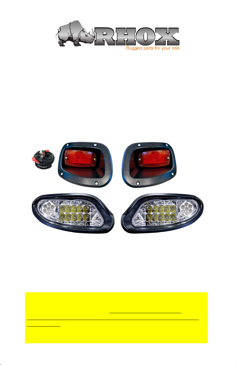
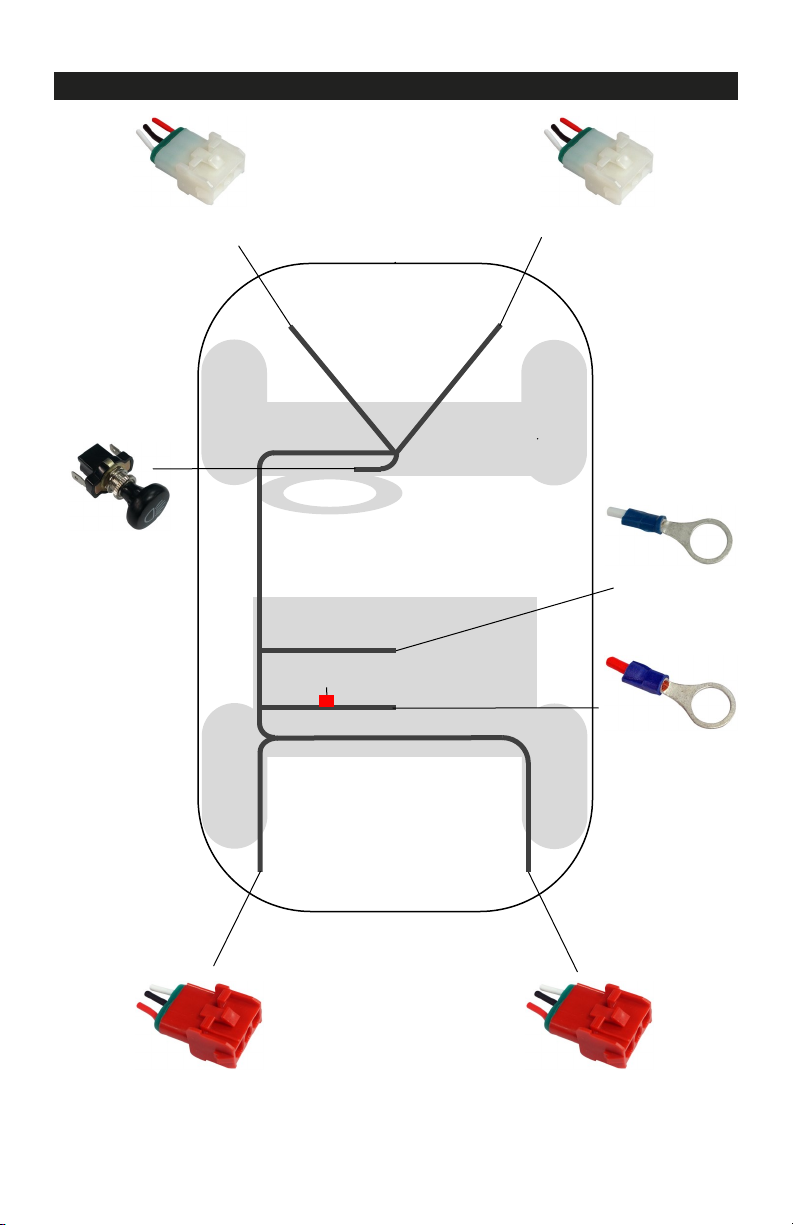
Headlight & Taillight Preparation
Headlight Preparation
1. Cut out the headlight template following the guidelines.
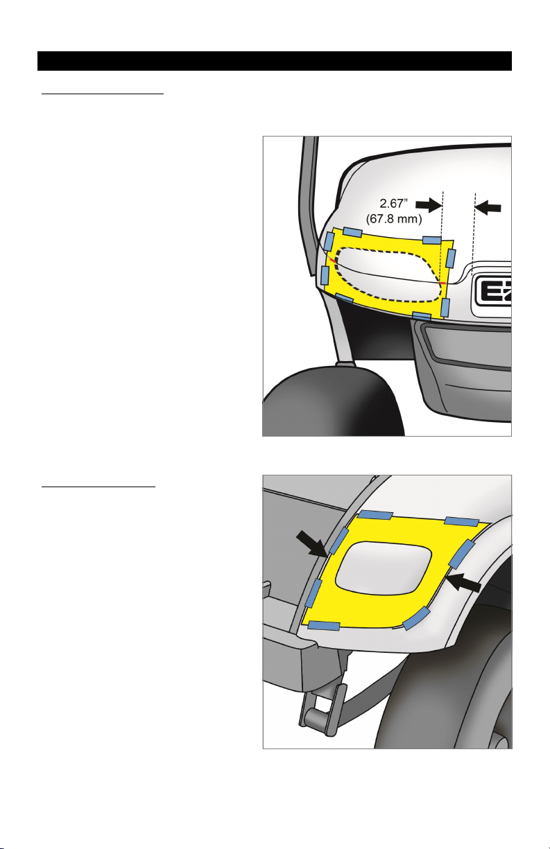
2. Place the template on the passenger
side front cowl and align it with the
cowl mold lines and emblem. Secure
with painter’s tape.
3. Trace the inside contour of the
template using a marking device.
NOTE: To prevent chipped paint on
a painted cowl, tape over the drawn
line and redraw over the tape using
the template.
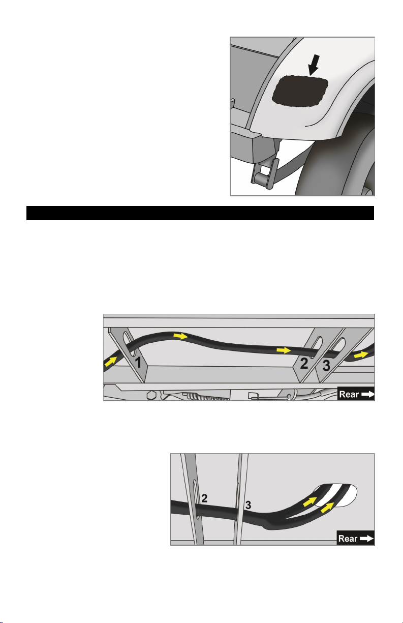
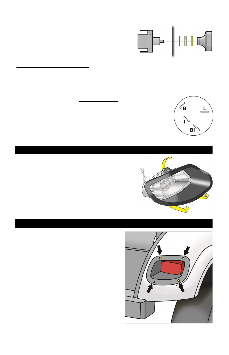
4. Using a jig saw or rotary tool, cut out
the INSIDE of the marked area.
Test fit the headlight and make any
adjustments before removing the
tape. Once the light fits, remove the
tape and sand any rough edges.
5. Flip the template over and repeat
Steps 2-4 for the driver’s side.
Taillight Preparation
1. Cut out the included taillight
template following the guidelines.
2. Use painter’s tape to tape the
template to the passenger side rear
body of the cart. Align the template
with the body lines as indicated on
the template.
3. Use a marking device to trace the
inside contour of the template onto
the body.
NOTE: To prevent the paint from
chipping, lay painter’s tape down
first and trace over the tape.
Page 4