RIB ABP1001 User manual

PARK LIGHT
Cod. ABP1001
Scarica questo manuale sul tuo cellulare
Téléchargez ce manuel sur votre mobile
Download this manual on your mobile
Laden Sie dieses Handbuch auf Ihr Handy herunter
Descarga este manual en tu móvil

1
4
7
13
2
5
8
14
3
6
9
12
10 11

S L
T
L (mm) T (mm) S (mm)
3.154 3.545 196
4.154 4.585 216
5.154 5.585 236
6.154 6.605 256
IL = Lunghezza asta 3, 4, 5, 6 mt come fornita di fabbrica
T = Lunghezza Totale tubo led (N.B.:effettuare taglio a misura in corrispondenza
della linea bianca tratteggiata)
S = Lunghezza tubo led da ripiegare all’interno dell’asta
GB L = Rod length 3, 4, 5, 6 m as supplied from factory
T = Total length of the LED tube (perform cut to size along the white dashed line)
S = Length of the LED tube to fold back inside the rod
FL = Longueur de la barre 3, 4, 5, 6 mètres comme fournie à l’usine
T = Longueur totale du tube led (effectuer la découpe à la mesure en correspondance
de la ligne blanche en tirets)
S = Longueur du tube led à replier à l’intérieur de la barre
DL = 3, 4, 5, 6 m Schrankenänge wie nach Lieferumfang
T = Gesamtlänge LED-Schlauch (Schnitt nach Maß entsprechend der weiß
gestrichelten Linie ausführen)
S = Länge des LED-Schlauchs, der in der Schranke gefaltet werden muss
EL = Longitud varilla 3, 4, 5, 6 m según se entrega desde la fábrica
T = Longitud total del tubo de led (efectuar el corte a medida a la altura de la línea
blanca punteada)
S = Longitud del tubo de led a plegar dentro de la varilla
I1-2 Assemblare il tubo
led inserendo la guaina diametro
14 sul tubo led
3 Prendere ora il connettore
maschio in dotazione……..
4-5…….E inseritelo con forza
nel tubo led in riferimento ai 2
conduttori che alimentano i led
6 Dopo averlo inserito controllate
che il diametro del connettore
maschio corrisponda al diametro
del tubo led.
7-8 Inserire ora il tubo led con
connettore maschio nel connettore
femmina con cavo di alimentazione
in dotazione
9 Avvicinate ora la guaina diametro
14 al connettore
10 Togliere il tappo anteriore asta
utilizzando un cacciavite a croce.
11-12 Togliere completamente
la copertura led arancione
sollevandola dal profilo dell’asta
dal lato del tappo anteriore.
13-14 Tagliate il tubo led lungo
il tratteggio alla quota indicata in
tabella.
GB 1-2 Assemble the LED
tube by inserting the sheath with
diametre 14 onto the LED tube
3 Now take the male connector
supplied……..
4-5…….And insert it firmly into
the LED tube in relation to the 2
conductors that power the LEDs
6 Once inserted, check that the
diameter of the male connector
matches the diameter of the LED
tube.
7-8 Now insert the LED tube with
male connector into the female
connector using the power cable
supplied
9 Now move the sheath diameter
14 closer to the connector
10 Remove the front cap of the rod
using a cross-head screwdriver.
11-12 Remove completely the
orange LED cover by lifting it from
the beam profile from the front cap
end.
13-14 Cut the LED tube along the
dashed line, as indicated in the
table.
F1-2 Assembler le tube led
en insérant la gaine de diamètre
14 sur le tube led
3 Prendre maintenant le connecteur
mâle fourni en dotation……..
4-5…….Et insérez-le avec force
dans le tube led en correspondance
des 2 fils qui alimentent les led
6 Après l’avoir inséré, contrôlez
que le diamètre du connecteur
mâle correspond au diamètre du
tube led.
7-8 Introduire maintenant le tube
led avec le connecteur mâle dans
le connecteur femelle avec le câble
d’alimentation fourni en dotation
9 Rapprocher maintenant la gaine
de diamètre 14 du connecteur
10 Enlever le bouchon avant de
la barre en utilisant un tournevis
cruciforme.
11-12 Enlever complètement la
protection del orange vif en la
soulevant du profil de la barre du
côté du bouchon avant.
13-14 Coupez le tube led long des
tirets à la hauteur indiquée dans le
tableau.
D1-2 Montieren Sie den
Schlauch, indem Sie die Hülse mit
Durchmesser 14 auf den LED-
Schlauch aufsetzen
3 Nehmen Sie nun den mitgelie-
ferten männlichen Stecker ........
4-5 ....... und stecken Sie ihn fest
in den LED-Schlauch, entspre-
chend der 2 Leiter, die die LEDs
speisen.
6 Nachdem Sie ihn eingefügt
haben, sichern Sie ab, dass der
Durchmesser des männlichen
Steckers dem Durchmesser der
LED-Röhre entspricht.
7-8 Fügen Sie nun den LED-
Schlauch mit Stecker in die mitge-
lieferte Buchse mit Netzkabel
9 Nähern Sie nun die Hülse mit
Durchmesser 14 der Buchse
10 Entfernen Sie den Frontdeckel
der Schranke mit einem Kreuz-
schlitzschraubendreher.
11-12 Entfernen Sie die orangefar-
bene LED-Abdeckung vollständig ,
indem Sie sie vom Schrankenpro-
fil von der Seite des Frontdeckels
her hervorheben.
13-14 Durchschneiden Sie den
LED-Schlauch entlang der gestri-
chelten Linie an der in der Tabelle
angegebenen Höhe.
E1-2 Ensamblar el tubo de
led introduciendo la vaina con un
diámetro 14 en el tubo de led
3 Ahora coger el conector macho
que se entrega……..
4-5…….E introducirlo firmemente
en el tubo de led en referencia a
los 2 conductores que alimentan
los led
6 Después de haberlo introducido
controlar que el diámetro del
conector macho se corresponda
con el diámetro del tubo de led.
7-8 Ahora introducir el tubo de
led con el conector macho en el
conector hembra con el cable de
alimentación en dotación
9 Ahora, acercar la vaina con
diámetro 14 al conector
10 Quitar el tapón anterior de la
varilla utilizando un destornillador
de cruz.
11-12 Quitar completamente la
tapa led naranja levantándola del
perfil de la varilla por el lado del
tapón anterior.
13-14 Cortar el tubo de led a lo
largo de la línea discontinua en la
altura indicada en la tabla.
3

16 17
19
18
23
26
22
2827 29
21
15
20
24 25

I15-16 Inserite il tappo
terminale sulla punta del tubo led
17-18 Inserire il mozzo nell’albero
di traino
19-22 Applicare il cavallotto con la
piastrina di tenuta cavo led
23 Applicare il cavallotto al mozzo.
Inserire il profilo dell’asta e tirare le
viti di tenuta del cavallotto. Applicare
in riferimento all’asola passacavo
nella parte centrale del mozzo il
cavallotto adesivo fissatubo.
24 Inserire le molle di bilanciamento
e avvitare le ghiere per regolare la
tensione come indicato sul manuale.
25 Inserite ora il cavo nell’asola
presente sul mozzo porta asta.
26-27 Inserire nel foro passaggio
cavi la protezione plastica per
evitare l’usura dei cavi stessi.
28-29 Fissare, con fascetta in
dotazione, il connettore femmina
con tubo led inserito, al fissatubo
precedentemente incollato.
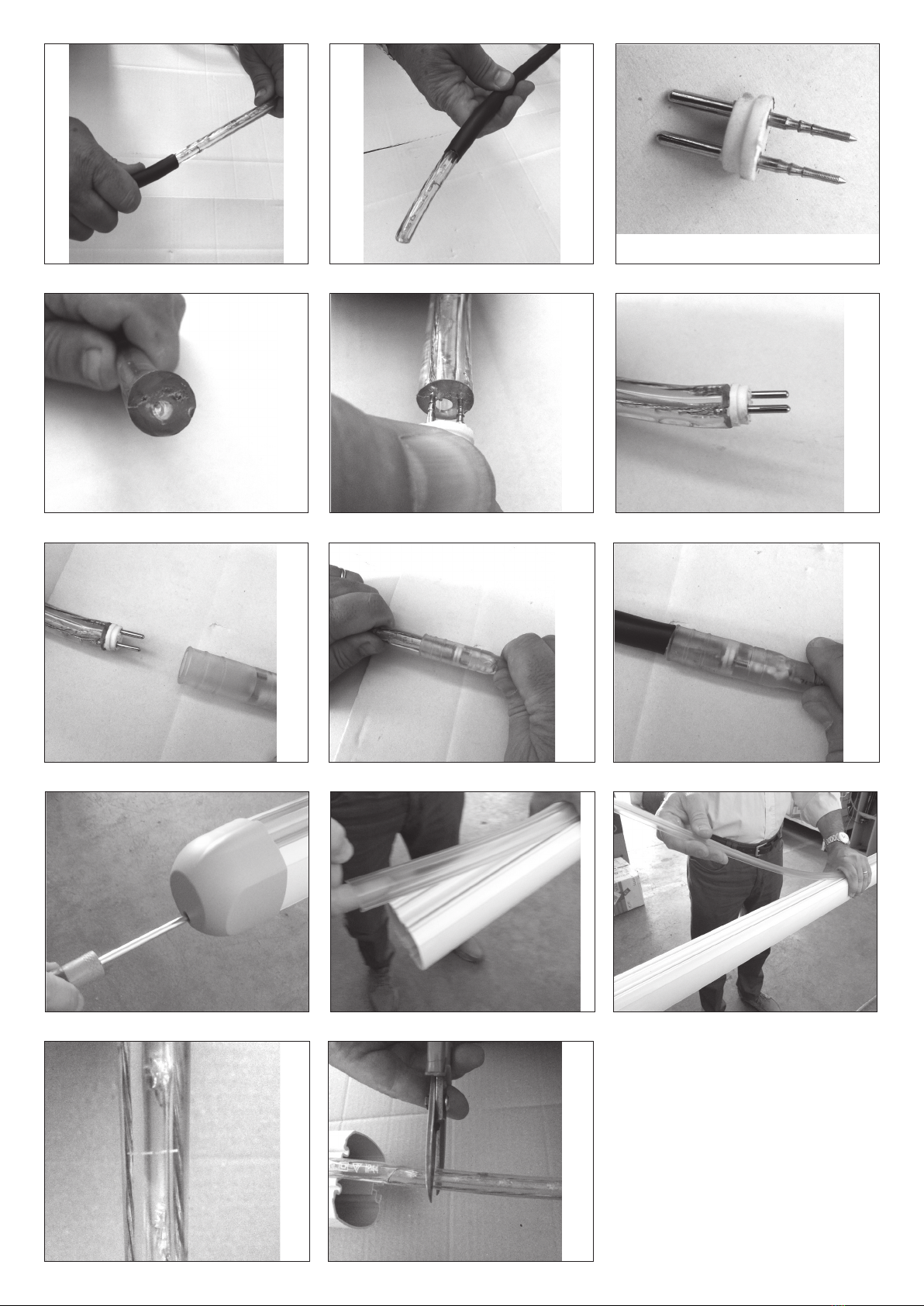
30 Sbloccare la barriera e abbassare
l’asta
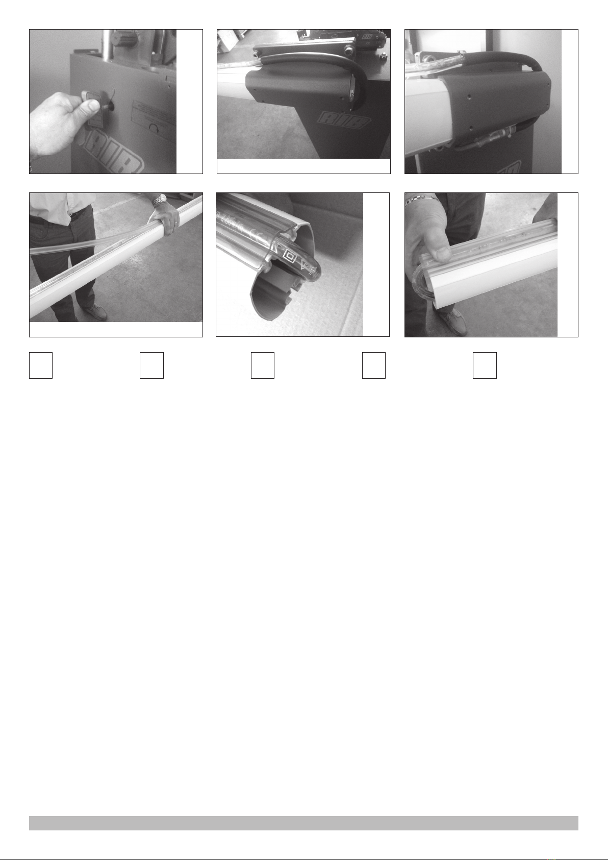
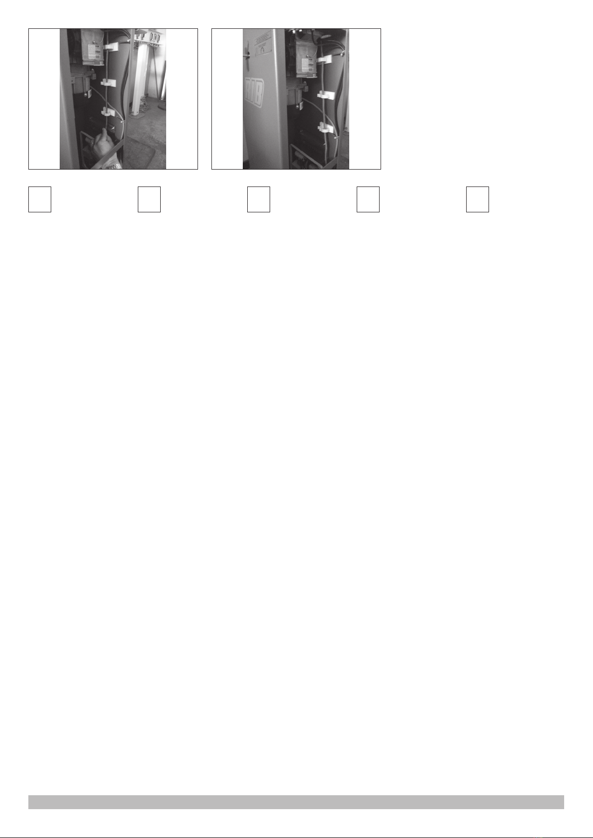
31-32 Avvolgere il tubo led attorno
al mozzo
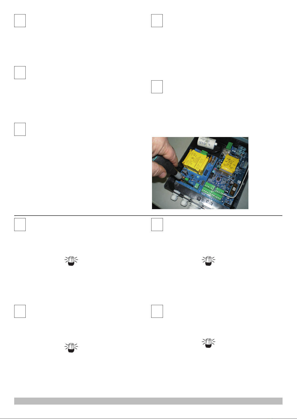
33 Appoggiate il tubo led
nell’apposita sede sull’asta
facendolo sporgere della quota S
indicata in tabella e bloccatelo con
la protezione led arancio.
34-35 In punta all’asta ripiegate il
tubo led all’interno del profilo.
GB 15-16 Insert the end cap
onto the end of the LED tube
17-18 Insert the hub into the drive
shaft
19-22 Apply the clevis with the LED
cable retaining plate
23 Apply clevis to the hub.
Insert the rod profile and pull the
retaining screws of the clevis. In
correspondence to the fairlead slot,
apply in the middle of the hub the
adhesive tube fastening.
24 Insert the balancing springs and
operate the ring nuts to adjust the
tension as indicated in the manual.
25 insert the cable into the slot
found on the rod holder hub.
26-27 Insert the plastic protective
film into the fairlead to prevent the
cable from wearing.
28-29 Use the supplied clamp to
fasten the female connector, with the
LED tube inserted, to the previously
glued adhesive tube fastening.
30 Release the barrier and lower
the rod
31-32 Wrap the led tube around the
hub.
33 Place the LED tube in its seat
within the rod, making it stick out
beyond level S indicated in the table
and lock it with the orange LED
protection.
34-35 At beam’s end fold the LED
tube within the profile.
F15-16 Insérez le bouchon
terminal sur la pointe du tube led
17-18 Insérez le moyeu dans l’arbre
de traction
19-22 Appliquer le cavalier avec la
plaque d’étanchéité du câble led
23 Appliquer le cavalier au moyeu.
Insérer le profil de la barre et tirer les
vis d’étanchéité du cavalier.
Appliquer au niveau de la fente
passe-fil, dans la partie centrale du
moyeu, le cavalier adhésif fixant le
tube.
24 Insérer les ressorts d’équilibrage
et visser les écrous pour régler la
tension comme indiqué dans la
notice.
25 Insérez maintenant le câble dans
la fente présente sur le moyeu porte-
barre.
26-27 Insérer dans le trou de
passage des câbles la protection
plastique pour éviter l’usure desdits
câbles.
28-29 Fixer, à l’aide d’un collier
fourni en dotation, le connecteur
femelle avec le tube led inséré, a le
cavalier adhésif fixant le tube.
30 Relâchez la barrière et abaisser
la tige
31-32 Enveloppez le tube led autour
du moyeu.
33 Poser le tube led dans le
logement prévu à cet effet sur la
barre en le faisant pencher de la
hauteur S indiquée dans le tableau
et bloquez-le avec la protection del
orange.
34-35 Au niveau de la pointe de la
barre, repliez le tube led à l’intérieur
du profil.
D15-16 Fügen Sie
die Endkappe auf die Spitze des
LED-Schlauches
17-18 Legen Sie die Nabe in die An-
triebswelle ein
19-22 Befestigen Sie den Gabel-
kopf mit der Kabeldichtplatte
23 Befestigen Sie den Gabelkopf an
der Radnabe. Fügen Sie das Schran-
kenprofil ein und ziehen Sie die
Halteschrauben der Gabel fest.
Befestigen Sie die selbstklebende
U-Kabelfixierung entsprechend der
Kabelöse an der Nabenmitte.
24. Legen Sie die Ausgleichsfedern
ein und schrauben Sie die Muttern
zur Spannungseinstellung wie im
Handbuch angegeben an.
25 Legen Sie das Kabel jetzt in den
auf der Stangennabe vorhandene
Öse.
26-27 Fügen Sie den Plastik-
schutz in die Kabelführungsöffnung
ein, um den Verschleiß der Kabel zu
verhindern.
28-29 Befestigen Sie die Buchse mit
LED-Schlauch mit dem mitgeliefer-
ten Befestigungsring an der zuvor
angeklebte U-Kabelfixierung
30 Lassen Sie die Schranke und
senken die Stange
31-32 Wickeln Sie die LED-Röhre
um die Nabe.
33 Legen Sie den LED-Schlauch in
den Sitz vorgesehenen Sitz auf der
Schranke, so dass er um den in
der Tabelle angegebenen Abschnitt
S hervorragt und blockieren Sie
ihn mit dem orangefarbenen LED-
Schutz.
34-35 Falten Sie den LED-Schlauch
an der Schrankenspitze im Inneren
des Profils.
E15-16 Introducir el tapón
del terminal en la punta del tubo de
led
17-18 Introducir el cubo en el eje de
arrastre
19-22 Aplicar el perno de horquilla
con el soporte del cable de led.
23 Aplicar el perno de horquilla el
cubo. Introducir el perfil de la varilla
y tirar de los tornillos de sujeción
del perno de horquilla. Colocar en
la ranura del pasacables, en la parte
central del cubo, el perno de la
horquilla adhesiva que fija el tubo.
24 Introducir los muelles de
equilibrio y colocar las abrazaderas
para regular la tensión como se
indica en el manual.
25 Introducir el cable en la ranura
presente en el cubo porta-varilla.
26-27 Introducir en el orificio de
paso de cables la protección de
plástico para evitar el desgaste de
los propios cables.
28-29 Colocar, con la abrazadera
que se entrega, el conector hembra
con tubo de led una vez introducido
la horquilla adhesiva que fija el tubo
anteriormente encolada.
30 Soltar la barrera y bajar la varilla
31-32 envolver el tubo de led
alrededor del cubo.
33 Apoyar el tubo de led en la
zona correspondiente de la varilla
haciendo que sobresalga por la
altura S indicada en la tabla y
bloqueadlo con la protección led
naranja.
34-35 En la punta de la varilla plegar
el tubo de led dentro del perfil.
30
34
32
35
31
33
5

37 38
39
47
46
43 44
40 41
42
49 50
36
45
48

I36-37 Applicate il tappo
in punta all’asta e fissatelo con
l’apposita vite.
38 Inserire il cavo di alimentazione
nel foro come da immagine
37-38 Applicare ad incastro il
blocca cavi come da immagini
41-42 Fissare poi il cavo di
alimentazione con fascetta in
dotazione nel punto indicato in
immagine
43-46 Montate il coperchio
del mozzo avvitando le 4 viti in
dotazione con una chiave a brugola
da 5.
47 Prendete gli anelli adesivi per
tenuta cavi.
48-50 Rimuovete la pellicola e
applicateli all’interno della colonna
51-52 Inserite il cavo di
alimentazione negli anelli e
collegatelo poi alla scheda PéARK
LIGHT come indicato qui di seguito.
GB 36-37 Apply the cap at
beam’s end and fasten it with the
corresponding screw.
38 Insert the power cable into the
slot, as shown in figure
37-38 Slot in the cable lock as
shown in figures
41-42 Then fasten the power
cable with the supplied clamp to
the point shown in pictures
43-46 Assemble the hub cap by
tightening the 4 screws supplied
with an Allen wrench size 5.
47 Take the adhesive rings for
cable fastening.
48-50 Remove the film and aply
them within the column.
51-52 Insert the power cable in
the rings and plug it to the PARK
LIGHT board as shown below.
F36-37 Appliquez le
bouchon à la pointe de la barre et
fixez-le avec la vis spéciale.
38 Insérer le câble d’alimentation
dans le trou comme indiqué sur
l’image
37-38 Appliquer par encastrement
le bloque-câbles comme décrit sur
les images
41-42 Fixer ensuite le câble
d’alimentation à l’aide du collier
fourni en dotation au niveau du
point indiqué sur l’image
43-46 Montez le couvercle du
moyeu en vissant les 4 vis fournies
en dotation avec une clé Allen de
5.
47 Prenez les anneaux adhésifs
pour l’étanchéité des câbles.
48-50 Enlevez la pellicule et
appliquez-les à l’intérieur de la
colonne
51-52 Insérez le câble
d’alimentation dans les anneaux
et branchez-le ensuite à la fiche
PARK LIGHT comme indiqué ici
ci-après.
D36-37 Bringen Sie den
Deckel an der Schrankenspitze an
und fixieren Sie ihn mit der
vorgesehenen Schraube.
38 Führen Sie das Netzkabel in die
Öffnung wie nach Abbildung
37-38 Fügen Sie die Kabelsperre
wie nach Abbildungen ein
41-42 Fixieren Sie dann das
Stromkabel mit mitgelieferter
Klemme am auf dem Bild auf der
linken Seite angezeigten Punkt
43-46 Montieren Sie
die Nabenkappe durch Anziehen
der 4 Schrauben mit einem
Inbusschlüssel 5.
47 Nehmen Sie die Haftringe zur
Abdichtung der Kabel.
48-50 Entfernen Sie den
Schutzfilm und befestigen Sie sie
in der Säule.
51-52 Legen Sie das
Netzkabel in die Ringe und
schließen Sie es sodann an die
PARK LIGHT Platine wie hier im
Folgenden angezeigt.
E36-37 Colocar el tapón en
punta en la varilla y fijarlo con el
tornillo correspondiente.
38 Introducir el cable de
alimentación en el orificio según
se observa en la imagen.
37-38 Colocar con encaje el
bloqueador de cables según se
observa en la imagen.
41-42 Fijar después el cable de
alimentación con la abrazadera
que se entrega en el punto
indicado en la imagen.
43-46 Colocar la tapa del cubo
atornillando los 4 tornillos que se
entregan con una llave Allen de 5.
47 Coger los anillos adhesivos
para la retención de los cables.
48-50 Quitar la película y colocarla
dentro de la columna.
51-52 Introducir el cable de
alimentación en los anillos y
conectarla después a la tarjeta
PARK LIGHT como se indica a
continuación.
5251
7

IASSEMBLAGGIO SCHEDA PARK LIGHT
Fissare la scheda PARK LIGHT utilizzando le 3 viti TCCR 3,9 x 9,5 a corredo.
COLLEGAMENTI ELETTRICI
Togliere tensione alla scheda P1.
Eseguire i collegamenti come indicato qui di seguito.
Alimentare le schede e verificare la corretta funzionalità delle opzioni scelte.
Attenzione: se il tubo led non si accende, invertire i fili connessi nel morsetto J13.
GB PARK LIGHT BOARD ASSEMBLY
Fasten the PARK LIGHT board using the 3 TCCR screws 3,9 x 9,5 supplied.
WIRING
Cut the power to the P1 board.
Perform wiring as shown below. Power the boards and make sure the chosen options
function properly.
Caution: if the LED tube does not light up,reverse the wires connected to terminal
J13.
FASSEMBLAGE DE LA FICHE PARK LIGHT
Fixer la fiche PARK LIGHT en utilisant les 3 vis TCCR 3,9 x 9,5 fournies en dotation.
BRANCHEMENTS ÉLECTRIQUES
Couper le courant au niveau de la fiche P1.
Effectuer les branchements comme indiqué ici ci-après.
Alimenter les fiches et vérifier la bonne fonctionnalité des options choisies.
Attention : si le tube led ne s’allume pas, inverser les fils branchés dans le bornier
J13.
DZUSAMMENBAU PARK LIGHT PLATINE
Befestigen Sie die PARK LIGHT Platine mit den 3 TCCR 3,9 x 9,5 Schrauben im
Lieferumfang.
ELEKTRISCHE ANSCHLÜSSE
Trennen Sie die Spannung der P1 Platine.
Stellen Sie die Verbindungen wie im Folgenden gezeigt her.
Versorgen Sie die Platinen und überprüfen Sie das korrekte Funktionieren der gewählten
Optionen.
Achtung: Wenn die LED-Röhre nicht leuchtet stellen Sie die an der Klemme J13
angeschlossenen Drähte um.
EMONTAJE DE LA TARJETA PARK LIGHT
Fijar la tarjeta PARK LIGHT utilizando los 3 tornillos TCCR 3,9 x 9,5 que se entregan.
CONEXIONES ELÉCTRICAS
Quitar la alimentación en la tarjeta P1. Realizar las conexiones como se indica a
continuación.
Alimentar las tarjetas y comprobar el correcto funcionamiento de las elecciones realizadas.
Atención: si el tubo de led no se enciende, invertir los hilos conectados en la borne
J13.
I
LIGHT INTENSITY - regolazione luminosità tubo led
OUTPUT AUX 230V - alimentazione ausiliaria 230Vac 50-60 Hz per
crepuscolare
SW1 - microinterruttori per selezione opzioni
J11 - collegamento alimentazione 230Vac 50-60 Hz
J12 - da collegare all’uscita lampeggiatore
della scheda P1. Per accendere il tubo led durante il
funzionamento della barriera.
J13 LIGHT BOOM - collegamento tubo led 24Vdc
J14 COM-SIGNAL - collegamento alla scheda P1 per accensione tubo led
solo a barriera chiusa
J15 CREPUSCOLAR CONTACT - collegamento contatto N.O. Interruttore crepuscolare
senza potenziale (contatto pulito)
GB
LIGHT INTENSITY - LED tube brightness control
OUTPUT AUX 230V - Auxiliary power supply 230Vac 50-60 Hz for Dusk to
Down Sensor
SW1 - DIP switches for options
J11 - Power Supply 230Vac 50-60 Hz
J12 - to connect on P1 card to blinker output. This
to feed led tube during barrier movement
J13 LIGHT BOOM - LED tube connection 24Vdc
J14 COM-SIGNAL - connection to the P1 board for lighting up the LED tube
only with the barrier closed
J15 CREPUSCULAR CONTACT - contact connection N.O. Potential free crepuscular
switch (dry contact)
F
LIGHT INTENSITY - réglage de la luminosité du tube led
OUTPUT AUX 230V - Alimentation auxiliaire 230Vac 50-60 Hz pour Capteur
Crèpuscolaire.
SW1 - micro-interrupteurs pour sélection des options
J11 - Alimentation 230Vac 50-60 Hz
J12 - connecter sur la carte P1 à la sortie de
clignotant. Pour alimenter le tube de LED pendant le
mouvement de la barrière
J13 LIGHT BOOM - raccordement du tube led 24Vdc
J14 COM-SIGNAL - raccordement à la fiche P1 pour allumage du tube led
seulement quand la barrière est fermée
J15 CREPUSCOLAR CONTACT - raccordement du contact N.O. Interrupteur crépusculaire
sans potentiel (contact propre)
D
LIGHT INTENSITY - Beleuchtungsregelung LED-Schlauch
OUTPUT AUX 230V - Hilfsenergie 230vac 50-60 hz für Dämmerungs-Sensor
SW1 - Mikroschalter für die Wahl von Optionen
J11 - Stromversorgung 230Vac 50-60 Hz
J12 - Um P1 Karte Blinkerausgang verbinden. Dies
ermöglicht, LED-Röhre während der Barrieren Bewegung
füttern
J13 LIGHT BOOM - 24V DC LED-Schlauch-Verbindung
J14 COM-SIGNAL - Verbindung zur P1 Platine für Einschaltung LED-Röhre
nur bei geschlossener Schranke
J15 CREPUSCOLAR CONTACT - Anschluss Kontakt N.O.
Potentialfreier Dämmerungsschalter (Trockenkontakt)
8

12
CD
34
Alimentazione
Power supply
Alimentation
Stromversorgung
Alimentación
230V ac
Alimentazione Tubo Led
LED Tube Power supply
Alimentation Tube Led
LED-Schlauch Versorgung
Alimentación Tubo de Led
24V dc
Sensore Crepuscolare optional Cod.
Optional Dusk to Dawn Sensor Code
Capteur Crépusculaire en option Réf.
Optionaler Dämmerungs-Sensor Code
Sensor crepuscular opcional Cód.
ACG1510
E
LIGHT INTENSITY - regulación luminosidad tubo de led
OUTPUT AUX 230V - Alimentación auxiliar 230vac 50-60 hz para Sensor
crepuscolar
SW1 - microinterruptores para selección opciones
J11 - Alimentación 230Vac 50-60 Hz
J12 - debe estar conectado a los terminales del
destellador de cuadro P1. Para encender el tubo de LED
durante el funcionamiento de la barrera.
J13 LIGHT BOOM - conexión tubo de led 24Vdc
J14 COM-SIGNAL - conexión a la tarjeta P1 para el encendido del tubo de led
únicamente con la barrera cerrada
J15 CREPUSCOLAR CONTACT - conexión contacto N.O. Interruptor crepuscular sin
potencial (contacto limpio)
9

ITIPI DI FUNZIONAMENTO LUCI LED
1 - Luce sempre accesa fissa
Posizionare tutti i microinterruttori su OFF
2 - Luce sempre accesa lampeggiante
Posizionare il microinterruttore 1 su ON
Nota: è possibile variare il lampeggio agendo sui microinterruttori 3 e 4 nel seguente modo:
DIP 3 DIP 4 TEMPO DI LAMPEGGIO
OFF OFF 0,5s ON/OFF
ON OFF 1s ON/OFF
ON ON 2s ON/1s OFF
OFF ON 0,2s ON/OFF
3 - Luce che si accende fissa al comando del motore
Posizionare i microinterruttori 1 e 2 su ON
Nota: obbligatorio eseguire il collegamento tra morsetti lampeggiatore della scheda P1 e
morsetti lampeggiatore della scheda PARK LIGHT.
4 - Luce che si accende lampeggiante al comando del motore
Posizionare il microinterruttore 2 su ON
Nota: obbligatorio eseguire il collegamento tra morsetti lampeggiatore della scheda P1
e morsetti lampeggiatore della scheda PARK LIGHT, inoltre è possibile variare il lampeggio
agendo sui microinterruttori 3 e 4 nel seguente modo:
DIP 3 DIP 4 TEMPO DI LAMPEGGIO
OFF OFF 0,5s ON/OFF
ON OFF 1s ON/OFF
ON ON 2s ON/1s OFF
OFF ON 0,2s ON/OFF
5 - Luce accesa fissa a barriera ferma e luce accesa lampeggiante durante il
funzionamento della barriera
Posizionare tutti i microinterruttori su OFF
Nota: obbligatorio eseguire il collegamento tra morsetti lampeggiatore della scheda P1 e
morsetti lampeggiatore della scheda PARK LIGHT, inoltre è possibile variare il lampeggio
agendo sui microinterruttori 3 e 4 nel seguente modo:
DIP 3 DIP 4 TEMPO DI LAMPEGGIO
OFF OFF 0,5s ON/OFF
ON OFF 1s ON/OFF
ON ON 2s ON/1s OFF
OFF ON 0,2s ON/OFF
6 - Luce accesa fissa o luce accesa lampeggiante solo a barriera chiusa
Posizionare il microinterruttore 6 su ON
Le funzionalità descritte ai punti 1-2 saranno funzionanti solo a barriera chiusa.
7 - Funzionamento con sensore crepuscolare (opzionale cod ACG1510)
Posizionare il microinterruttore 5 su ON
Le funzionalità descritte ai punti 1-2-3-4-5-6 saranno funzionanti solo di notte con contatto
chiuso del sensore crepuscolare.
Attenzione: la sonda crepuscolare deve essere posizionata sulla colonna in
condizione favorevole alla lettura della luce. Eseguire un foro Ø 1 cm.
CARATTERISTICHE TECNICHE
Range di temperatura -10 ÷ + 55°C
Umidità < 95% senza condensazione
Tensione di alimentazione 230 V~ ±10% o 120 V~ ±10% (a richiesta)
Frequenza 50/60 Hz
Assorbimento massimo scheda 80mA con tubo led da 6 metri
Microinterruzioni di rete 100ms
Carico massimo all’uscita LIGHT BOOM 20W a 24Vdc
GB LED LIGHTS FUNCTIONING TYPES
1 - Solid constant light
Set all DIP switches to OFF
2 - Flashing constant light
Set DIP switch 1 to ON
Note: you can adjust flashing using DIP switches 3 and 4 as follows:
DIP 3 DIP 4 FLASHING TIME
OFF OFF 0,5s ON/OFF
ON OFF 1s ON/OFF
ON ON 2s ON/1s OFF
OFF ON 0,2s ON/OFF
3 - Light that turns on solid with engine control
Set DIP switches 1 and 2 to ON
Note: you are required to connect the P1 board flash light terminals to the PARK LIGHT board
flash light terminals.
4 - Light that turns on flashing with engine control.
Set DIP switch 2 to ON
Note: you are required to connect the P1 board flash light terminals to the PARK LIGHT board
flash light terminals, and you can also adjust flashing using the DIP switches 3 and 4, as
follows:
DIP 3 DIP 4 FLASHING TIME
OFF OFF 0,5s ON/OFF
ON OFF 1s ON/OFF
ON ON 2s ON/1s OFF
OFF ON 0,2s ON/OFF
5 - Steady light on with steady barrier and flashing light on during barrier operation
Set all DIP switches to OFF
Note: you are required to connect the P1 board flash light terminals to the PARK LIGHT board
flash light terminals, and you can also adjust flashing using the DIP switches 3 e 4 as follows:
DIP 3 DIP 4 FLASHING TIME
OFF OFF 0,5s ON/OFF
ON OFF 1s ON/OFF
ON ON 2s ON/1s OFF
OFF ON 0,2s ON/OFF
6 - Steady light on or flashing light on only with barrier closed
Set DIP switch 6 to ON
The features described in paragraphs 1-2 work only when the barrier is closed.
7 - Operation with crepuscular sensor (code ACG1510 as option)
Set DIP switch 5 to ON
The features described in paragraphs 1-2-3-4-5-6 work only during the night, with closed
contact of the crepuscular sensor.
Caution: the crepuscular probe must be placed on the column in favourable
condition to detect light. Drill a hole with diameter Ø 1 cm.
TECHNICAL SPECIFICATIONS
Temperature range -10 ÷ + 55°C
Humidity < 95% without condensation
Supply voltage 230 V~ ±10% o 120 V~ ±10% (upon request)
Frequency 50/60 Hz
Maximum power consumption 80mA with 6 meters long LED tube
Interruptions in electricity supply 100ms
LIGHT BOOM outlet maximum load 20W at 24Vdc
10

FTYPES DE FONCTIONNEMENT LUMIÈRES
LED
1 - Lumière toujours allumée fixe
Régler tous les micro-interrupteurs sur OFF
2 - Lumière toujours allumée clignotante
Régler le micro-interrupteur 1 sur ON
Remarque : il est possible de varier le clignotement en agissant sur les micro-interrupteurs 3
et 4 de la manière suivante :
DIP 3 DIP 4 DURÉE DE CLIGNOTEMENT
OFF OFF 0,5s ON/OFF
ON OFF 1s ON/OFF
ON ON 2s ON/1s OFF
OFF ON 0,2s ON/OFF
3 - Lumière qui s'allume fixe quand le moteur s'allume
Régler les micro-interrupteurs 1 et 2 sur ON
Remarque : il est obligatoire d'effectuer le raccordement entre les bornes du clignoteur de la
fiche P1 et celles de la fiche PARK LIGHT.
4 - Lumière qui s'allume en clignotant quand le moteur s'allume
Régler le micro-interrupteur 2 sur ON
Remarque : il est obligatoire d'effectuer le raccordement entre les bornes du clignoteur de la
fiche P1 et celles de la fiche PARK LIGHT, il est également possible de varier le clignotement
en agissant sur les micro-interrupteurs 3 et 4 de la manière suivante :
DIP 3 DIP 4 DURÉE DE CLIGNOTEMENT
OFF OFF 0,5s ON/OFF
ON OFF 1s ON/OFF
ON ON 2s ON/1s OFF
OFF ON 0,2s ON/OFF
5 - Lumière allumée fixe quand la barrière est à l'arrêt et lumière allumée clignotante
durant le fonctionnement de la barrière
Régler tous les micro-interrupteurs sur OFF
Remarque : il est obligatoire d'effectuer le raccordement entre les bornes du clignoteur de la
fiche P1 et celles de la fiche PARK LIGHT, il est également possible de varier le clignotement
en agissant sur les micro-interrupteurs 3 et 4 de la manière suivante :
DIP 3 DIP 4 DURÉE DE CLIGNOTEMENT
OFF OFF 0,5s ON/OFF
ON OFF 1s ON/OFF
ON ON 2s ON/1s OFF
OFF ON 0,2s ON/OFF
6 - Lumière allumée fixe ou lumière allumée clignotante seulement quand la
barrière est fermée
Régler le micro-interrupteur 6 sur ON
Les fonctionnalités décrites aux points 1-2 seront en état de marche seulement quand la
barrière sera fermée.
7 - Fonctionnement avec capteur crépusculaire (option réf.ACG1510)
Régler le micro-interrupteur 5 sur ON
Les fonctionnalités décrites aux points 1-2-3-4-5-6 seront en état de marche seulement la
nuit avec contact fermé du capteur crépusculaire.
Attention : le capteur crépusculaire doit être placé sur la colonne dans des
conditions favorables pour la lecture de la lumière. Faire un trou de Ø 1 cm.
CARACTÉRISTIQUES TECHNIQUES
Intervalle de température -10 ÷ + 55°C
Humidité < 95% senza condensazione
Tension d'alimentation 230 V~ ±10% o 120 V~ ±10% (sur demande)
Fréquence 50/60 Hz
Absorption maximum de la fiche 80mA avec tube led de 6 mètres
Micro-interruptions de réseau 100ms
Charge maximum à la sortie LIGHT BOOM 20W a 24Vdc
DBETRIEBSARTEN VON LED-LEUCHTEN
1 - Konstant eingeschaltetes Dauerlicht
Alle Mikroschalter auf OFF stellen
2 - Konstant eingeschaltetes Blinklicht
Stellen Sie den Mikroschalter 1 auf ON
Hinweis: Das Blinken kann durch Einwirkung auf die Mikroschalter 3 und 4 auf die folgende
Art variiert werden:
DIP 3 DIP 4 BLINKDAUER
OFF OFF 0,5s ON/OFF
ON OFF 1s ON/OFF
ON ON 2s ON/1s OFF
OFF ON 0,2s ON/OFF
3 - Dauerlicht, das bei Motorbetrieb einschaltet
Positonieren Sie die Mikroschalter 1 und 2 auf ON
Hinweis: Es ist obligatorisch, die Verbindung zwischen den Blink-Klemmen der
P1 Platine und den Blink-Klemmen der PARK LIGHT Platine herzustellen.
4 - Blinklicht, das bei Motorbetrieb einschaltet
Positionieren Sie den Mikroschalter 2 auf ON
Hinweis: Es ist obligatorisch, die Verbindung zwischen den Blink-Klemmen der P1 Platine
und den Blink-Klemmen der PARK LIGHT Platine herzustellen, außerdem können Sie die
Blinkfrequenz durch Einwirkung auf die Mikroschalter 3 und 4 wie folgt variieren:
DIP 3 DIP 4 BLINKDAUER
OFF OFF 0,5s ON/OFF
ON OFF 1s ON/OFF
ON ON 2s ON/1s OFF
OFF ON 0,2s ON/OFF
5 - Eingeschaltetes Dauerlicht bei gesperrter Schranke und eingeschaltetes
Blinklicht während des Betriebs der Schranke
Alle Mikroschalter auf OFF stellen
Hinweis: Es ist obligatorisch, die Verbindung zwischen den Blink-Klemmen der P1 Platine
und den Blink-Klemmen der PARK LIGHT Platine herzustellen, außerdem können Sie die
Blinkfrequenz durch Einwirkung auf die Mikroschalter 3 und 4 wie folgt variieren:
DIP 3 DIP 4 BLINKDAUER
OFF OFF 0,5s ON/OFF
ON OFF 1s ON/OFF
ON ON 2s ON/1s OFF
OFF ON 0,2s ON/OFF
6 - Eingeschaltetes Dauer- oder Blitzlicht nur bei geschlossener Schranke
Positionieren Sie den Mikroschalter 6 auf ON
Die in den Punkten 1-2 beschriebenen Funktionen arbeiten nur bei geschlossener Schranke.
7 - Arbeiten mit Dämmerungssensor (optional Code ACG1510)
Positionieren Sie den Mikroschalter 5 auf ON
Die in den Punkten 1-2-3-4-5-6 beschriebenen Funktionen arbeiten nur in der Nacht bei
geschlossenem Kontakt des Lichtsensors.
Achtung: Der Dämmerungssensor muss auf der Säule in günstiger Bedingung
für die Lesung des Lichts positioniert werden. Bohren Sie ein Loch von 1 cm
Durchmesser.
TECHNISCHE MERKMALE
Temperaturbereich von -10 ÷ + 55°C
Luftfeuchtigkeit < 95% nicht kondensierend
Versorgungsspannung 230 V~ ±10% o 120 V~ ±10% (auf Anfrage)
Frequenz 50/60 Hz
Maximale Stromaufnahme Platine 80 mA mit 6 Meter LED-Schlauch
Mikro-Unterbrechungen in der
Stromversorgung
100ms
Maximale Ausgangslast LIGHT BOOM 20W bei 24Vdc
11

ETIPOS DE FUNCIONAMIENTO LUCES DE LED
1 – Luz fija siempre encendida
Colocar todos los microinterruptores en OFF
2 – Luz intermitente siempre encendida
Colocar el microinterruptor 1 en ON
Nota: es posible variar el parpadeo actuando sobre los microinterruptores 3 y 4 de la
siguiente manera:
DIP 3 DIP 4 TIEMPO DE PARPADEO
OFF OFF 0,5s ON/OFF
ON OFF 1s ON/OFF
ON ON 2s ON/1s OFF
OFF ON 0,2s ON/OFF
3 – Luz que se enciende de manera fija al accionar el motor
Colocar los microinterruptores 1 y 2 en ON
Nota: es obligatorio realizar la conexión entre bornes con luz destellante de la tarjeta P1 y
bornes de la luz destellante de la tarjeta PARK LIGHT.
4 – Luz que se enciende de manera intermitente al accionar el motor
Colocar el microinterruptor 2 en ON
Nota: es obligatorio realizar la conexión entre bornes con luz destellante de la tarjeta P1 y
bornes de la luz destellante de la tarjeta PARK LIGHT, además, es posible variar el parpadeo
actuando sobre los microinterruptores 3 y 4 de la siguiente manera:
DIP 3 DIP 4 TIEMPO DE PARPADEO
OFF OFF 0,5s ON/OFF
ON OFF 1s ON/OFF
ON ON 2s ON/1s OFF
OFF ON 0,2s ON/OFF
5 – Luz encendida fija con la barrera parada y luz encendida intermitente durante
el funcionamiento de la barrera
Colocar todos los interruptores en OFF
Nota: es obligatorio realizar la conexión entre bornes con luz destellante de la tarjeta P1 y
bornes de la luz destellante de la tarjeta PARK LIGHT, además, es posible variar el parpadeo
actuando sobre los microinterruptores 3 y 4 de la siguiente manera:
DIP 3 DIP 4 TIEMPO DE PARPADEO
OFF OFF 0,5s ON/OFF
ON OFF 1s ON/OFF
ON ON 2s ON/1s OFF
OFF ON 0,2s ON/OFF
6 – Luz encendida fija o luz encendida intermitente sólo con la barrera cerrada
Colocar el microinterruptor 6 en ON
Las funciones descritas en los puntos 1-2 estarán activas sólo con la barrera cerrada.
7 – Funcionamiento con sensor crepuscular (opcional cód.ACG1510)
Colocar el microinterruptor 5 en ON
Las funciones descritas en los puntos 1-2-3-4-5-6 estarán activas únicamente de noche
con contacto cerrado del sensor crepuscular.
Atención: la sonda crepuscular debe colocarse en la columna en condiciones
favorables para la lectura de la luz. Realizar un orificio de Ø 1 cm.
CARACTERÍSTICAS TÉCNICAS
Rango de temperatura -10 ÷ + 55°C
Humedad < 95% sin condensación
Tensión de alimentación 230 V~ ±10% o 120 V~ ±10% (a petición)
Frecuencia 50/60 Hz
Absorción máxima tarjeta 80mA con tubo de led de 6 metros
Microinterruptores de red 100ms
Carga máxima en la salida LIGHT BOOM 20W a 24Vdc
12

54
57
55
58
56
I53-55 Rimuovete la
palpebra dal carter per consentire
l’inserimento dello stesso sulla
colonna della barriera.
56-57 Rimuovere con cura tutte
le bave per meglio proteggere il
cavo di alimentazione del tubo led
durante il movimento dell’asta.
58 Alzare l’asta e montare il
carter bloccandolo con le 4 viti in
dotazione.
GB 53-55 Remove the lid
from the housing to allow the
insertion of the same onto the
column of the barrier.
56-57 Carefully remove all the
burrs in order to better protect the
power cable of the LED tube during
rod movement.
58 Lift the rod and mount the
housing by fastening it with the 4
screws supplied.
F53-55 Enlevez la
membrane du carter pour
permettre l’insertion de ce dernier
sur la colonne de la barrière.
56-57 Enlever en faisant très
attention toutes les bavures
pour mieux protéger le câble
d’alimentation du tube led durant
le mouvement de la barre.
58 Haussez la barre et monter le
carter en le bloquant avec les 4 vis
fournies en dotation.
D53-55 Entfernen Sie
den Deckel vom Gehäuse, um
das Einfügen desselben an der
Schrankensäule zu ermöglichen.
56-57 Entfernen Sie sorgfältig alle
Grate, um das Netzkabel des LED-
Schlauchs während der Bewegung
der Schranke besser zu schützen.
58 Heben Sie den Schlagbaum an,
montieren Sie das Gehäuse und
blockieren Sie es mit den 4
Schrauben im Lieferumfang.
E53-55 Quitar la junta del
cárter para permitir la introducción
del mismo en la columna de la
barrera.
56-57 Quitar con cuidado todas
las rebabas para proteger mejor
el cable de alimentación del tubo
de led durante el movimiento de
la varilla.
58 Levantar la varilla y colocar
el cárter bloqueándolo con los 4
tornillos que se entregan.
53
13

14
TABELLA SCELTA E REGOLAZIONE MOLLE PER ASTA con TUBO LED L = 3 m (RAPID S e RAPID N)
Descrizione CODICE MOLLE DA ORDINARE TIRAGGIO H*
Asta con tubo LED ACG1494+ACG1500+ACG8548G n. 3 ACG8640 Ø 4 15
Asta con tubo LED e pendulo ACG1494+ACG1500+ACG8548G+ACG8285 n. 2 ACG8641 Ø 4,5 20
Asta con tubo LED e fotocosta ACG1494+ACG1500+ACG8548G+ACG7090+ACG8611 n. 2 ACG8641 Ø 4,5 15
Asta con tubo LED e magnete ACG1494+ACG1500+ACG8548G+ACG8073 n. 2 ACG8641 Ø 4,5 20
Asta con tubo LED e fotocosta + pendulo ACG1494+ACG1500+ACG8548G+ACG7090+ACG8611+ACG8285 n. 2 ACG8641 Ø 4,5 + n. 1 ACG8640 Ø 4 20
Asta con tubo LED e fotocosta + magnete ACG1494+ACG1500+ACG8548G+ACG7090+ACG8611+ACG8073 n. 2 ACG8641 Ø 4,5 + n. 1 ACG8640 Ø 4 20
Asta con tubo LED e rastrelliera ACG1494+ACG1500+ACG8548G+ACG8291 n. 2 ACG8641 Ø 4,5 20
Asta con tubo LED e rastrelliera + magnete ACG1494+ACG1500+ACG8548G+ACG8291+ACG8073 n. 2 ACG8641 Ø 4,5 + n. 1 ACG8640 Ø 4 20
Asta con tubo LED e rastrelliera + pendulo ACG1494+ACG1500+ACG8548G+ACG8291+ACG8285 n. 2 ACG8641 Ø 4,5 + n. 1 ACG8640 Ø 4 20
TABELLA SCELTA E REGOLAZIONE MOLLE PER ASTA con TUBO LED L = 4 m (RAPID S e RAPID N)
Descrizione CODICE MOLLE DA ORDINARE TIRAGGIO H*
Asta con tubo LED ACG1495+ACG1500+ACG8548G n. 3 ACG8641 Ø 4,5 20
Asta con tubo LED e pendulo ACG1495+ACG1500+ACG8548G+ACG8285 n. 2 ACG8641 Ø 4,5 + n. 1 ACG8642 Ø 5 20
Asta con tubo LED e fotocosta ACG1495+ACG1500+ACG8548G+ACG7090+ACG8611 n. 2 ACG8641 Ø 4,5 + n. 1 ACG8642 Ø 5 20
Asta con tubo LED e magnete ACG1495+ACG1500+ACG8548G+ACG8073 n. 2 ACG8641 Ø 4,5 + n. 1 ACG8642 Ø 5 20
Asta con tubo LED e fotocosta + pendulo ACG1495+ACG1500+ACG8548G+ACG7090+ACG8611+ACG8285 n. 1 ACG8641 Ø 4,5 + n. 2 ACG8642 Ø 5 25
Asta con tubo LED e fotocosta + magnete ACG1495+ACG1500+ACG8548G+ACG7090+ACG8611+ACG8073 n. 1 ACG8641 Ø 4,5 + n. 2 ACG8642 Ø 5 25
Asta con tubo LED e rastrelliera ACG1495+ACG1500+ACG8548G+ACG8290+ACG8290 n. 1 ACG8641 Ø 4,5 + n. 2 ACG8642 Ø 5 15
Asta con tubo LED e rastrelliera + magnete ACG1495+ACG1500+ACG8548G+ACG8290+ACG8290+ACG8073 n. 1 ACG8641 Ø 4,5 + n. 2 ACG8642 Ø 5 25
Asta con tubo LED e rastrelliera + pendulo ACG1495+ACG1500+ACG8548G+ACG8290+ACG8290+ACG8285 n. 1 ACG8641 Ø 4,5 + n. 2 ACG8642 Ø 5 25
TABELLA SCELTA E REGOLAZIONE MOLLE PER ASTA con TUBO LED L = 5 m (solo RAPID N)
Descrizione CODICE MOLLE DA ORDINARE TIRAGGIO H*
Asta con tubo LED ACG1496+ACG1500+ACG8548G n. 3 ACG8643 Ø 5,5 15
Asta con tubo LED e pendulo ACG1496+ACG1500+ACG8548G+ACG8285 n. 3 ACG8643 Ø 5,5 20
Asta con tubo LED e fotocosta ACG1496+ACG1500+ACG8548G+ACG7090+ACG8611 n. 3 ACG8643 Ø 5,5 20
Asta con tubo LED e magnete ACG1496+ACG1500+ACG8548G+ACG8073 n. 3 ACG8643 Ø 5,5 20
Asta con tubo LED e fotocosta + pendulo ACG1496+ACG1500+ACG8548G+ACG7090+ACG8611+ACG8285 n. 3 ACG8643 Ø 5,5 20
Asta con tubo LED e fotocosta + magnete ACG1496+ACG1500+ACG8548G+ACG7090+ACG8611+ACG8073 n. 3 ACG8643 Ø 5,5 30
Asta con tubo LED e rastrelliera ACG1496+ACG1500+ACG8548G+ACG8290+ACG8291 n. 3 ACG8643 Ø 5,5 30
Asta con tubo LED e rastrelliera + magnete ACG1496+ACG1500+ACG8548G+ACG8290+ACG8291+ACG8073 n. 3 ACG8643 Ø 5,5 30
Asta con tubo LED e rastrelliera + pendulo ACG1496+ACG1500+ACG8548G+ACG8290+ACG8291+ACG8285 n. 3 ACG8643 Ø 5,5 30
TABELLA SCELTA E REGOLAZIONE MOLLE PER ASTA con TUBO LED L = 6 m (solo RAPID N)
Descrizione CODICE MOLLE DA ORDINARE TIRAGGIO H*
Asta con tubo LED ACG1497+ACG1500+ACG8548G n. 3 ACG8643 Ø 5,5 30
I
H mm

TABLEAU RELATIF AU RÉGLAGE DES RESSORTS POUR LISSE AVEC TUBE LED L = 3 m (RAPID S et RAPID N)
TYPE DE LISSE CODE N° - CODE RESSORTS TENSION H*
Lesse avec Tube LED ACG1494+ACG1500+ACG8548G n. 3 ACG8640 Ø 4 15
Lesse avec Tube LED et fourche escamotable ACG1494+ACG1500+ACG8548G+ACG8285 n. 2 ACG8641 Ø 4,5 20
Lesse avec Tube LED et fotocosta ACG1494+ACG1500+ACG8548G+ACG7090+ACG8611 n. 2 ACG8641 Ø 4,5 15
Lesse avec Tube LED et aimant ACG1494+ACG1500+ACG8548G+ACG8073 n. 2 ACG8641 Ø 4,5 20
Lesse avec Tube LED et fotocosta + fourche
escamotable
ACG1494+ACG1500+ACG8548G+ACG7090+ACG8611+ACG8285 n. 2 ACG8641 Ø 4,5 + n. 1 ACG8640 Ø 4 20
Lesse avec Tube LED et fotocosta + aimant ACG1494+ACG1500+ACG8548G+ACG7090+ACG8611+ACG8073 n. 2 ACG8641 Ø 4,5 + n. 1 ACG8640 Ø 4 20
Lesse avec Tube LED et ridelle ACG1494+ACG1500+ACG8548G+ACG8291 n. 2 ACG8641 Ø 4,5 20
Lesse avec Tube LED et ridelle + aimant ACG1494+ACG1500+ACG8548G+ACG8291+ACG8073 n. 2 ACG8641 Ø 4,5 + n. 1 ACG8640 Ø 4 20
Lesse avec Tube LED et ridelle + fourche
escamotable
ACG1494+ACG1500+ACG8548G+ACG8291+ACG8285 n. 2 ACG8641 Ø 4,5 + n. 1 ACG8640 Ø 4 20
TABLEAU RELATIF AU RÉGLAGE DES RESSORTS POUR LISSE AVEC TUBE LED L = 4 m (RAPID S et RAPID N)
TYPE DE LISSE CODE N° - CODE RESSORTS TENSION H*
Lesse avec Tube LED ACG1495+ACG1500+ACG8548G n. 3 ACG8641 Ø 4,5 20
Lesse avec Tube LED et fourche
escamotable
ACG1495+ACG1500+ACG8548G+ACG8285 n. 2 ACG8641 Ø 4,5 + n. 1 ACG8642 Ø 5 20
Lesse avec Tube LED et fotocosta ACG1495+ACG1500+ACG8548G+ACG7090+ACG8611 n. 2 ACG8641 Ø 4,5 + n. 1 ACG8642 Ø 5 20
Lesse avec Tube LED et aimant ACG1495+ACG1500+ACG8548G+ACG8073 n. 2 ACG8641 Ø 4,5 + n. 1 ACG8642 Ø 5 20
Lesse avec Tube LED et fotocosta + fourche
escamotable
ACG1495+ACG1500+ACG8548G+ACG7090+ACG8611+ACG8285 n. 1 ACG8641 Ø 4,5 + n. 2 ACG8642 Ø 5 25
Lesse avec Tube LED et fotocosta + aimant ACG1495+ACG1500+ACG8548G+ACG7090+ACG8611+ACG8073 n. 1 ACG8641 Ø 4,5 + n. 2 ACG8642 Ø 5 25
Lesse avec Tube LED et ridelle ACG1495+ACG1500+ACG8548G+ACG8290+ACG8290 n. 1 ACG8641 Ø 4,5 + n. 2 ACG8642 Ø 5 15
Lesse avec Tube LED et ridelle + aimant ACG1495+ACG1500+ACG8548G+ACG8290+ACG8290+ACG8073 n. 1 ACG8641 Ø 4,5 + n. 2 ACG8642 Ø 5 25
Lesse avec Tube LED et ridelle + fourche
escamotable
ACG1495+ACG1500+ACG8548G+ACG8290+ACG8290+ACG8285 n. 1 ACG8641 Ø 4,5 + n. 2 ACG8642 Ø 5 25
TABLEAU RELATIF AU RÉGLAGE DES RESSORTS POUR LISSE AVEC TUBE LED L = 5 m (soulement RAPID N)
TYPE DE LISSE CODE N° - CODE RESSORTS TENSION H*
Lesse avec Tube LED ACG1496+ACG1500+ACG8548G n. 3 ACG8643 Ø 5,5 15
Lesse avec Tube LED et fourche escamotable ACG1496+ACG1500+ACG8548G+ACG8285 n. 3 ACG8643 Ø 5,5 20
Lesse avec Tube LED et fotocosta ACG1496+ACG1500+ACG8548G+ACG7090+ACG8611 n. 3 ACG8643 Ø 5,5 20
Lesse avec Tube LED et aimant ACG1496+ACG1500+ACG8548G+ACG8073 n. 3 ACG8643 Ø 5,5 20
Lesse avec Tube LED et fotocosta + fourche
escamotable
ACG1496+ACG1500+ACG8548G+ACG7090+ACG8611+ACG8285 n. 3 ACG8643 Ø 5,5 20
Lesse avec Tube LED et fotocosta + aimant ACG1496+ACG1500+ACG8548G+ACG7090+ACG8611+ACG8073 n. 3 ACG8643 Ø 5,5 30
Lesse avec Tube LED et ridelle ACG1496+ACG1500+ACG8548G+ACG8290+ACG8291 n. 3 ACG8643 Ø 5,5 30
Lesse avec Tube LED et ridelle + aimant ACG1496+ACG1500+ACG8548G+ACG8290+ACG8291+ACG8073 n. 3 ACG8643 Ø 5,5 30
Lesse avec Tube LED et ridelle + fourche
escamotable
ACG1496+ACG1500+ACG8548G+ACG8290+ACG8291+ACG8285 n. 3 ACG8643 Ø 5,5 30
TABLEAU RELATIF AU RÉGLAGE DES RESSORTS POUR LISSE AVEC TUBE LED L = 6 m (soulement RAPID N)
TYPE DE LISSE CODE N° - CODE RESSORTS TENSION H*
Lesse avec Tube LED ACG1497+ACG1500+ACG8548G n. 3 ACG8643 Ø 5,5 30
F
H mm
15

TABLE FOR THE ADJUSTMENT OF SPRINGS FOR A 3 m - LONG BOOM WITH LED TUBE (RAPID S and RAPID N)
BOOM TYPE CODE SPRINGS TO ORDER TENSION H*
Boom with LED tube ACG1494+ACG1500+ACG8548G n. 3 ACG8640 Ø 4 15
Boom with LED tube and hanging support ACG1494+ACG1500+ACG8548G+ACG8285 n. 2 ACG8641 Ø 4,5 20
Boom with LED tube and fotocosta unit ACG1494+ACG1500+ACG8548G+ACG7090+ACG8611 n. 2 ACG8641 Ø 4,5 15
Boom with LED tube and magnet ACG1494+ACG1500+ACG8548G+ACG8073 n. 2 ACG8641 Ø 4,5 20
Boom with LED tube and fotocosta
unit+hanging support
ACG1494+ACG1500+ACG8548G+ACG7090+ACG8611+ACG8285 n. 2 ACG8641 Ø 4,5 + n. 1 ACG8640 Ø 4 20
Boom with LED tube and fotocosta
unit+magnet
ACG1494+ACG1500+ACG8548G+ACG7090+ACG8611+ACG8073 n. 2 ACG8641 Ø 4,5 + n. 1 ACG8640 Ø 4 20
Boom with LED tube and hanging rack ACG1494+ACG1500+ACG8548G+ACG8291 n. 2 ACG8641 Ø 4,5 20
Boom with LED tube and hanging rack +
magnet
ACG1494+ACG1500+ACG8548G+ACG8291+ACG8073 n. 2 ACG8641 Ø 4,5 + n. 1 ACG8640 Ø 4 20
Boom with LED tube and hanging rack +
hanging support
ACG1494+ACG1500+ACG8548G+ACG8291+ACG8285 n. 2 ACG8641 Ø 4,5 + n. 1 ACG8640 Ø 4 20
TABLE FOR THE ADJUSTMENT OF SPRINGS FOR A 4 m - LONG BOOM WITH LED TUBE (RAPID S e RAPID N)
BOOM TYPE CODE SPRINGS TO ORDER TENSION H*
Boom with LED tube ACG1495+ACG1500+ACG8548G n. 3 ACG8641 Ø 4,5 20
Boom with LED tube and hanging support ACG1495+ACG1500+ACG8548G+ACG8285 n. 2 ACG8641 Ø 4,5 + n. 1 ACG8642 Ø 5 20
Boom with LED tube and fotocosta unit ACG1495+ACG1500+ACG8548G+ACG7090+ACG8611 n. 2 ACG8641 Ø 4,5 + n. 1 ACG8642 Ø 5 20
Boom with LED tube and magnet ACG1495+ACG1500+ACG8548G+ACG8073 n. 2 ACG8641 Ø 4,5 + n. 1 ACG8642 Ø 5 20
Boom with LED tube and fotocosta
unit+hanging support
ACG1495+ACG1500+ACG8548G+ACG7090+ACG8611+ACG8285 n. 1 ACG8641 Ø 4,5 + n. 2 ACG8642 Ø 5 25
Boom with LED tube and fotocosta
unit+magnet
ACG1495+ACG1500+ACG8548G+ACG7090+ACG8611+ACG8073 n. 1 ACG8641 Ø 4,5 + n. 2 ACG8642 Ø 5 25
Boom with LED tube and hanging rack ACG1495+ACG1500+ACG8548G+ACG8290+ACG8290 n. 1 ACG8641 Ø 4,5 + n. 2 ACG8642 Ø 5 15
Boom with LED tube and hanging rack +
magnet
ACG1495+ACG1500+ACG8548G+ACG8290+ACG8290+ACG8073 n. 1 ACG8641 Ø 4,5 + n. 2 ACG8642 Ø 5 25
Boom with LED tube and hanging rack +
hanging support
ACG1495+ACG1500+ACG8548G+ACG8290+ACG8290+ACG8285 n. 1 ACG8641 Ø 4,5 + n. 2 ACG8642 Ø 5 25
TABLE FOR THE ADJUSTMENT OF SPRINGS FOR A 5 m - LONG BOOM WITH LED TUBE (RAPID N only)
BOOM TYPE CODE SPRINGS TO ORDER TENSION H*
Boom with LED tube ACG1496+ACG1500+ACG8548G n. 3 ACG8643 Ø 5,5 15
Boom with LED tube and hanging support ACG1496+ACG1500+ACG8548G+ACG8285 n. 3 ACG8643 Ø 5,5 20
Boom with LED tube and fotocosta unit ACG1496+ACG1500+ACG8548G+ACG7090+ACG8611 n. 3 ACG8643 Ø 5,5 20
Boom with LED tube and magnet ACG1496+ACG1500+ACG8548G+ACG8073 n. 3 ACG8643 Ø 5,5 20
Boom with LED tube and fotocosta unit + hanging support ACG1496+ACG1500+ACG8548G+ACG7090+ACG8611+ACG8285 n. 3 ACG8643 Ø 5,5 20
Boom with LED tube and fotocosta unit + magnet ACG1496+ACG1500+ACG8548G+ACG7090+ACG8611+ACG8073 n. 3 ACG8643 Ø 5,5 30
Boom with LED tube and hanging rack ACG1496+ACG1500+ACG8548G+ACG8290+ACG8291 n. 3 ACG8643 Ø 5,5 30
Boom with LED tube and hanging rack + magnet ACG1496+ACG1500+ACG8548G+ACG8290+ACG8291+ACG8073 n. 3 ACG8643 Ø 5,5 30
Boom with LED tube and hanging rack + hanging support ACG1496+ACG1500+ACG8548G+ACG8290+ACG8291+ACG8285 n. 3 ACG8643 Ø 5,5 30
TABLE FOR THE ADJUSTMENT OF SPRINGS FOR A 6 m - LONG BOOM WITH LED TUBE (RAPID N only)
BOOM TYPE CODE SPRINGS TO ORDER TENSION H*
Boom with LED tube ACG1497+ACG1500+ACG8548G n. 3 ACG8643 Ø 5,5 30
G
B
H mm
16

TABELLE ZUR EINSTELLUNG DER FEDERN FÜR DEN 3 m - LANGEN SCHRANKENBAUM MIT LED (RAPID S und RAPID N)
TYP DES SCHRANKENBAUMS KODE ZAHL - CODE DER FEDERN SPANNEN H*
Baum mit Led-Röhre ACG1494+ACG1500+ACG8548G n. 3 ACG8640 Ø 4 15
Baum mit Led-Röhre und Stützpendel ACG1494+ACG1500+ACG8548G+ACG8285 n. 2 ACG8641 Ø 4,5 20
Baum mit Led-Röhre und Fotokontaktleiste ACG1494+ACG1500+ACG8548G+ACG7090+ACG8611 n. 2 ACG8641 Ø 4,5 15
Baum mit Led-Röhre und Magnet ACG1494+ACG1500+ACG8548G+ACG8073 n. 2 ACG8641 Ø 4,5 20
Baum mit Led-Röhre und Fotokontaktleiste +
Stützpendel
ACG1494+ACG1500+ACG8548G+ACG7090+ACG8611+ACG8285 n. 2 ACG8641 Ø 4,5 + n. 1 ACG8640 Ø 4 20
Baum mit Led-Röhre und Fotokontaktleiste +
Magnet
ACG1494+ACG1500+ACG8548G+ACG7090+ACG8611+ACG8073 n. 2 ACG8641 Ø 4,5 + n. 1 ACG8640 Ø 4 20
Baum mit Led-Röhre und Hängegitter ACG1494+ACG1500+ACG8548G+ACG8291 n. 2 ACG8641 Ø 4,5 20
Baum mit Led-Röhre und Hängegitter + Magnet ACG1494+ACG1500+ACG8548G+ACG8291+ACG8073 n. 2 ACG8641 Ø 4,5 + n. 1 ACG8640 Ø 4 20
Baum mit Led-Röhre und Hängegitter + Stützpendel ACG1494+ACG1500+ACG8548G+ACG8291+ACG8285 n. 2 ACG8641 Ø 4,5 + n. 1 ACG8640 Ø 4 20
TABELLE ZUR EINSTELLUNG DER FEDERN FÜR DEN 4 m - LANGEN SCHRANKENBAUM MIT LED (RAPID S und RAPID N)
TYP DES SCHRANKENBAUMS KODE ZAHL - CODE DER FEDERN SPANNEN H*
Baum mit Led-Röhre ACG1495+ACG1500+ACG8548G n. 3 ACG8641 Ø 4,5 20
Baum mit Led-Röhre und Stützpendel ACG1495+ACG1500+ACG8548G+ACG8285 n. 2 ACG8641 Ø 4,5 + n. 1 ACG8642 Ø 5 20
Baum mit Led-Röhre und Fotokontaktleiste ACG1495+ACG1500+ACG8548G+ACG7090+ACG8611 n. 2 ACG8641 Ø 4,5 + n. 1 ACG8642 Ø 5 20
Baum mit Led-Röhre und Magnet ACG1495+ACG1500+ACG8548G+ACG8073 n. 2 ACG8641 Ø 4,5 + n. 1 ACG8642 Ø 5 20
Baum mit Led-Röhre und Fotokontaktleiste +
Stützpendel
ACG1495+ACG1500+ACG8548G+ACG7090+ACG8611+ACG8285 n. 1 ACG8641 Ø 4,5 + n. 2 ACG8642 Ø 5 25
Baum mit Led-Röhre und Fotokontaktleiste +
Magnet
ACG1495+ACG1500+ACG8548G+ACG7090+ACG8611+ACG8073 n. 1 ACG8641 Ø 4,5 + n. 2 ACG8642 Ø 5 25
Baum mit Led-Röhre und Hängegitter ACG1495+ACG1500+ACG8548G+ACG8290+ACG8290 n. 1 ACG8641 Ø 4,5 + n. 2 ACG8642 Ø 5 15
Baum mit Led-Röhre und Hängegitter + Magnet ACG1495+ACG1500+ACG8548G+ACG8290+ACG8290+ACG8073 n. 1 ACG8641 Ø 4,5 + n. 2 ACG8642 Ø 5 25
Baum mit Led-Röhre und Hängegitter +
Stützpendel
ACG1495+ACG1500+ACG8548G+ACG8290+ACG8290+ACG8285 n. 1 ACG8641 Ø 4,5 + n. 2 ACG8642 Ø 5 25
TABELLE ZUR EINSTELLUNG DER FEDERN FÜR DEN 5 m - LANGEN SCHRANKENBAUM MIT LED (nur RAPID N)
TYP DES SCHRANKENBAUMS KODE ZAHL - CODE DER FEDERN SPANNEN H*
Baum mit Led-Röhre ACG1496+ACG1500+ACG8548G n. 3 ACG8643 Ø 5,5 15
Baum mit Led-Röhre und Stützpendel ACG1496+ACG1500+ACG8548G+ACG8285 n. 3 ACG8643 Ø 5,5 20
Baum mit Led-Röhre und Fotokontaktleiste ACG1496+ACG1500+ACG8548G+ACG7090+ACG8611 n. 3 ACG8643 Ø 5,5 20
Baum mit Led-Röhre und Magnet ACG1496+ACG1500+ACG8548G+ACG8073 n. 3 ACG8643 Ø 5,5 20
Baum mit Led-Röhre und Fotokontaktleiste + Stützpendel ACG1496+ACG1500+ACG8548G+ACG7090+ACG8611+ACG8285 n. 3 ACG8643 Ø 5,5 20
Baum mit Led-Röhre und Fotokontaktleiste + Magnet ACG1496+ACG1500+ACG8548G+ACG7090+ACG8611+ACG8073 n. 3 ACG8643 Ø 5,5 30
Baum mit Led-Röhre und Hängegitter ACG1496+ACG1500+ACG8548G+ACG8290+ACG8291 n. 3 ACG8643 Ø 5,5 30
Baum mit Led-Röhre und Hängegitter + Magnet ACG1496+ACG1500+ACG8548G+ACG8290+ACG8291+ACG8073 n. 3 ACG8643 Ø 5,5 30
Baum mit Led-Röhre und Hängegitter + Stützpendel ACG1496+ACG1500+ACG8548G+ACG8290+ACG8291+ACG8285 n. 3 ACG8643 Ø 5,5 30
TABELLE ZUR EINSTELLUNG DER FEDERN FÜR DEN 6 m - LANGEN SCHRANKENBAUM MIT LED (nur RAPID N)
TYP DES SCHRANKENBAUMS KODE ZAHL - CODE DER FEDERN SPANNEN H*
Baum mit Led-Röhre ACG1497+ACG1500+ACG8548G n. 3 ACG8643 Ø 5,5 30
D
17
H mm

TABLA REGULACIÓN RESORTES PARA PLUMA CON TUBO DE LED L = 3 m (RAPID S y RAPID N)
TIPO PLUMA CODIGO N° - CODIGO RESORTES TIRO H*
Pluma con tubo de Led ACG1494+ACG1500+ACG8548G n. 3 ACG8640 Ø 4 15
Pluma con tubo de Led con soporte ACG1494+ACG1500+ACG8548G+ACG8285 n. 2 ACG8641 Ø 4,5 20
Pluma con tubo de Led con banda ACG1494+ACG1500+ACG8548G+ACG7090+ACG8611 n. 2 ACG8641 Ø 4,5 15
Pluma con tubo de Led e electroaiman ACG1494+ACG1500+ACG8548G+ACG8073 n. 2 ACG8641 Ø 4,5 20
Pluma con tubo de Led con banda + soporte ACG1494+ACG1500+ACG8548G+ACG7090+ACG8611+ACG8285 n. 2 ACG8641 Ø 4,5 + n. 1 ACG8640 Ø 4 20
Pluma con tubo de Led con banda + electroaiman ACG1494+ACG1500+ACG8548G+ACG7090+ACG8611+ACG8073 n. 2 ACG8641 Ø 4,5 + n. 1 ACG8640 Ø 4 20
Pluma con tubo de Led y rastrillo ACG1494+ACG1500+ACG8548G+ACG8291 n. 2 ACG8641 Ø 4,5 20
Pluma con tubo de Led y rastrillo + electroaiman ACG1494+ACG1500+ACG8548G+ACG8291+ACG8073 n. 2 ACG8641 Ø 4,5 + n. 1 ACG8640 Ø 4 20
Pluma con tubo de Led y rastrillo + soporte ACG1494+ACG1500+ACG8548G+ACG8291+ACG8285 n. 2 ACG8641 Ø 4,5 + n. 1 ACG8640 Ø 4 20
TABLA REGULACIÓN RESORTES PARA PLUMA CON TUBO DE LED L = 4 m (RAPID S y RAPID N)
TIPO PLUMA CODIGO N° - CODIGO RESORTES TIRO H*
Pluma con tubo de Led ACG1495+ACG1500+ACG8548G n. 3 ACG8641 Ø 4,5 20
Pluma con tubo de Led con soporte ACG1495+ACG1500+ACG8548G+ACG8285 n. 2 ACG8641 Ø 4,5 + n. 1 ACG8642 Ø 5 20
Pluma con tubo de Led e fotocosta ACG1495+ACG1500+ACG8548G+ACG7090+ACG8611 n. 2 ACG8641 Ø 4,5 + n. 1 ACG8642 Ø 5 20
Pluma con tubo de Led e electroaiman ACG1495+ACG1500+ACG8548G+ACG8073 n. 2 ACG8641 Ø 4,5 + n. 1 ACG8642 Ø 5 20
Pluma con tubo de Led con banda+ soporte ACG1495+ACG1500+ACG8548G+ACG7090+ACG8611+ACG8285 n. 1 ACG8641 Ø 4,5 + n. 2 ACG8642 Ø 5 25
Pluma con tubo de Led con banda+ electroaiman ACG1495+ACG1500+ACG8548G+ACG7090+ACG8611+ACG8073 n. 1 ACG8641 Ø 4,5 + n. 2 ACG8642 Ø 5 25
Pluma con tubo de Led y rastrillo ACG1495+ACG1500+ACG8548G+ACG8290+ACG8290 n. 1 ACG8641 Ø 4,5 + n. 2 ACG8642 Ø 5 15
Pluma con tubo de Led y rastrillo + electroaiman ACG1495+ACG1500+ACG8548G+ACG8290+ACG8290+ACG8073 n. 1 ACG8641 Ø 4,5 + n. 2 ACG8642 Ø 5 25
Pluma con tubo de Led y rastrillo + soporte ACG1495+ACG1500+ACG8548G+ACG8290+ACG8290+ACG8285 n. 1 ACG8641 Ø 4,5 + n. 2 ACG8642 Ø 5 25
TABLA REGULACIÓN RESORTES PARA PLUMA CON TUBO DE LED L = 5 m (solamente RAPID N)
TIPO PLUMA CODIGO N° - CODIGO RESORTES TIRO H*
Pluma con tubo de Led ACG1496+ACG1500+ACG8548G n. 3 ACG8643 Ø 5,5 15
Pluma con tubo de Led con soporte ACG1496+ACG1500+ACG8548G+ACG8285 n. 3 ACG8643 Ø 5,5 20
Pluma con tubo de Led e fotocosta ACG1496+ACG1500+ACG8548G+ACG7090+ACG8611 n. 3 ACG8643 Ø 5,5 20
Pluma con tubo de Led e electroaiman ACG1496+ACG1500+ACG8548G+ACG8073 n. 3 ACG8643 Ø 5,5 20
Pluma con tubo de Led con banda+ soporte ACG1496+ACG1500+ACG8548G+ACG7090+ACG8611+ACG8285 n. 3 ACG8643 Ø 5,5 20
Pluma con tubo de Led con banda+ electroaiman ACG1496+ACG1500+ACG8548G+ACG7090+ACG8611+ACG8073 n. 3 ACG8643 Ø 5,5 30
Pluma con tubo de Led y rastrillo ACG1496+ACG1500+ACG8548G+ACG8290+ACG8291 n. 3 ACG8643 Ø 5,5 30
Pluma con tubo de Led y rastrillo + electroaiman ACG1496+ACG1500+ACG8548G+ACG8290+ACG8291+ACG8073 n. 3 ACG8643 Ø 5,5 30
Pluma con tubo de Led y rastrillo + soporte ACG1496+ACG1500+ACG8548G+ACG8290+ACG8291+ACG8285 n. 3 ACG8643 Ø 5,5 30
TABLA REGULACIÓN RESORTES PARA PLUMA CON TUBO DE LED L = 6 m (solamente RAPID N)
TIPO PLUMA CODIGO N° - CODIGO RESORTES TIRO H*
Pluma con tubo de Led ACG1497+ACG1500+ACG8548G n. 3 ACG8643 Ø 5,5 30
E
S
H mm
18

19
ITALIANO
RAEE - Informazione agli utilizzatori
Il simbolo del cassonetto barrato riportato sull’apparecchiatura o sulla sua confezione indica che il prodotto alla fine della propria vita utile deve essere raccolto separatamente dagli altri
rifiuti.
L’utente dovrà, pertanto, conferire l’apparecchiatura giunta a fine vita agli idonei centri comunali di raccolta differenziata dei rifiuti elettrotecnici ed elettronici.
In alternativa alla gestione autonoma, è possibile consegnare gratuitamente l’apparecchiatura che si desidera smaltire al distributore, al momento dell’acquisto di una nuova apparecchiatura di tipo
equivalente.
Presso i distributori di prodotti elettronici con superficie di vendita di almeno 400 m2 è inoltre possibile consegnare gratuitamente, senza obbligo di acquisto, i prodotti elettronici da smaltire con
dimensioni inferiori a 25 cm.
L’adeguata raccolta differenziata per l’avvio successivo dell’apparecchiatura dismessa al riciclaggio, al trattamento e allo smaltimento ambientalmente compatibile contribuisce ad evitare possibili
effetti negativi sull’ambiente e sulla salute e favorisce il reimpiego e/o riciclo dei materiali di cui è composta l’apparecchiatura.
L’eliminazione dei materiali va fatta rispettando le norme vigenti.
Non gettate il vostro apparecchio scartato, le pile o le batterie usate nei rifiuti domestici.
Avete la responsabilità di restituire tutti i vostri rifiuti da apparecchiature elettriche o elettroniche lasciandoli in un punto di raccolta dedicato al loro riciclo.
FRANÇAIS
DEEE - Informations pour les utilisateurs
Le symbole du caisson barre, la ou il est reporte sur l’appareil ou l’emballage, indique que le produit en fin de vie doit etre collecte separement des autres dechets. Au terme de la duree de vie du
produit, l’utilisateur devra se charger de le remettre a un centre de collecte separee ou bien au revendeur lors de l’achat d’un nouveau produit. Il est possible de remettre gratuitement, sans obligation
d’achat, les produits a eliminer de dimensions inferieures a 25 cm aux revendeurs dont la surface de vente est d’au moins 400 m2. La collecte separee appropriee pour l’envoi successif de l’appareil
en fin de vie au recyclage, au traitement et a l’elimination dans le respect de l’environnement contribue a eviter les effets negatifs sur l’environnement et sur la sante et favorise le reemploi et/ou le
recyclage des materiaux dont l’appareil est compose.
Eliminez les matériaux en respectant les normes en vigueur.
Ne jetez ni les vieux appareils, ni les piles, ni les batteries usées avec les ordures domestiques.
Vous devez confier tous vos déchets d’appareils électriques ou électroniques à un centre de collecte différenciée, préposé à leur recyclage.
ENGLISH
WEEE - Information for users
If the crossed-out bin symbol appears on the equipment or packaging, this means the product must not be included with other general waste at the end of its working life.
The user must take the worn product to a sorted waste center, or return it to the retailer when purchasing a new one.
Products for disposal can be consigned free of charge (without any new purchase obligation) to retailers with a sales area of at least 400 m2, if they measure less than 25 cm.
An efficient sorted waste collection for the environmentally friendly disposal of the used device, or its subsequent recycling, helps avoid the potential negative effects on the environment and people’s
health, and encourages the re-use and/or recycling of the construction materials.
Materials must be disposed of in accordance with the regulations in force.
Do not throw away your discarded equipment or used batteries with household waste.
You are responsible for taking all your waste electrical and electronic equipment to a suitable recycling centre.
DEUTSCH
Elektro- und Elektronik-Altgeräte - Informationen für die Nutzer
Das Symbol der durchgestrichenen Mulltonne auf dem Gerat oder seiner Verpackung weist darauf hin, dass das Produkt am Ende seiner Nutzungsdauer getrennt von den anderen Abfallen zu
entsorgen ist.
Nach Ende der Nutzungsdauer obliegt es dem Nutzer, das Produkt in einer geeigneten Sammelstelle für getrennte Mullentsorgung zu deponieren oder es dem Handler bei Ankauf eines neuen
Produkts zu ubergeben.
Bei Handlern mit einer Verkaufsflache von mindestens 400 m2 konnen zu entsorgende Produkte mit Abmessungen unter 25 cm kostenlos und ohne Kaufzwang abgegeben werden.
Die angemessene Mulltrennung fur das dem Recycling, der Behandlung und der umweltvertraglichen Entsorgung zugefuhrten Gerates tragt dazu bei, mogliche negative Auswirkungen auf die Umwelt
und die Gesundheit zu vermeiden und begunstigt den Wiedereinsatz und/oder das Recyceln der Materialien, aus denen das Gerat besteht.
Die Entsorgung der Materialien muss unter Beachtung der geltenden Normen erfolgen.
Bitte werfen Sie Ihr Altgerät oder die leeren Batterien nicht in den Haushaltsabfall.
Sie sind verantwortlich für die ordnungs-gemäße Entsorgung Ihrer elektrischen oder elektronischen Altgeräte durch eine offizielle Sammelstelle.
ESPAÑOL
RAEE - Información para los usuarios
El simbolo del contenedor tachado, cuando se indica en el aparato o en el envase, indica que el producto, al final de su vida util, se debe recoger separado de los demas residuos.
Al final del uso, el usuario debera encargarse de llevar el producto a un centro de recogida diferenciada adecuado o devolverselo al vendedor con ocasion de la compra de un nuevo producto.
En las tiendas con una superficie de venta de al menos 400 m2, es posible entregar gratuitamente, sin obligacion de compra, los productos que se deben eliminar con unas dimensiones inferiores
a 25 cm.
La recogida diferenciada adecuada para proceder posteriormente al reciclaje, al tratamiento y a la eliminacion del aparato de manera compatible con el medio ambiente contribuye a evitar posibles
efectos negativos en el medio ambiente y en la salud y favorece la reutilizacion y/o el reciclaje de los materiales de los que se compone el aparato.
La eliminación de los materiales se debe realizar respetando las normas vigentes.
No desechar su equipo descartado, las pilas o las baterías usadas con los residuos domésticos.
Usted tiene la responsabilidad de desechar todos sus residuos de equipos eléctricos o electrónicos, entregándolos a un punto de recogida dedicado al reciclaje de los mismos.

Cod. CVA2269 - 112020 - Rev. 04
Castenedolo, 20-11-2020
· Questo prodotto è stato completamente progettato e costruito in Italia
· Ce produit a été complètement développé et fabriqué en Italie
· This product has been completely developed and built in Italy
· Dieses Produkt wurde komplett in Italien entwickelt und hergestellt
· Artìculo totalmente proyectado y producido en Italia
AUTOMATISMI PER CANCELLI
AUTOMATIC ENTRY SYSTEMS
Dichiarazione di incorporazione per le quasi-macchine - Direttiva Macchine 2006/42/CE, Allegato II., B
Déclaration d’incorporation pour les quasi-machines - Directive Machines 2006/42/CE, Annexe II, B
Declaration of incorporation for partly completed machinery - Machinery Directive 2006/42/EC, Annex II., B
Einbauerklärung für unvollständige Maschinen - Maschinenrichtlinie 2006/42/EG, Anhang II, B
Declaración de incorporación de una cuasi máquina - Directiva de Máquinas 2006/42/CE, Anexo II, B
R.I.B. S.r.l. - Via Matteotti, 162 - 25014 Castenedolo - Brescia - Italy
Apparecchio modello :
Modèle d'appareil :
Apparatus model :
Vorrichtung Modell :
Modelo de aparato :
PARK LIGHT
Oggetto della dichiarazione :
Objet de la déclaration :
Object of the declaration :
Gegenstand der Erklärung :
Objeto de la declaración :
I seguenti requisiti essenziali della Direttiva Macchine (2006/42/
CE) sono applicati e rispettati:
· La documentazione tecnica pertinente è stata compilata in
conformità alla parte B dell'allegato VII; tale documentazione, o parti
di essa, sarà trasmessa per posta o per via elettronica, in risposta ad
una richiesta motivata da parte delle autorità nazionali competenti.
· Questa quasi-macchina è conforme alle disposizioni delle seguenti
altre direttive CE: Direttive 2014/30/UE e 2014/35/UE.
· Sono stati applicati e rispettati tutti i requisiti essenziali pertinenti di
cui all'allegato I della direttiva UE 2006/42/CE mediante il rispetto
delle norme armonizzate applicate che conferiscono presunzione di
conformità ai requisiti essenziali specifici delle Direttive applicabili
da esse coperti.
AVVERTENZA: Altri requisiti e altre Direttive UE possono essere
applicabili ai prodotti oggetto di questa dichiarazione.
Les exigences essentielles suivantes de la Directive Machines
(2006/42/CE) sont appliquées et satisfaites:
· La documentation technique pertinente est constituée conformément
à la partie B de l'annexe VII; ces documents, ou des parties de celui-
ci, seront envoyés par la poste ou par voie électronique, en réponse
à une demande motivée des autorités nationales compétentes.
· Cette quasi-machine est en conformité avec les dispositions
des autres directives CE suivantes: Directives 2014/30/UE et
2014/35/UE.
· Les exigences essentielles pertinentes indiqueés dans l'annexe
I de la Directive UE 2006/42/CE ont été appliquées, au moyen
du respect des normes harmonisées donnant présomption de
conformité aux exigences essentielles pertinentes spécifiques des
Directives Européennes, couvertes par de telles normes ou parties
de celles-ci.
ATTENTION: On peut appliquer d'autres exigences et d'autres
Directives Européennes aux produits couverts par cette déclaration.
The following essential requirements of the Machinery Directive
(2006/42/EC) are abided by and applied:
· The relevant technical documentation is compiled in accordance
with Part B of Annex VII; such documentation, or parts of it, will
be sent by post or by electronic means, in response to a motivated
request received from the qualified national authorities.
· This almost complete-machinery is conformed with the provisions of
these others EC directives: Directives 2014/30/UE and 2014/35/
UE.
· All relevant essential requirements as given in Annex I of the EU
Directive 2006/42/EC have been applied to the product. Compliance
with the cited harmonized standards provides presumption of
conformity with the specified essential requirements of the Directive
covered by those Standards or parts thereof.
WARNING: Other requirements and other EU Directives may be
applicable to the products falling within the scope of this Declaration
Die folgenden grundlegenden Anforderungen der
Maschinenrichtlinie (2006/42/CE) angewendet werden und
erfüllt:
· Die technischen Unterlagen gemäß Teil B des Anhangs VII
zusammengestellt; Unterlagen, oder Teile davon, werden per Post
oder auf elektronischem Wege übermittelt werden, in Reaktion
auf einen begründeten Antrag bei den zuständigen nationalen
Behörden.
· Diese unvollständige Maschine in Übereinstimmung mit den
Bestimmungen der folgenden anderen CE-Richtlinien: Richtlinien
2014/30/UE und 2014/35/UE.
· Alle grundlegenden Anforderungen, gemäß Anhang I der Richtlinie
UE 2006/42/CE, angewendet wurden. Die Übereinstimmung
mit den genannten harmonisierten Normen sieht die Vermutung
der Übereinstimmung mit den festgelegten grundlegenden
Anforderungen der Richtlinie vor, die unter diese Normen oder
Teile davon fallen.
ACHTUNG: Weitere Anforderungen und andere EU-Richtlinien können
für Produkte dieser Erklärung unterliegen angewendet werden.
Los siguientes requisitos esenciales de la Directiva de Máquinas
(2006/42/CE) se cumplen y aplican:
· La documentación técnica correspondiente se elaborará de acuerdo
con la Parte B del Anexo VII; dicha documentación, o partes de ésa,
será enviada por correo o por medios electrónicos, en respuesta a
una solicitud motivada de las autoridades nacionales competentes.
· Esta cuasi-máquina está conforme con las disposiciones de las
siguientes otras directivas de la CE: Directivas 2014/30/UE y
2014/35/UE.
· Se han aplicado y se ha cumplido con todos los requisitos esenciales
pertinentes del Anexo I de la Directiva de la UE 2006/42/CE
mediante el cumplimiento de las normas armonizadas aplicadas
que dan presunción de conformidad con los requisitos esenciales
específicos de las directivas aplicables cubiertos por ellas.
ADVERTENCIA: Otros requisitos y otras Directivas de la UE pueden ser
aplicables a los productos cubiertos por esta norma.
L’oggetto della dichiarazione di cui sopra è conforme alla pertinente normativa di armonizzazione dell’Unione:
L’objet de la déclaration décrit ci-dessus est en conformité avec la législation d’harmonisation de l’Union:
The object of the declaration described above is in conformity with the relevant Union harmonisation legislation:
Die Aufgabe der Erklärung oben beschrieben, ist in Übereinstimmung mit den einschlägigen EU-Harmonisierungsvorschriften:
El objeto de la declaración descrita anteriormente es conforme con la legislación de armonización de la Unión pertinente:
EN 13241:2016
EN 55014-1:2019
EN 55014-2:2016
EN 60335-1:2016
EN 61000-3-2:2019
EN 61000-3-3:2013+A1:2019
EN 61000-6-1:2019
EN 61000-6-2:2019
EN 61000-6-3:2013
EN 61000-6-4:2020
- Il presente prodotto non può funzionare in modo indipendente ed è destinato ad essere incorporato in un impianto costituito da ulteriori elementi. Rientra perciò nell’Art. 6 paragrafo 2 della Direttiva 2006/42/CE
(Macchine) e successive modifiche, per cui segnaliamo il divieto di messa in servizio prima che l’impianto sia stato dichiarato conforme alle disposizioni della Direttiva.
- Le présent dispositif ne peut fonctionner de manière indépendante, étant prévu pour être intégré à une installation constituée d’autres éléments. Aussi rentre-t-il dans le champ d’application de l’art. 6, paragraphe 2
de la Directive machines 2006/42/CEE et de ses modifications successives. Sa mise en service est interdite avant que l’installation ait été déclarée conforme aux dispositions prévues par la Directive.
- This product can not work alone and was designed to be fitted into a system made up of various other elements. Hence, it falls within Article 6, Paragraph 2 of the EC-Directive 2006/42 (Machines) and following
modifications, to which respect we point out the ban on its putting into service before being found compliant with what is provided by the Directive.
- Dieses Produkt kann nicht allein funktionieren und wurde konstruiert, um in einen von anderen Bestandteilen zusammengesetzten System eingebaut zu werden. Das Produkt fällt deswegen unter Artikel 6, Paragraph
2 der EWG-Richtlinie 2006/42 (Maschinen) und folgenden.
- Este producto no puede funcionar de manera independiente y se tiene que incorporar en una instalación compuesta por otros elementos. Está incluido por lo tanto en el Art. 6 párrafo 2 de la Disposición 2006/42/
CEE (Maquinaria) y sus siguientes modificaciones, por lo cual destacamos que está prohibido poner la instalación en marcha antes de que esté declarada conforme a la citada Disposición.
(Bosio Stefano - Legal Representative)
Table of contents
Popular Lighting Equipment manuals by other brands

LEDWORKS
LEDWORKS Twinkly strings Instruction guide

LIVARNO
LIVARNO 354373 2010 Operation and safety notes

King Technology
King Technology Pool Frog 6100 instruction manual

LIGMAN
LIGMAN AA-70077 Installation and service manual

Byiba
Byiba ARKO Trimless instruction sheet

LOTRONIC
LOTRONIC afx light MOVING-CLUB-KALEDO user manual