Richiger EA 910 User manual

CDDF00051A
RICHIGER
EA 910 UNLOADER
Parts list
Operator's Manual

Operator's Manual
This manual
Richiger has endeavored to provide the most accurate and clear information on this equipment.
Because of efforts to produce the best equipment possible, upgrades and improvements may
precede this or subsequent manuals' updates. Therefore, contents of this manual are based on
development in effect at the time of publication and are subject to change without notice.
Important
Before attempting machine operation, read this manual's instructions carefully.
This manual contains information and recommendations that may vary in accordance with user
experience, climate, grain type, tractor weight and other variable conditions.
CDDF00051A
EA 910 UNLOADER


This warranty is expressly in lieu of any other warranties, express or implied, including any warranty of merchantability
or fitness for a particular purpose.
Buyer's sole and exclusive remedy under this warranty shall be limited to the repair, replacement or exchange of
warranted parts at our option, F.O.B. our factory, or designated service center, agent or representative. If the agent or
representative grants any warranty greater in scope or time period or labor allowance than that detailed herein,
RICHIGER MAQUINARIAS S.A shall not be liable beyond the herein stated limitations.
Equipment and accessories not of our manufacture are not covered by this warranty. Any claim with regards to
defective aforementioned equipment and accessories shall be submitted by RICHIGER MAQUINARIAS S.A to the
original manufacturers for analysis and subsequent non-approval or approval of repair, replacement or exchange, at
their option.
No special, incidental, consequential or other damages or contingent liabilities including, but not limited to, loss of life,
personal injury, loss of crops, loss due to fire or water damage, loss of business or business income, down time costs
and trade or other commercial loss arising out of the failure of product. The term product and products as used in this
warranty designates the whole finished unit in its entirety, i.e. the complete assembled machine, and/or all and every
individual component, part, equipment and accessory that forms said complete assembled machine.
Normal wear and tear associated with use is expressly excluded from this warranty.
No products shall be returned without prior authorization from RICHIGER MAQUINARIAS S.A.
Buyers and their agents shall prepay all transportation charges for the return of such products to RICHIGER
MAQUINARIAS S.A or designated service center. There will be no acceptance of any charges for labor and/or parts .
incidental to the removal and remounting of product repaired or replaced under this warranty.
This warranty does not cover conditions over which RICHIGER MAQUINARIAS S.A has no control including, without .
limitation, contamination, pressures in excess of the recommended maximum, products damaged or subject to
accident, abuse or misuse after shipment from factory, products altered and repaired by anyone other than RICHIGER
MAQUINARIAS S.A factory personnel or representative or source approved by RICHIGER MAQUINARIAS S.A in .
writing prior to commencement of said work.
The first buyer is responsible for proof of delivery date of product for the purpose of establishing warranty time of
validity. Warranty can continue for new user should the product be resold by the first buyer during valid period of
warranty, only if this situation is reported in writing, with enclosed documentation as proof of purchase. Warranty will
not be applicable if series number or other identification markers are erased, obliterated or otherwise altered.
Warranty terms
Warranty policy
Limitations on Warranty
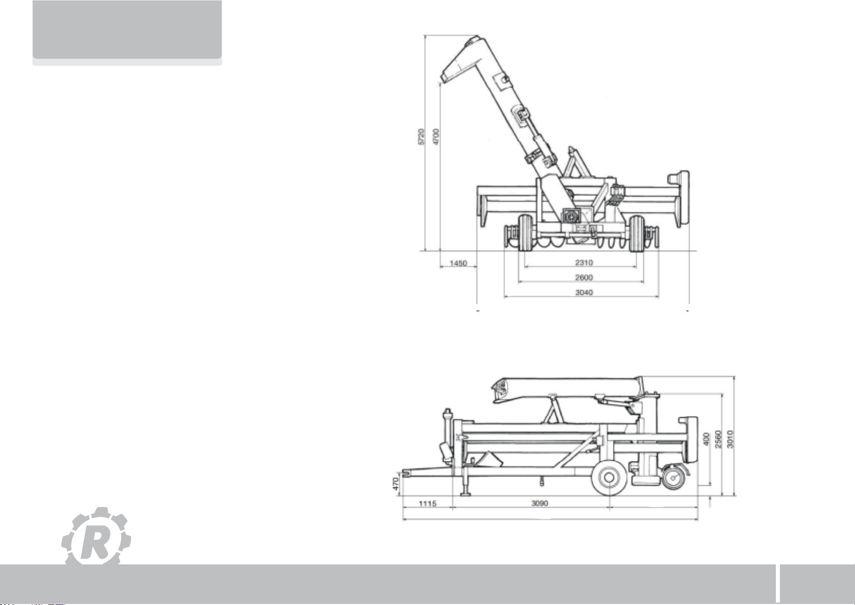
Unit: Hydraulic-Mechanical Grain Bag Unloader
Model: EA-910
RICHIGER MAQUINARIAS S.A, located in Avellaneda 661, Sunchales, Santa Fe province, Argentina, warrants its
product EA-910 mechanical grain unloader from defects in materials and workmanship under normal operating
conditions and proper application, in accordance with the specifications for operation as described by the
manufacturer, for the period of 365 days from date of delivery to buyer.

Limitations on Warranty
Within 15 days after delivery to or receipt by the buyer of the product, the buyer shall inform the seller in writing if
product is found defective or short in any respect. Failure to so inform the seller or any use by buyer of product shall
constitute conclusive evidence that the seller satisfactorily performed and the buyer waives any right to reject the
product thereafter
The first buyer is responsible for proof of delivery date of product for the purpose of establishing warranty time of
validity. Warranty can continue for new user should the product be resold by the first buyer during valid period of
warranty, only if this situation is reported in writing, with enclosed documentation as proof of purchase. Warranty will
not be applicable if series number or other identification markers are erased, obliterated or otherwise altered.
The following are types of failures which are not attributable to defects in materials and/or workmanship and which
are not considered by RICHIGER MAQUINARIAS S.A as part of the warranty extended hereunder. This listing is by .
way of example and is not intended to be exhaustive:
1) Product suffered damages attributable to accident, abuse, neglect or ignorance.
2) Product was not used in accordance with manufacturer's recommendations.
3) Product did not receive required maintenance.
4) Failure ensued after replacement of original parts without express consent of RICHIGER
MAQUINARIAS S.A , or modifications that in RICHIGER MAQUINARIAS S.A.’s judgment may have .
affected performance, safety and/or dependability parameters.
5) Product was used in a manner or for a purpose for which it was not designed or intended to be used.
6) Incorrect mounting of external gears, pulleys.
7) Stripped splines or keyways on drive shafts.
8) Damage due to deterioration during periods of storage by the purchaser prior to operation.
9) Damage of any kind from erosive or corrosive action of any gases or liquids handled by the machinery.
10) Lack of or incorrect type of hydraulic fluid, lubricant, oil and/or grease.
11) Contamination of hydraulic fluid.
12) Operating beyond recommended maximum speeds, pressures and temperatures.
13) Repairs or disassembly by unauthorized personnel.
14) Misalignment of drive shafts, gears, sprockets and power driven elements.
15) Damage due to voltage spikes, static discharge, electrical storms, physical abuse, externally controlled
device failure and improper fusing.
Buyer inspection and acceptance

Cut-Out Warranty Registration Card
This form must be filled out and signed by the customer at the time of delivery, and sent
to factory within 30 days of delivery.
Machine Description:
Model #:
Unit #:
Date of Purchase: Date of Delivery:
Customer Name:
Address:
City: State:
Dealer Name:
Address:
City: State:
The machine detailed above and the Operator's Manual have been received and I understand and have been thoroughly instructed
by my dealer about how to operate the machine, Operator's Manual content, equipment care, safe operation & warranty terms, and
have personally reviewed the Warranty Policy Terms.
Buyer's signature:

Richiger Maquinarias SA
Avellaneda 661,
S2322BCM Sunchales,
Province of Santa Fe,
Argentina
Cut-Out Warranty Registration Card
This form must be filled out and signed by the customer at the time of delivery, and sent
to factory within 30 days of delivery.

17. page 27
General indications for efficient operation
20. page 35
Parts list
15. page 25
Lubrication schedule
19. page 32
Hand signals
18. page 31
General indications and safety tips
16. page 26
The grain flow concept
14. page 23
Lubrication chart
02. page 03
Dimensions
03. page 04
Safety precautions
04. page 05
A word about the hydraulic controls.
05. page 06
Switching from transport to work
06. page 09
Attaching the bag
07. page 13
Grain extraction procedure
08. page 16
Ending grain extraction
09. page 16
Emptying the last section of bag
10. page 19
Detaching bag from roller
page 20
11.Back to transport position
page 21
12.Maintenance
13. page 22
Gear oil filling procedure
page 02
01. Technical specifications
Index
9
01

01
Technical specifications Materials to be extracted All kinds of dry grains (wheat, sorghum, maize, sunflower, soybeans, rice,
etc.) and pelletized materials
Capacity Up to 300 tons/tour (*)
Minimum power: 60 CV
Tractor
PTO revolutions: 540 rpm
Extraction High clearance discharge auger, mechanical drive
Drive shaft w / shear bolt protection
PowerTransmission
Mechanical central discharge auger & cross augers
Tires 11 L15 – 10 ply
Extraction system Automatic bag pickup system
Working height hydraulically controlled
Bag slasher blade
Works mechanically and hydraulically
Adjustable working width
Tire pressure: 30 lbs./sq. in.
Total weight 2000 kg. (4400 lbs.)
(*) Work capacity can vary according to grain type, moisture content and other factors
Manufacturer reserves right to change specifications at any given time without previous notification
02

02
Dimensions in millimeters
Work position
Transport position
9
03
5200
2500
6705

IMPORTANT
The operator should become familiarized with machine controls before attempting actual operation. Keep unit in
good working condition. Any modification could cause malfunctioning, potentially dangerous situations, or reduced
machine durability.
03
In order to obtain maximum performance from your grain bag unloader, we recommend you keep
the owner's manual in a handy place for quick consultation. Read the manual carefully before
attempting to unload grain from bags and pay special attention to operating and maintenance
instructions.
Safety precautions
For the operator
Before transporting the grain unloader, verify that:
a) The tow bar pin is properly secured
b) Check tire pressure
c) Check that wheel bolts are properly tightened
d) Attach safety chains between machine's tow bar and
tractor drawbar for added security on the road
Most accidents are caused by human error. Follow all safety procedures.
Make sure all people are safely positioned before starting tractor's engine and engaging
the PTO.
Keep unloader clean and sheltered when not in use. This diminishes risk of deterioration
and eventual failure.
Keep a fire extinguisher handy.
Decals with safety indications and warnings should be strictly heeded, kept in good
condition and replaced if necessary.
When towing the machine, drive with the utmost caution on public roads.
Keep hands, feet and clothing well away from moving parts.
Stop the tractor's engine before attempting a hands-on task on the unloader.
04

As will be seen in this manual, there are frequent references to the first lever, the second lever, and the third lever of the valve that regulates hydraulic
flow rates, and thus operating speeds. In the diagram below can be seen the first and second levers (which open and close the hydraulic cylinders)
mounted on valve sections to the left of the control knob, and the third lever (which drives the roller) mounted on a valve section to the right of the
control knob.
The diagram shows the speed effect that turning the knob clockwise or anticlockwise, in combination with each specific lever, will have on the different
hydraulic circuits.
For example, setting roller speed on initiating extraction is simpler if starting from low revs and then increasing them as necessary. In this case the
knob can initially be turned completely clockwise, in which position the roller will not move at all, and then progressively be turned counterclockwise
until the desired rpm are attained. In another example, if one of the cylinders does not move when the corresponding lever is operated, it would
indicate that the knob is turned completely anticlockwise and no oil is flowing through that circuit. It will be therefore necessary to turn it clockwise.
04
A word about the hydraulic controls.
9
05

05 WARNING:
At no time during the unloading operation should anyone, except the operator standing at the
hydraulic controls, approach unloader or bag, and that includes both tractor and truck drivers.
Onlookers should keep a safe distance. And never allow anyone to lean against the bag: augers are
turning inside.
2) To the side of the machine, on the roller
cross beam, an array of three levers, a turn knob
and a pressure limiting valve control the
unloader's hydraulics. A decal attached next to
them (Fig. 1) shows each control's function.
First step in preparing for work is raising the
discharge auger. With the tractor's hydraulics
turned on, move first lever “A” its upward position
(Fig. 2). This will raise the auger tube.
As soon as auger is fully extended, move back
the lever to its mid (neutral) position. Once the
unloader has finished working and is to be towed
away, the sequence is reversed and the tube is
lowered by moving down the lever.
The sequence ends once the upper half is resting
firmly upon its transport prop and the control lever
is returned to neutral position.
1) Hitch tractor to unloader, connect hoses to
the tractor's hydraulic circuit and connect drive
shaft to the tractor's power take-off.
Fig.1
Fig.2
Switching from transport to work
06

NOTE:
A pressure limiting valve set to 850 PSI is provided as a safeguard against excessive pressure in the hydraulic circuit.
If this value is exceeded, oil will bypass the hydraulic motor and momentarily bring operation to a standstill.
Fig.3
Fig.4
3) Next, the second lever is used to regulate working
height (i.e., clearance of the sweep augers to the ground)
by means of a hydraulic cylinder. First, this center lever
should be moved to top position in order to raise the
unloader. To adjust for desired clearance, and the object
here is to set the sweep augers as close to the ground as
possible without scraping against it and compromising
bag integrity (see “General indications for efficient
operation” on page 26), a set of three clamp-on stops of
different size is provided.
Once a combination of stops or a single stop have
been selected and placed around the cylinder rod,
second lever “B” is pulled down (Fig. 3) so that the
weight of the unloader comes to rest upon the stops (Fig.
4). At this point the lever is returned to its neutral position.
The height of the machine can be modified at any point,
even when the sweep augers are inside the bag.
IMPORTANT:
The unloader should not be raised or lowered with the hydraulic cylinder if the augers are deep within the grain mass,
as this could place undue strain on some components. The correct procedure is to release a few feet of plastic from
the roller by counter rotating it hydraulically, advance forward with tractor to extricate the sweep augers from the
grain, modify machine clearance with the hydraulic cylinder removing or adding stops as necessary, back the machine
once again into the bag to position the augers next to the grain, and reinitiate PTO and roller to continue unloading.
9
07

7) Lower the support stand and reinsert pin
at the base (Fig. 8).
5) Remove the pin at the base of the support stand,
swing the stand upward and attach temporarily to main
beam with same pin (Fig. 5).
4) The third lever, used to control roller rotation,is
not used at this stage.
6) Pull back the
spring-loaded pin that holds the
roller assembly in place during
transport and swivel it 90º to
work position (Figs. 6 & 7).
Fig.5
Fig.7
Fig.8
Fig.6
08

06 Attaching the bag
1) Open the end of the bag
and along the top section make
a lengthwise cut approximately
2 meters (7 ft.) long.
Spread open the resultant flaps
to the side
(Figs. 11 & 12).
8) Remove the sweeper
screw extensions from their
transport location and insert
them in the main auger shafts,
not mixing left and right hand
screws. Also remove protection
grids and install (Figs. 9 & 10).
9) The sequence is
reversed when changing back
to transport mode. Fig.10
Fig.12
Fig.9
Fig.11
CAUTION:
Do not prolong the cut to the point where grain is filling the bag and exerting pressure. This could cause a rip that
spreads along the full length of the bag.
9
09

4) Pull the third lever “C” up
to rotate bag pick-up roller
forward until the sharpened
studs that hold the bag reach
topmost position (Figs. 15 & 16).
If roller does not turn initially,
hold lever up for a few more
seconds until clutch engages
automatically. Then move lever
back to neutral.
2) Turn the cutter blade
around so that its cutting edge
faces outward. The blade will
cut open the bag as the roller
pulls it in.
(Fig. 13).
3) Drive the tractor/unloader pair in reverse
and align with the bag opening as straight and dead
center as possible.
Back up the unloader into the bag until the sweep
augers come lightly in contact with the grain, but do
not shove or attempt to wedge the sweep
augers forcefully into the mass of grain.
Be careful that the wheels are not treading on any
part of the bag (Fig. 14).
Fig.13
Fig.14
Fig.16Fig.15
10

5) Lift the bottom half of the bag bringing it up to
the roller. Notice that the bottom half is one
continuous section of plastic that runs the entire
length of the roller and that it is the black inner layer
of plastic that is visible.
Punch the plastic sheet through each holding stud
(Fig. 17) leaving a remainder of 10 or 20 inches to the
edge.
Do not worry if the plastic is not perfectly distributed
along the length of the roller or if folds and creases
remain after attachment (Fig. 18).
Fig.17
Fig.18
9
11

6) Once the bottom half of the bag has been
secured in this manner, place the upper half over the
bottom half already fitted; punch the plastic sheet
through each stud (Fig. 19), starting from the studs at
the end of the roller and progressing toward the
center. Notice that it is the white outer layer that is
now visible and that there are two sections of plastic:
the initial cut has divided the top part of the bag in two
parts. The left segment must be passed to the left of
the discharge auger and fastened to the studs on that
side of the roller, while the right segment must be
passed to the right of the auger tube and fastened to
the studs on that side (Fig. 20). Once unloading
operation is underway, the initial cut will be continued
by the cutter blade.
Once unloading operation is underway, the initial cut
will be continued by the cutter blade.
Fig.19
Fig.20
IMPORTANT:
There is no need to be overly precise when fastening the bag to the roller. Even though at this stage the plastic may
look crumpled and in disarray, it will stretch and straighten after a few turns of the roller. The basic consideration here
is having the bottom part of the bag (the part hooked to the roller first) hold some slack relative to the upper part
attached last (one or two feet is enough). The latter should be attached shorter so that the roller tugs at it first. The
small margin of slack in the bottom section plus the plastic sheet's elasticity helps form a rounded shape that contains
the grain as the bag is rolled in. The round shape also helps keep adequate clearance between bag and sweep augers
(see “General indications for efficient operation”, page 27).
12

2) Engage the tractor PTO with engine idling, throttle so PTO reaches 500/540 rpm's and once the augers are
turning move the roller control lever to its upper position. Normally it is left in that position until the unloading
operation is finished (Fig. 23). Turn to the variable flow valve. This valve handles roller rotation speed through a
turning knob located at the top of the hydraulic valve array (Fig. 24). Turning the knob anti-clockwise increases
rotational speed; turning it clockwise decreases it. The higher the speed, the more grain is brought in. At any point
during operation roller can be brought to a complete halt by closing the valve knob. Open the valve if it was
previously closed and augment speed so that grain begins to be delivered through the discharge auger and to
accumulate at the front end of the bag.
1) Make absolutely sure that the tractor's gear case is disengaged and brakes are off. Failure to
comply with this can result in a torn bag or mechanical malfunction. The machine is now ready to begin
unloading grain. First, pull up third lever “C” (Fig. 23) to turn roller forward about half a turn or more so
that it gatherssome plastic sheet (Fig. 21) and then move lever back to neutral. Check that the bag
passes through the cutter blade located on the auger tube (Fig. 22) in preparation for beginning work.
07
Grain extraction procedure
Fig.22
Fig.24
Fig.21
Fig.23
9
13
Table of contents
Other Richiger Farm Equipment manuals
Popular Farm Equipment manuals by other brands

Vicon
Vicon Andex 694 EVO Assembly instructions

AIMA
AIMA TWIST STANDARD Use and maintenance manual

AGCO
AGCO New Leader L4258G4 Workshop service manual

Victory
Victory Super 7 Operators manual and parts lists

Hanskamp
Hanskamp SpiderServer Installation and operating instructions

Headsight
Headsight CORN DRAGO 09020801j installation manual