Richmond FUJI FA-200 Installation and operating instructions

FUJI FA-200
AERO SUBARU
SEMI SCALE SPORT MODEL
Assembly
and
Operations Manual
Please review this manual throughly
Before assembling or Operating
The
AERO SUBARU
Semi scale sport model
AERO SUBARU
We’ve used our ULTRA TOUGH POLYCOTE ECS Enhanced Covering System
for this Model
TM

Stage 1 – WING ASSEMBLY.
JOINING THE WING HALVES
2
1. Locate the wing joiner (also called Dihedral brace). Using the ruler, determine the center of the wing joiner and
mark it with a pencil
1.1 Orientation of wing joiner and dowel
guide 1.2 Trial fit the wing joiner and dowel guides
wing joiner
dowel guides
4. Apply plenty of 30 minute epoxy to one end of the wing joiner, using a stir stick or epoxy brush. Carefully insert
the joiner into the first wing panel as shown in the sequence below, then wipe off the excess glue that squeezes
out of the joint with a cloth or tissue. Repeat this process several times to ensure that the wing joiner and cavity
are well coated in epoxy.
Do not use 5 minute epoxy to join the wings
1.3 Apply CA glue to secure dowels into their places 1.4 Apply plenty of epoxy glue to the wing
joiner.
2. Trial fit the wing joiner into the wing panels. It should insert smoothly up to the center line marked in 1.1. Now
slide the other wing panel onto the wing joiner until the wing panel meet. If the fit is overly tight, it may be neces-
sary to sand the wing joiner.
- Right/left wing panels - Rolled trim strip (supplied with kit)
- Wing joiner (also called dihedral brace) - 30 minute epoxy
- Two short dowel guides - Epoxy brush or stir sticks
- Disposable mixing dish for the epoxy
- Sandpaper (Coarse 240 grit recommended)
- Low tack masking tape
- Pencil
- Knife
- Ruler
- Paper towels.
Parts needed Tools and Adhesives needed
3. Insert the dowel guides into one of the wing panels all the way to the center lines. Apply CA glue to secure the
dowels into their places.

Stage 2
Stage 3
3
When the glue has cured in Stage 1, trial fit the second wing panel
onto the first to ensure that the two panels fit without an excessive
gap.
Now apply plenty of epoxy to the joiner and wing rib where it will
join the second wing panel of epoxy. Use 30 minutes epoxy to
ensure a strong bond and give yourself plenty of working time. As
with the wing joiner, the epoxy should ooze from joint and the
excess cleaned off with a rag or tissue before it cures.
Use low tack masking tape to hold the two panels together until the
glue cures.
1.5 Carefully insert the joiner all the
way to the center line
2.1 Apply plenty of 30 minute epoxy
glue
2.3 Slowly close the gap
2.4 Use tape to hold tightly together
Once the glue has cured completely (allow several hours at least), the tape can be removed from the wing panels.
To cover the joint in the wings, a length of wing joiner tape is supplied. Starting from the upper side, stick the tape
centrally over the joint ensuring that it is pressed down firmly as you work around the wing. Wrap the tape all the
way around the wing joint in one piece, starting and finishing at the wiring harness cavities at the bottom of the
wing.
Center line
1.6 Wipe off the excess epoxy
2.2 Align the two wing panels
3.3 Trim off the excess here
3.2 Carry on over the bottom of
wing press down firmly as you go
3.1 Applying tape over the joint,
starting here

Stage 4
Stage 5
4
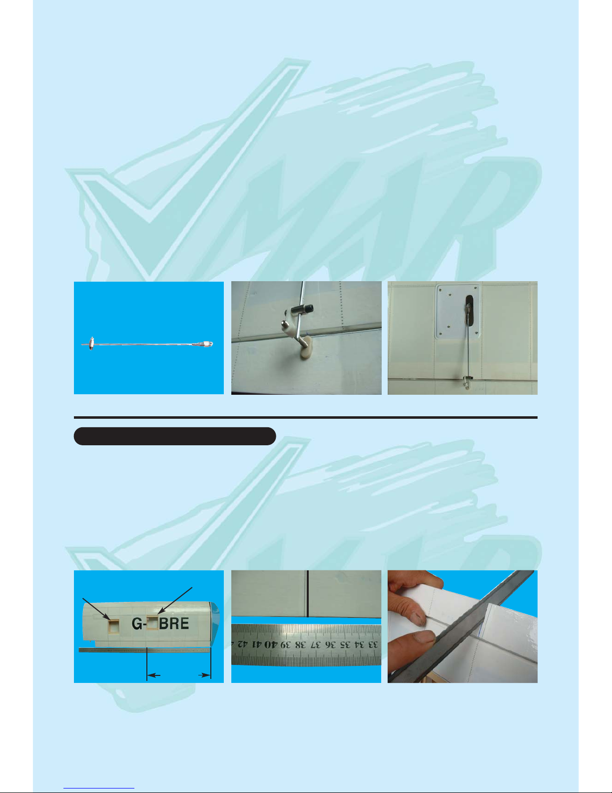
Carefully remove the white cover plates from the aileron
servo cavities. Ensure you know which cover plate is for the
right wing and which is for the left. Remove the white cover
plates and retain the mounting screws. Notice that there are
wooden servo rails pre-installed into each servo cavity end.
Locate the wiring harness tubes that are protruding slightly
into each aileron servo cavity. The tube can be moved slight-
ly at this point. Check out the other end of each tube for a
clean position and then using C/A glue secure the wiring har-
ness tubes at the aileron servo cavity end.
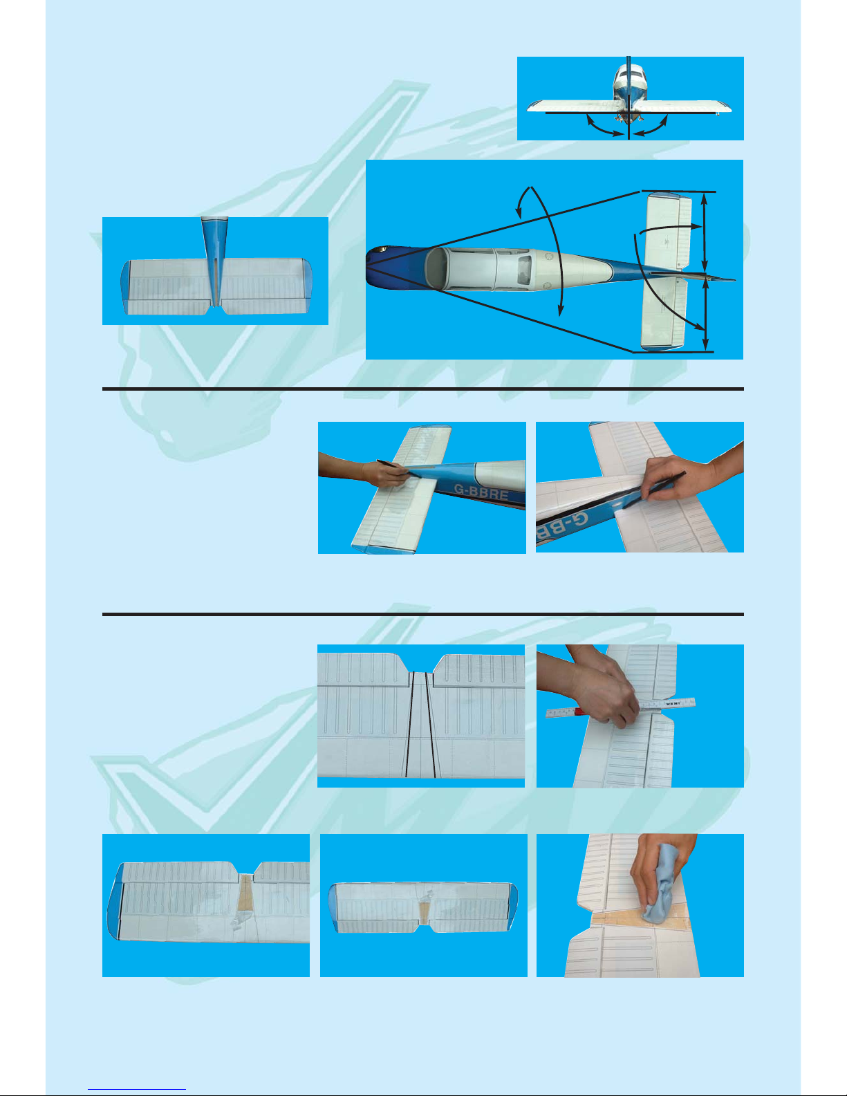
Install a servo in each aileron servo cavity and connect the
servo wire to the servo extension wires and run the extension
wires through wiring harness tubes to the centre of the wing
Install the aileron control horns
Aileron servos cavity
4.2 Aileron servos location
4.3 Aileron servos mount 4.4 Screw servo in position 4.5 Install aileron control horn
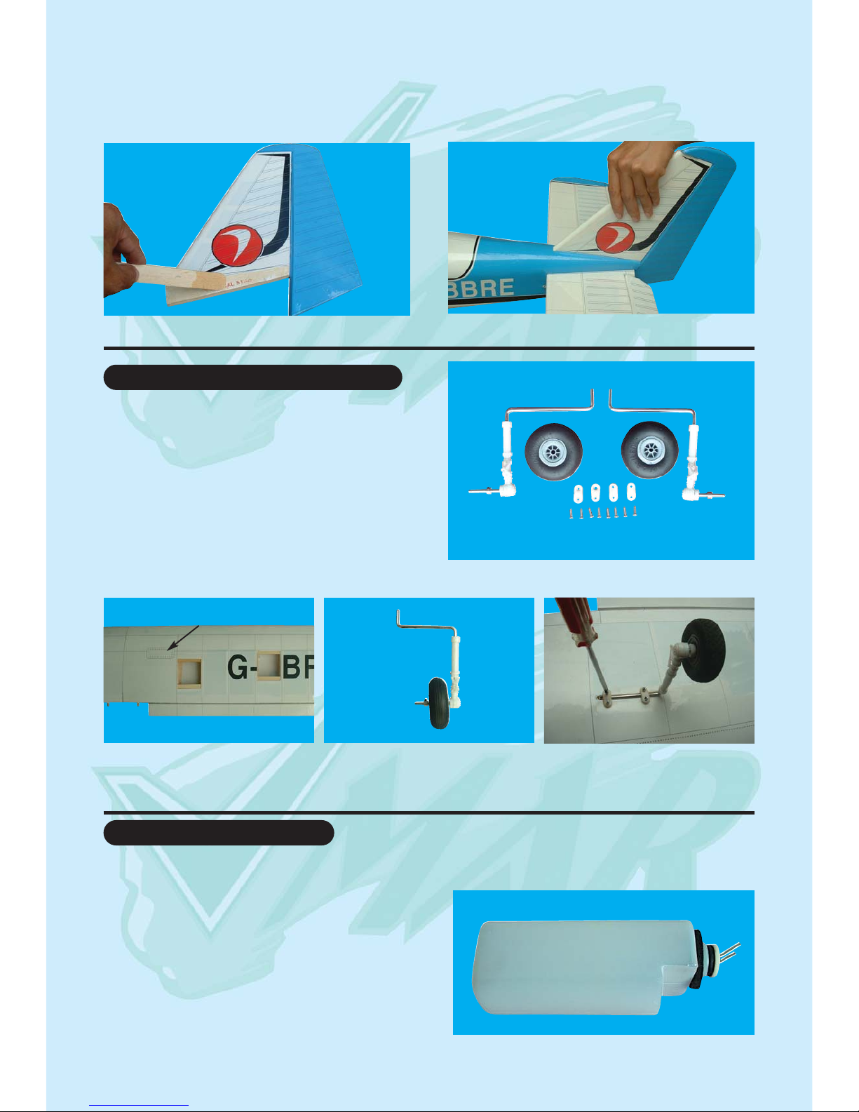
Step 1 Consult your radio instruction manual and center each aileron servos by plugging it into the aileron channel
in the receiver. Turn on the transmitter and then the receiver. Center the aileron trim lever on the transmitter.
Remove the servo arm mounting screw and the servo arm.
Step 2 Mount the servo arm back on the servo. Position the arm to be parallel with the back edge of the wing. Screw
the arm into place with the servo arm mounting screw supplied with the servo.
Locate the two aileron control rods in the hardware bag. Ensure the clevises are screwed well onto the threaded
portion of the rod. Rotate and tug aggressively on the clevises and ensure that they are not loose on the rods.
Tape the ailerons into their neutral position so that they are even with the trailing edge of the wing and not pointing
either up or down.
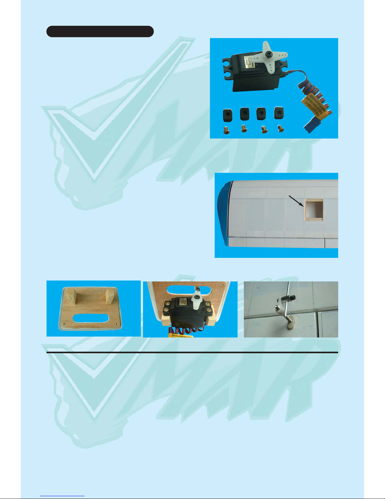
To install the aileron servos into the wing you will need the
following items :
- 2 servos
- Servos mounting screws and grommets as supplied with
servos.
- Servo control arms as supplied with the servos.
- Two aileron control rod assemblies supplied with the kit.
The assemblies consist of a metal rod with a clevis screwed
onto one end.
- Low tack masking tape.
- 2 aileron control horn assemblies
- 1 servo Y connection wire
FITTING AILERON SERVOS
4.1 Prepare the servos by fitting the rubber
grommets & ferrules supplied with your radio

Stage 6
5
5.1 Aileron control rod assembly 5.2 Aileron control horn assembly 5.3 Aileron control installed
FITTING FLAP SERVOS (Option)
To install the flap control system, you will need the following items :
- 2 servos
- Servo mounting screws and grommets as supplied with the servo.
- Servo control arm as supplied with the servo.
- Two flap control rod assemblies
- Low tack masking tape.
- Ruler
- Hacksaw blade.
Flap servo cavity
Step 3 Ensure that the aileron control horns are screwed onto the threaded aileron control horn bolts and that both
control horns are in approximately the same place on their respective bolts.
Step 4 Connect the aileron servo rods to the aileron control horns.The one end with clevis will be attached to the
servo output arm.
Step 5 Connect the other end of the rod to the control horn pre-installed with an EZ connector
Step 6 Remove the masking tape holding the ailerons.
Step 7 In the case of computer radios the servos together by connecting them to the appropriate receiver channel.
In the case of analog radios couple the servos together using a Y harness
Step 8 Turn on your radio and activate the ailerons, using the aileron stick and ensure a smooth full motion can be
achieved.
Step 9 With the wing top side up and viewed from the back, ensure that moving the transmitter aileron stick to the
left raises the left aileron and lowers the right aileron. Movement of the stick to the left will roll the aircraft to the left.
(Counterclockwise roll of the wing when viewed from the back ).
Step 10 With the wing top side up and viewed from the back, ensure that moving the transmitter aileron stick to the
right raises the right aileron and lowers the left aileron. Movement of the stick to the right will roll the aircraft to the
right.
Aileron servo cavity
The AERO SUBARU comes with full span aileron. ONLY
follow this stage when you decide to fly this airplane with
flaps.
6.1 Define the separated line
between flap and aileron with a
ruler.
375 mm
6.2 Mark the separated line at
375mm from the wing-tip. using a
water solublenon-permanent felt-
tip pen
AILERON
6.3 Carefully cut completely thru
the aileron follow the marked line
with a hacksaw blade.

6
6.4 Install servo to the servo
mount
6.5 Install the control horn to the
flap
6.6 Final flap installation
6.7 Flap up position 6.8 Flap down position
FITTING THE HORIZONTAL AND VER-
TICAL STABILIZERS
To install the stabilizers to the fuselage you will need:
- Fuselage
- Vertical stabilizer with pre-installed rudder
- Horizontal stabilizer with pre-installed elevator
7.1 The completed fuselage slot should look like this
Vertical slot
Horizontal slot
7.2 Horizontal stabilizers with pre-installed elevator 7.3 Vertical stabilizers with pre-installed rudder
Stage 7

Stage 8
Stage 9
Stage 10
7
Check the fit of the horizontal stabilizer
in its slot. Make sure the tail is square
and centred to the fuselage by taking
measurements as shown in the dia-
grams on the right, but don not glue any-
thing yet.
Equal
distance
Equal distance
900
8.1 Trial fit the horizontal stabilizer in
its slot
With the horizontal stabilizer cor-
rectly aligned, mark the shape of the
fuselage on the top and bottom of
the tailplane using a water sol-
ublenon-permanent felt-tip pen as
shown here.
9.1 Mark the top of the horizontal
stabilizer ...
9.2 ... and the bottom
Now remove the horizontal stabiliz-
er, using a sharp knife and a ruler
CAREFULLY cut 2mm inside the
marked lines and remove the cover-
ing on the top and bottom of the tail
as shown. Make sure you only cut
the film and not the wood, otherwise
the horizontal stabilizer will be
severely weakened.
10.1 Mark lines on horizontal stab 10.2 Cut inside the lines
10.3 Remove covering from top
surface
10.4 Exactly the same underneath 10.5 Clean off any traces of pen

Stage 11
Stage 12
Stage 13
8
Now apply sufficient epoxy to the top and bottom of the
horizontal stabilizer. Use 30 minute epoxy to ensure a
strong bond and give yourself plenty of working time.
Insert the horizontal stabilizer in its slot in the fuselage
and re-check the alignment. Excess epoxy should be
cleaned off with a rag or tissue before it cures.
11.1 Apply plenty of epoxy 11.2 Slide the horizontal stabilizer
in place
11.3 Wipe off excess epoxy
Check the fit of the vertical stabilizer in its slot.
Make sure that it is glued square to the horizontal
stabilizer and fuselage
FITTING THE VERTICAL STABILIZER WITH RUDDER
12.1 Trial fit the vertical stabilizer onto fuselage.
13.1 Mark both sides of the verti-
cal stabilizer
13.2 Carefully cut through the
covering
13.3 Remove covering from both
sides
Mark the shape of the fuselage on the left and right
sides of the vertical stabilizer using a felt-tip pen. Now
remove the vertical stabilizer, using a sharp knife &
ruler, CAREFULLY cut just 2mm inside the marked
lines and remove the covering on both sides of the fin,
just as you did with the horizontal stabilizer, making
sure you only press hard enough to cut the covering,
not the vertical stabilizer.

Stage 14
Stage 15
Stage 16
9
Now apply sufficient epoxy to both sides and the bottom
of the vertical stabilizer. Use 30 minute epoxy to ensure
a strong bond and give yourself plenty of working time.
Insert the vertical stabilizer in its slot in the fuselage
and re-check the alignment. Excess adhesive should
be cleaned off with a rag or tissue before it cures.
14.1 Apply plenty of epoxy 14.2 Slide the fin in place
FITTING THE MAIN LANDING GEAR
Identify the main landing gear components shown below
- 2 main landing gear esemblies
- 2 main wheels ( 60mm x 20mm)
- 8 sheet metal screws with 4 traps
- 2 collars
15.1 Main landing gear components
15.2 Turn over the wing to locate
the pre-drilled main landing gear
mounting holes.
15.3 Main landing gear assembly 15.4 Use 4 sheet metal screws
and 2 traps to mount the main
landing gear onto the wing
Pre-drilled main-landing
gear mounting holes
FITTING THE FUEL TANK
To assemble the fuel tank you will need the following items:
- The fuel tank and fuel stopper assembly (supplied)
- The clunk (supplied)
- About 7” (20 cm) of medium ID silicone fuel line (DUB 197
or similar)
- Cross head Phillips screw driver

Stage 17
Stage 18
10
16.2 Use 100 mm (4 in) for fuel line
and 50 mm (2 in) for pressure line
16.3 Illustration of fuel line posi-
tioning inside the tank
16.4 Fuel tank installed on the
power module
100 mm (4 in) for fuel line
50 mm (2 in) for pressure line
fuel line
pressure line
INSTALLING THE ENGINE
The engine and the fuel tank are installed onto the
power module. First remove the power module from
the fuselage by removing the 4 nuts & washers
17.4 Pitts type muffler is suitable
for VMAX .46 and VMAX .52
17.5 Install the muffler to the
engine and connect fuel lines
17.1 Power module with pre-installed engine
mount and nose gear bearing
17.2 VMAX .46 or VMAX .52 2 stroke-engine are
recommended
17.3 Fit the engine to the pre-
installed engine mount
Connect to the fuel line
Connect to the pressure line Fuel line
Pressure line
INSTALLING THE NOSE GEAR
18.1 Nose gear components
Identify the main landing gear components shown on the
photo 18.1:
- 1 nose gear with strut
- 1 steering arm
- 1 wheel collar
- 1 wheel
110 mm

Stage 19
Stage 20
11
19.1 Power module installed to
the fuselage
19.2 SUBARU cowl pre-cut and
decorated, suitable for VMAX .46
and VMAX.52
19.3 Install suitable Propeller and
spinner after finishing the cowl
installation.
18.2 Place the steering arm with pre-install EZ
connector to the nylon nose gear bearing
18.4 Insert the nose gear push rod to the EZ con-
nector
18.3 Slide the nose gear to the bearing, passing
through the steering arm. Secure the steering arm
to the nose gear by tighting the hex-nut to the
mark on the nose gear.
18.5 Typical nosegear installation
To the rudder servo
INSTALLING THE COWL
FITTING ELEVATOR AND RUDDER CONTROL HORN
The elevator control is fitted on the underside of both right and left
of the elevator halves. Pierce the covering over the pre-drilled hole
for the control horns installation as shown. 20.1 Control horn

Stage 21
Stage 22
12
20.2 Elevator control horn location 20.3 Rudder control horns loca-
tion
20.4 Elevator and rudder control
horn connected to the control rod
Elevator control horn location
INSTALLING THE SERVOS
Install the rubber servo grommets and brass ferrules supplied with your radio
equipment. The three servos that control the elevator, rudder and throttle are
Installed in the servo tray mounted in the fuselage. Remove servo tray from
the fuselage, mounting the servos to the servo tray as shown. 21.1 Universal servo mount
21.2 Note the orientation and positions of the
three servos in their tray
Throttle servo Elevator servo
Rudder servo
21.3 Throttle, elevator and rudder servos connect-
ed to their push rod
22.1 Consult the picture showing how the throt-
tle, rudder and elevator servos are positioned
and connected to the pushrods.
CONNECTING THE PUSHRODS TO THE THROTTLE, RUDDER AND ELEVATOR SERVOS

Stage 23
Stage 24
Stage 25
13
Connect the elevator servo to the receiver and turn on your transmitter. Confirm that the
neutral positions of the elevator servo are sustained as per illustration 22.3
22.2 Pre-installed elevator, throttle
and rudder pushrod
22.3 Connect clevises on pushrods to the servo arms first, then
install the servo arms to the servos
CONNECTING THE PUSHRODS TO THE ELEVATOR
23.1 Two independent elevator
control horns shown in position
23.2
Loose the collars
to connect the elevator pushrods to the elevator
control horns,
align the elevator surfaces, then tighten collars
securely.
CONNECTING THE PUSHRODS TO THE RUDDER
Connect the rudder servo to the receiv-
er and turn on your transmitter. Confirm
that the neutral positions of the rudder
servo are sustained as per illustration
22.3
24.1 The rudder pushrod is connected to the rudder control
horn
CONNECTING THE THROTTLE CONTROL
Connect the clevis to the engine throttle arm at roughly half throttle. Look
into the throat of the engine carburetor as you rotate the throttle arm and
select a position where the throttle opening is about haft what it is when
fully open.
25.1 Throttle control rod
Connected to the engine throttle arm
engine throttle arm
25.2 Throttle control rod connect-
ed to the engine throttle arm
Elevator pushrod
Throttle pushrod
Nose gear pushrod
Rudder pushrod

Stage 26
Stage 27
14
Adjust the deflection of the control surfaces to match the specifications on page 15
You can reduce the amount of throw by doing either or both of the following:
- From the servo end, move the clevis or EZ connector to a hole in the servo arm that is closer to the servo output
shaft.
- From the control horn end, move the horn out further on the threaded bolts. Always confirm that the horn is still
thoroughly engaged with the threaded bolt after you have adjusted it.
ADJUST CONTROL SURFACE THROW LIMITS.
FINAL R/C SET-UP
Before starting the final
set-up of the model,
switch on the radio and
ensure that all trims are
in their neutral posi-
tions. Check that the
ailerons, elevator and
rudder are centred. If
any adjustments are
needed, do these by
uncoupling the relevant
clevis and turning it
clockwise to shorten
the linkage or counter -
clockwise to lengthen it.
Only when each control
surface has been cen-
tred mechanically in
this way should you
begin adjusting the sur-
face movement (or
throw)
Now confirm
that the con-
trol surfaces
are moving
in the correct
direction.
Use the
servo revers-
ing switches
on your
transmitter to
reverse the
direction of a
servo if nec-
essary. The
most popular
transmitter
mode (with
the throttle
on the left,
with ailerons
and elevator
on the right)
is shown
here.
Stage 28
ELEVATOR
UP
ELEVATOR
DOWN
AILERON
UP
AILERON
DOWN
AILERON
DOWN
AILERON
UP
RUDDER
RIGHT
RUDDER
LEFT

29.1 Consult your radio manual for instructions
about hooking up your receiver battery, receiver and switch harness.
29.2 Wrap the battery pack securely in foam suitable for RC equipment and wrap the foam insulated pack in a plas-
tic bag or cling wrap.
29.3 Thread the battery pack connector back through from beneath the fuel tank to the radio compartment by pass-
ing the battery connector through an opening beside the fuel tank.
29.4 Connect the battery connector to your radio system according to the radio manual.
30.1 Consult your radio manual for instructions about hooking up your receiver.
30.2 Plan where you are going to put the receiver with consideration for routing the antenna safely.
30.3 Wrap the receiver securely in foam suitable for RC equipment and wrap the foam insulated receiver in a plas-
tic bag or cling wrap.
30.4 Generally in the absence of specific instructions from the radio manufacturer, it is recommended that the
receiver should be placed where it is least likely to have impact during a crash. Keep the battery pack and other
heavy loose items ahead of the receiver.
31.1 Consult your radio manual for instructions about testing and operating your radio system.
31.2 Pay particular attention to charging your radio system batteries and range testing the system before and after
each flight.
31.3 Check that all controls are working correctly before and after each flight.
The CG for your AERO SUBARU is located at 80 to 85 mm (3 1/8“ to 3 3/8 inch ) back from the leading edge of
the wing when the wing has been attached to the fuselage.
For the initial flight, the CG should be located at 3 1/8” (80mm) back from the leading edge of the wing when
the wing has been attached to the fuselage.
The CG is measured with the engine, radio gear and all other components installed but WITH NO FUEL IN THE
TANK.
Set up the CG as it will be when you fly it BUT WITH NO FUEL IN THE TANK.
It is very important to have the CG correct. Flying your model with the CG too far will likely lead to loss control and
a crash.
If you discover that after you have assembled your model and installed your radio and engine that the CG is incor-
rect you must bring the CG to the correct location by doing the following BEFORE FLYING :
- Move the battery pack fore or aft.
- Move other components fore or aft.
- Change engine to a lighter or heavier model.
- Add weight to the nose or tail. If adding it to the nose, try to make it useful by going to a heavier duty engine
or adding a spinner with a heavy metal backing plate. As a last resort, add stick on “dead” weight where appro-
priate.
15
INSTALLING THE RECEIVER BATTERY
Stage 29
Stage 30 INSTALLING THE RECEIVER
Stage 31 CONFIRM RADIO OPERATION
Stage 32 BALANCING THE AIRCRAFT.

16
NOTE : The throws are measured at the widest part of the elevator, rudder and aileron. Adjust the position of the
pushrods at the control/servo horns to control the amount of throw. You may also use the ATV’s if your transmitter
has them but the mechanical linkages should still be set so that the ATV’s are near 100% for best servo resolution.
High rate Low rate
ELEVATOR 1/2 “ ( 12mm) up 1/3” (7mm) up
1/2 “ ( 12mm) down 1/3” (7mm) down
RUDDER 1 “ (25mm) right 5/8” (13mm) right
1” (25mm) left 5/8” (13mm) left
AILERON 3/8” (11mm) up 1/4” (8mm) up
3/8” (11mm) down 1/4” (8mm) down.
Note: If your radio does not have dual rates, then set the control surfaces to move al the low rate throws.
33.1 Once you have confirmed that the CG is
correct, you should do a thorough review of the
entire model before your first flight. Check every-
thing twice! Every hook up, every coupling, every-
thing! Do it twice!!
33.2 Before your first flight , have an experienced
flyer review your work. Do not fly your model until
it has been checked out by a third party who
knows how to fly and how to set up a model air-
craft
33.3 Once you have completed your first flight,
get in the habit of checking your model over
before and after each flight! Don’t fly if you find
something that is not right!
Stage 33 CONFIRM MECHANICAL INTEGRITY
80 - 85 mm
3 1/8 - 3 3/8”
Elevator Aileron Rudder
5/8”
13mm
5/8”
13mm
1/4”
8mm
1/4”
8mm
1/3”
7mm
1/3”
7mm
CG
Parts for this VMAR Model
In the event that you require replacement parts for you VMAR FUJI FA200 - AERO SUBARU, you can order parts from your retail-
er or from the VMAR On - line store at www.richmondrc.com.
Fuselage #VA.113L.046F (with servo tray & all rods)
Wing set #VA.113L.046W (a set of left and right with joiner ect)
Tail set #VA.113L.046T (contains horizontal and vertical stabilizers)
Cowl #VA.113L.046L (fiberglass)
Canopy set #VA.113L.046N (canopy and frame)
Main gear #VA.113L.046MG (fiberglass main landing gear with axle set)
Wheel pant set #VA.113L.046WH (with main gear fairing set)
Covering set #VA.113L.046V (POLYCOTE ECS)
Wing parts bag #VA.113L.046WP (spar joiner, aileron rods ect)
Master bag #VA.113L.046MB (as in kit)
For aftermarket parts and other information related to this model see VMAR On - line at www.richmondrc.com.
Table of contents
Other Richmond Toy manuals
Popular Toy manuals by other brands

Mega Construx
Mega Construx HALO PRO BUILDERS SPARTAN JFO GLB66 manual

TSA model
TSA model INFUSION 700N instruction manual

REVELL
REVELL Dumper Trailer Assembly instructions

GRAUPNER
GRAUPNER JetCat 6810 manual

Jamara
Jamara Jeep Wrangler JL Big Wheel instructions

Techno Gears
Techno Gears Marble Mania Mega instruction manual