manuals.online logo
Brands
  1. Home
  2. •
  3. Brands
  4. •
  5. Richter Spielgeräte
  6. •
  7. Baby Swing
  8. •
  9. Richter Spielgeräte 6.14720 User manual

Richter Spielgeräte 6.14720 User manual

Popular Baby Swing manuals by other brands

Hudora Comfort INSTRUCTIONS ON ASSEMBLY AND USE

Hudora

Hudora Comfort INSTRUCTIONS ON ASSEMBLY AND USE

Fisher-Price M5585 manual

Fisher-Price

Fisher-Price M5585 manual

stilum patis2 Mounting instructions

stilum

stilum patis2 Mounting instructions

Fisher-Price K7192 manual

Fisher-Price

Fisher-Price K7192 manual

Fisher-Price 79739 instructions

Fisher-Price

Fisher-Price 79739 instructions

Fisher-Price G5914 manual

Fisher-Price

Fisher-Price G5914 manual

highwood Lehigh Porch Swing Assembly guide

highwood

highwood Lehigh Porch Swing Assembly guide

Graco OASIS owner's manual

Graco

Graco OASIS owner's manual

stilum seta Maintenance instructions

stilum

stilum seta Maintenance instructions

stilum simius2 Maintenance instructions

stilum

stilum simius2 Maintenance instructions

Central Park 5629033 manual

Central Park

Central Park 5629033 manual

Canvas BAFFIN 088-2292-4 Assembly instructions

Canvas

Canvas BAFFIN 088-2292-4 Assembly instructions

ABC Design Kiddie Ride On Instructions for use

ABC Design

ABC Design Kiddie Ride On Instructions for use

TP Pirate Boat TP903 Instructions for assembly, maintenance and safe use

TP

TP Pirate Boat TP903 Instructions for assembly, maintenance and safe use

Fisher-Price FLG84 manual

Fisher-Price

Fisher-Price FLG84 manual

Clas Ohlson 31-5722 quick start guide

Clas Ohlson

Clas Ohlson 31-5722 quick start guide

AOODOR 800-052 Assembly & instruction manual

AOODOR

AOODOR 800-052 Assembly & instruction manual

Sunjoy L-GZ330PCO-1 manual

Sunjoy

Sunjoy L-GZ330PCO-1 manual

manuals.online logo
manuals.online logoBrands
  • About & Mission
  • Contact us
  • Privacy Policy
  • Terms and Conditions

Copyright 2025 Manuals.Online. All Rights Reserved.

ASSEMBLY INSTRUCTIONS · ASSEMBLY INSTRUCTIONS · ASSEMBLY INSTRUCTIONS
RICHTER SPIELGERÄTE GMBH · D-83112 FRASDORF · PHONE +49-8052/17980 · FAX 4180
Page 1
Copyright © RICHTER SPIELGERÄTE GMBH
Special information
Certied by TÜV Product Service GmbH
in compliance with EN 1176.
Please do not alter any parts of the equipment
or the construction itself since this may affect the
safety standards and your guarantee.
We reserve the right to make technical alterations!
For further information please call your local agent.
Swallow´s Nest special
Order No. 6.14720
Components
Number of parts: 2
1 bundle: 4 stand posts with steel feet
and cross beam made of steel
1 bundle: swallow’s nest with suspension
Required space including safety distances (EN 1176)
800 x 420 cm
Ground plan
scale 1:100
all dimensions in cm
Foundations
quality of concrete C25/30
4 items 60 x 70 x 60 cm
excavation depth 80 cm
En-EN 02.11.2016
Total weight: approx. 240 kg
heaviest single part: approx. 50 kg
largest single part: Ø 18 cm x 3.70 m
point of reference
safety distances
foundations
General information
A Surfacing requirements
This equipment should be installed on an
impact absorbing surfacing / loose ll material
that accords with DIN EN 1176 / EN 1176 and
is adequate for a maximum free height of fall
of ≤ 1.50 m.
B Foundations
Please take into account the special sheet:
„Notes on the construction of foundations“.
ASSEMBLY INSTRUCTIONS · ASSEMBLY INSTRUCTIONS · ASSEMBLY INSTRUCTIONS
RICHTER SPIELGERÄTE GMBH · D-83112 FRASDORF · PHONE +49-8052/17980 · FAX 4180
Page 2
Recommended assembly tools and materials
set of carpenter's tools
set of ratchets
set of spanners
Torx inserts T 20, 25, 30, 40, 50
rubber mallet
Attention!
During the assembly period (including the setting
of the concrete) it is not allowed to play on or put
any weight on the equipment in order to secure
stability during use after the assembly. Standard
concrete requires at least 2 weeks to set.
Sequence of assembly operations
1. Locate the site and take into account
the space required, including the safety
distances, according to the ground plan
on page 1.
2. Start surveying at the point of reference
and dig out the foundation holes.
3. Place two stand posts in front of the
foundation holes (posts are marked) and
insert the foundation irons into the holes
of the steel feet.
4. Assemble bolts, washers, posts and
cross beam according to detailed
diagram A.
(6.14720 En-EN)
detailed diagram A
detailed diagram A
2
3
3
4
4
excavation
ASSEMBLY INSTRUCTIONS · ASSEMBLY INSTRUCTIONS · ASSEMBLY INSTRUCTIONS
RICHTER SPIELGERÄTE GMBH · D-83112 FRASDORF · PHONE +49-8052/17980 · FAX 4180
Page 3
5. Attach the two remaining stand posts
and screw together according to
detailed diagram B. Re-galvanise
protruding threads using galvanising
spray, if necessary.
6. Place the swing frame into the
foundation holes and align the
equipment.
7. Fill the foundation holes with concrete,
tamp and round the edges. Please take
into account the special sheet: Notes
on the construction of foundations.
Cover the foundations up to ground level
with surfacing material.
Note: Do not assemble the swallow´s
nest before the concrete has set.
(6.14720 En-EN)
detailed diagram B
detailed diagram B
5
5
concrete
surfacing material
6
7
7
ASSEMBLY INSTRUCTIONS · ASSEMBLY INSTRUCTIONS · ASSEMBLY INSTRUCTIONS
RICHTER SPIELGERÄTE GMBH · D-83112 FRASDORF · PHONE +49-8052/17980 · FAX 4180
Page 4 (6.14720 En-EN)
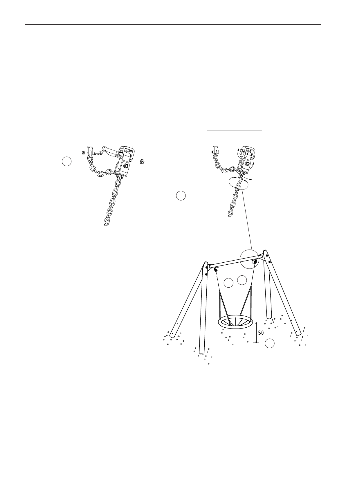
8. Hook on the swallow´s nest and pay
attention to the following notes when
doing this:
9. Attach the safety chain to the chain path
fork.
Note: The safety chain must not be taut
when the equipment is being used.
10. Check the height (top edge = 50 cm) of
the swallow´s nest when at rest.
11. Repair minor damage caused during
assembly or transportation.
12. Please ensure that all assembly aids,
e.g. excess bolts, assembly instructions,
distance battens or tape are removed
entirely from the play equipment and the
playground after work is nished.
Please note that after about 6 weeks all
screws and bolts need to be checked
and, if necessary, retightened.
a When installing joints make sure that the bolt head ts snugly into the milled slot.
b The nut has to be tightened to the end of its thread.
c Make sure that the joints move smoothly.
d Tighten the bolts until the uppermost chain link cannot be moved.
8
10
9
a
b
b
c
d
d
a
8
9