308740 7
Installation
NOTE:
Reference numbers and letters in parentheses in
this text refer to the numbers and letters in the
illustrations.
Icons in the text refer to the icons on the equip-
ment, keypad, or reference card.
Be sure all accessories are adequately sized and
pressure-rated to meet the system requirements.
For maintenance and safety, you must have a ball
valve between each fluid supply line and the ProMix
system.
See page 34 for dimensions.
CAUTION
The ProMix pot life timer will not function properly
when used with multiple guns that are operating
simultaneously. To avoid having mixed material set in
the equipment, carefully monitor the pot life by some
other means.
Location
WARNING
FIRE AND EXPLOSION HAZARD
The ProMix control is intrinsically safe
when used without any external electri-
cal components connected to it. If an
external power supply or printer is
connected to the control, the control is
no longer intrinsically safe and the
control, as well as the power supply and printer,
must not be operated in hazardous locations, as
defined in article 500 of the National Electrical
Code (USA) or your local electrical code.
If moving the ProMix with a forklift, be sure to tie the
unit securely to the forklift before lifting it. An optional
Caster Kit is available.
Setup
1. Remove the front panels from the ProMix control
(69) and the fluid section (C).
2. Tighten the fluid line connections between the flow
meter, mix manifold, and other system compo-
nents as they may have loosened during shipment.
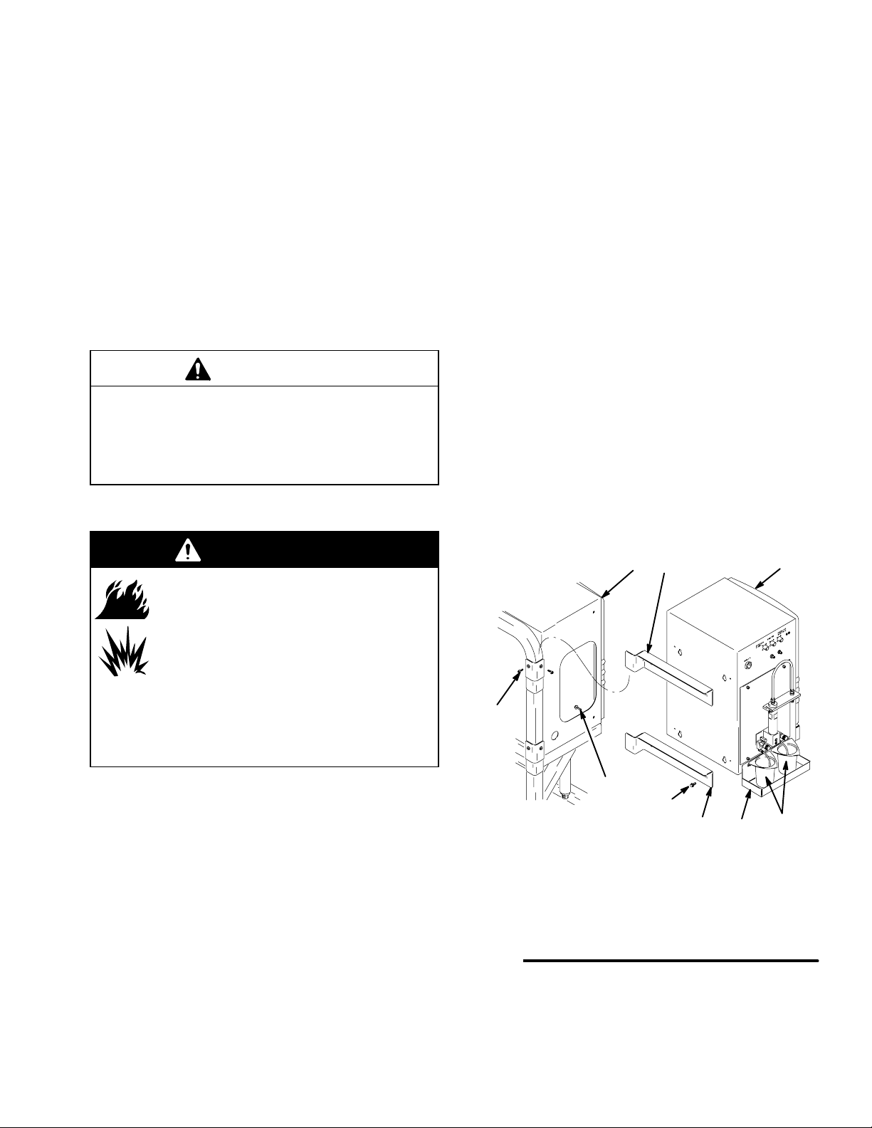
3. Connect the ProMix control (69) to the fluid section
(C). See Fig. 2.
a. Place the brackets (6) into the slots in the
ProMix fluid section (C). Loosely install the
control bracket set screws (47).
b. Connect the ProMix control (69) to the brack-
ets (6) with the screws (74).
c. Tighten the screws (41) to make the fluid
section and control sides flush. Tighten the set
screws (47) for further adjustment.
NOTE: If you choose to mount the control on a
wall, rather than connecting it to the fluid section,
make sure the mounting surface can support the
weight of the control and any hoses and accesso-
ries connected to it and any stress that may be
applied during operation. See the control manual
308783 for mounting dimensions.
d. Install the beaker tray (I) with the two screws
(included), and place the beakers (H) in the
tray.
Fig. 2
69
C
6
KEY
C Fluid Section
H Beaker
I Beaker Tray
6 Control Bracket
69 ProMix Control
74 Screw
H
6
I
7467A
74
41
47