ZWAE ONIIIS Manual

INSTALLATION AND SERVICE MANUAL
Zakład Wytwórczy Aparatów Elektrycznych Sp. z o.o.
ONIIIS
Outdoor disconnector
Manual No DTR.01.03.02.EN

Zakład Wytwórczy Aparatów Elektrycznych Sp. z o.o.
2
zwae.com.pl
WARNING!
During the operation of electrical equipment, certain parts of
these devices are normally under dangerous voltage, and me-
chanical parts, also remotely controlled, can move quickly.
Failure to follow the warning instructions can result in serious
personal injury or material damage.
Only suitably qualied personnel can work on or near the device.
This personnel must know exactly all safety rules and rules for
maintaining the device in accordance with these instructions.
The problem-free and safe operation of this device requires
proper transport, proper storage, construction and assembly as
well as careful service and maintenance.

Zakład Wytwórczy Aparatów Elektrycznych Sp. z o.o.
3
Table of contents
1. TRANSPORT AND STORAGE . . . . . . . . . . . . . . . . . . . . . . . . . . . . 4
1.1. Unpacking and inspection ..............................4
1.2. Transport and storage. ................................6
2. DESCRIPTION ........................................ 6
2.1. Application ...........................................6
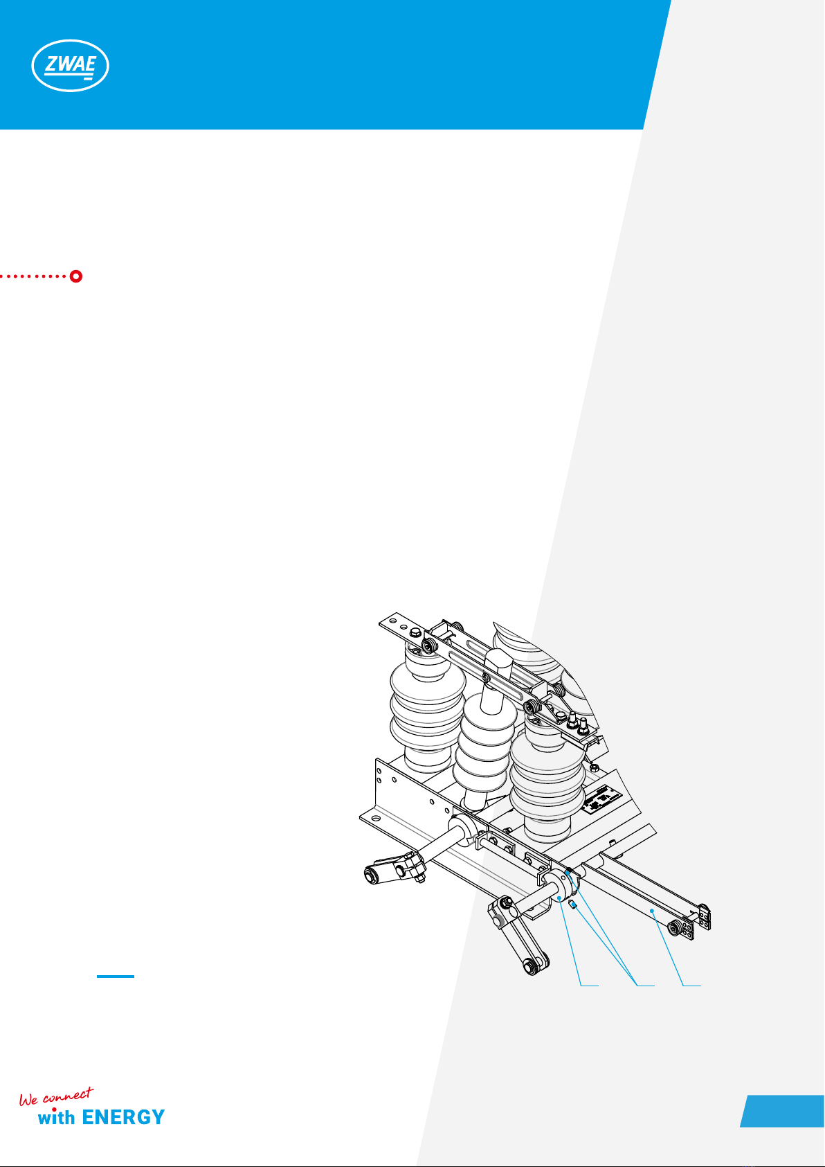
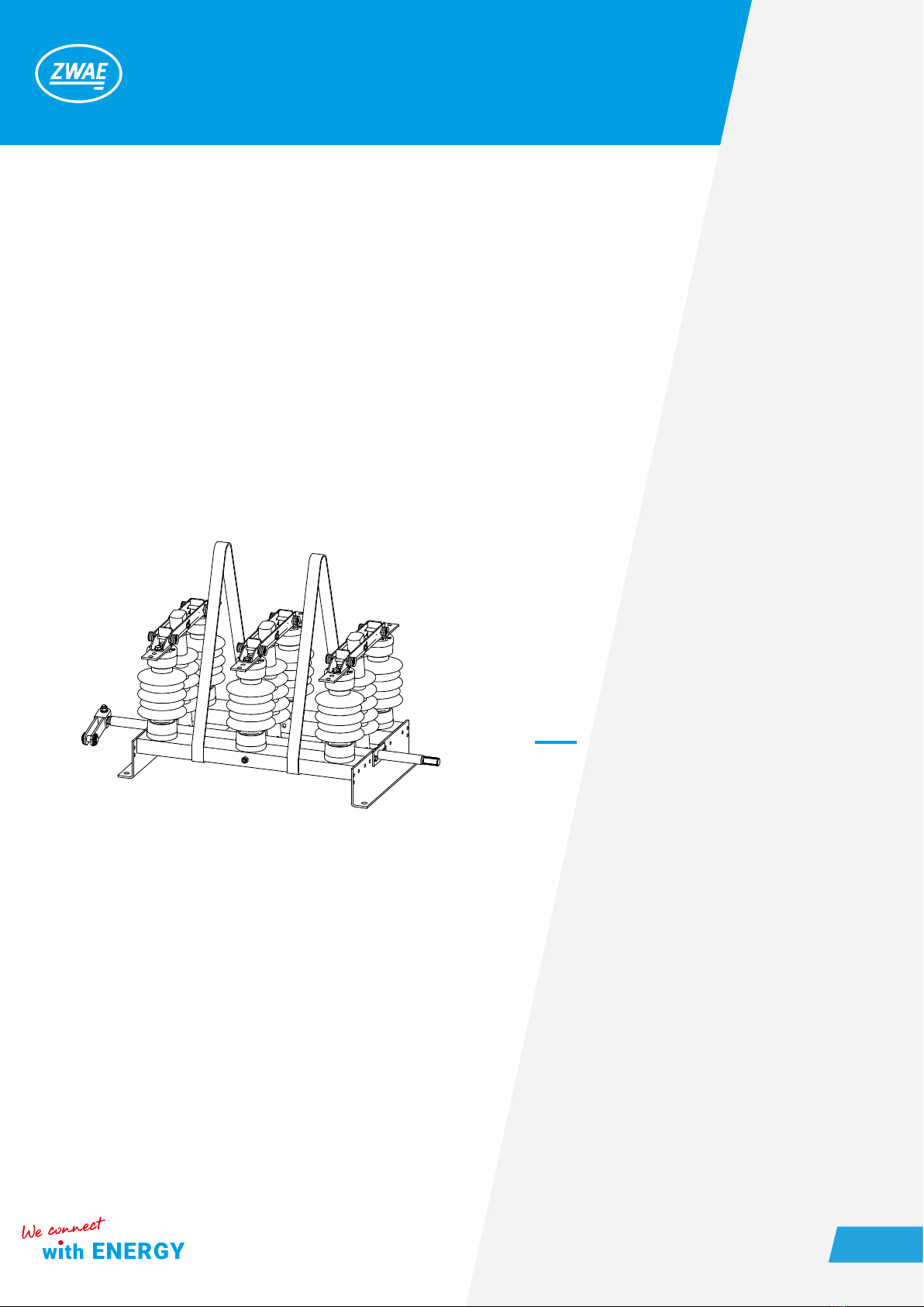
2.2. Construction and principle of operation. ..................7
2.3. Ambient conditions during operation .....................8
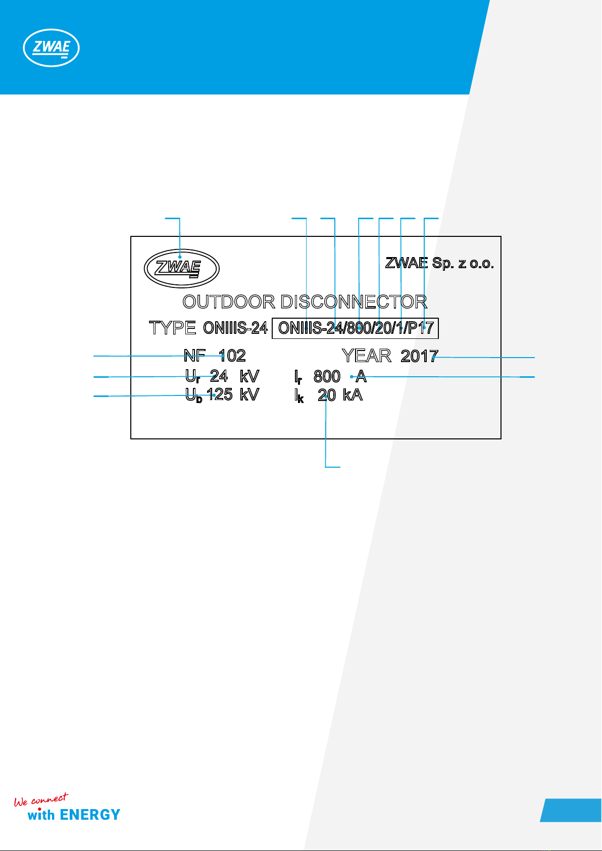
2.4 . Nameplate. ..........................................9
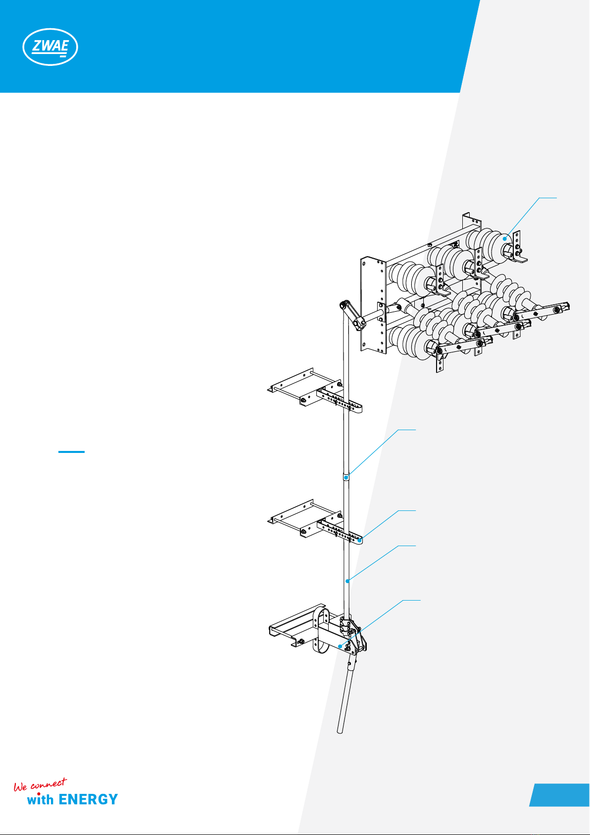
3. ACCESSORIES, ADDITIONAL EQUIPMENT ................. 10
4. INSTALLATION AND ADJUSTMENT ...................... 13
4.1. Preparation of the supporting structure and assembly
ot the disconnector........................................13
4.2. Connecting feeding wires and grounding wire .............14
5. OPERATING MANUAL ................................. 15
5.1. Periodic inspections ...................................15
5.2. Permitted repairs carried out by the user. .................16
6. MAINTENANCE ....................................... 16
6.1. Regular tests .........................................16
7. UTILIZATION ......................................... 17

Zakład Wytwórczy Aparatów Elektrycznych Sp. z o.o.
4
1. TRANSPORT AND STORAGE
1.1. Unpacking and inspection
Immediately after receiving the outdoor disconnector, the delivery's compliance with the packing list should be
checked. Then one should check whether the apparatus has not been mechanically damaged during transport
and the data on the nameplate match the order.
Disconnectors are delivered on a transport pallet, to which they are screwed. When transporting the discon-
nector, excessive shocks should be avoided. Disconnectors are delivered to the customer in a completely
assembled and adjusted condition.
Before moving the disconnector from the pallet to
another place, four screws have to be unscrewed.
Disconnector should be moved by grabbing the
base frame. It is unacceptable to lift the disconnec-
tor by grabbing the current paths.
Figure 1 ONIIIS disconnector on the transport pallet screwed with screws.

Zakład Wytwórczy Aparatów Elektrycznych Sp. z o.o.
5
WARNING !
In case of disconnector equipped with earthing knives,
the fastening screws (item 3) of the blockade ring (item
2) mounted on earthing knives's shaft, are loosen for de-
livery time, what allows the earthing knives to be closed
(with closed disconnector's current path).
After unpacking the disconnector at the recipient, the
earthing knives (item 1) should be open leaving the cur-
rent path closed and the blockade ring should be re-posi-
tioned (item 2) and the screws tightened (item 3).
1
32
Figure 2 Regulation of disconnector’s earthing switch.

Zakład Wytwórczy Aparatów Elektrycznych Sp. z o.o.
6
1.2. Transport and storage.
The disconnectors can be transported to a place of storage and installation by any means of transport. During
transport, the disconnectors should be secured against moving and colliding with each other or parts of the
vehicle. It is not allowed to set the disconnectors directly on top of each other. It may damage the disconnector.
The disconnector should be moved using straps as shown in the gure below.
Disconnectors should be stored indoors, in an atmosphere free from aggressive chemical agents.
2. DESCRIPTION
2.1. Application
The outdoor disconnectors of type ONIIIS are intended for usage in outdoor 24 kV and 36 kV switchgears. They
are designed to close and open electrical circuits in a off-load condition. In the open position disconnectors cre-
ate a visible insulation gap in the air, thus meeting the relevant requirements of standards for disconnectors.
Figure 3 The way of moving the disconnec-
tor using straps.

Zakład Wytwórczy Aparatów Elektrycznych Sp. z o.o.
7
2.2. Construction and principle of operation
The ONIIIS disconnectors are switches with a vertical movement of knifes of the current path. The base frame
of the disconnector (item 1) is a welded steel frame in which sides the main shaft (item 2) is mounted. On the
transverse shelves of the base frame there are porcelain support insulators (item 3), on which there is a dis-
connector's current path consisting of two xed contacts (item 4) bolted to the insulators and movable contact
(item 5). The movable contacts of the current path are connected to the main shaft by the driving insulator
(item 6). The rotary movement of the main shaft is transmitted through the driving insulator to the movable
contacts, causing them to move in a plane perpendicular to the base frame. The pressure of the knives on the
contacts is ensured by springs (item 7). The disconnectors have an earthing point to connect the grounding
connection (item 8).
Figure 4 Outdoor disconnector type ONIIIS-24/800 (24 kV,800 A)
8
2
1
4
75
4
3
6

Zakład Wytwórczy Aparatów Elektrycznych Sp. z o.o.
8
Ø14 Ø14
15 32
15 32
20
Ø13
40
80
17 32
Ø13
60
60
52
2.3. Ambient conditions during operation
The ONIIIS disconnectors are adapted for outdoor operation, at ambient temperature from -40 to +40 ° C and
relative humidity to 100%.
Figure 5 Types of terminals of ONIIIS type disconnector
Disconnector:
ONIIIS-24/800
ONIIIS-36/800
Disconnector:
ONIIIS-24/1600
ONIIIS-24/2000
ONIIIS-36/1600 Disconnector:
ONIIIS-24/2000
Disconnector:
ONIIIS-36/2500

Zakład Wytwórczy Aparatów Elektrycznych Sp. z o.o.
9
2.4. Nameplate
5
6
7
8
3
2
963 8 410
1
1. Manufacturer
2. Year of production
3. Rated current Ir=800 A
4. Rated duration of short-circuit tk[s]
5. Serial number
6. Rated operating voltage Ur[kV]
7. Surge test voltage Up[kV]
8. Rated short-circuit current Ik[kA]
9. Number of poles
10. Creepage distance, 17 mm/kV

Zakład Wytwórczy Aparatów Elektrycznych Sp. z o.o.
10
3. ACCESSORIES, ADDITIONAL EQUIPMENT
1. ONIIIS disconnector
2. Manual sliding operating mechanism NNP with x-
ing
3. Coupling tie rod
4. Supporting bracket
Figure 6 ONIIIS type disconnector with NNP operat-
ing mechanism mounted on the ZN pillar
1
5
4
3
2

Zakład Wytwórczy Aparatów Elektrycznych Sp. z o.o.
11
1. ONIIIS disconnector
2. NR5S manual operating mechanism with xing
3. Coupling tie rod
4. Supporting bracket
5. Clamp
Figure 7 ONIIIS disconnector with a wall-mounted
NR-5S operating mechanism
1
5
4
3
2

Zakład Wytwórczy Aparatów Elektrycznych Sp. z o.o.
12
1. ONIIIS disconnector
2. NSL-60 motor operating mechanism with xing
3. Coupling tie rod
4. Supporting bracket
5. Clamp
Figure 8 ONIIIS disconnector with NSL-60 operating
mechanism mounted on a spun pillar.
1
5
4
3
2

Zakład Wytwórczy Aparatów Elektrycznych Sp. z o.o.
13
4. INSTALLATION AND ADJUSTMENT
Persons performing switching activities should have adequate professional qualications and experience in
servicing high-voltage equipment. During moving the disconnector or its earthing switch (if equipped), the
safety regulations must be obeyed at the installation site
Before switching (closing or opening) of the disconnector or its earthing switch, one should ensure that the
switching is permissible, taking into account the conditions indicated above and the arrangement conditions
of the switchgear.
In the closed position of the disconnector, earthing switch, the lever of the operating mechanism should be
directed upwards. The actuating lever for the operating mechanism (in the case of a sliding operating mecha-
nism) must be turned downwards by 180 ° until it stops, causing the disconnector to open. When closing, the
course of action is similar, except that the lever movement takes place in the opposite direction.
4.1. Preparation of the supporting structure and assembly ot the disconnector
ONIIIS disconnectors are intended for operation in horizontal and vertical positions, with movable contacts at
the top. The design of the supporting structure should take into account keeping the appropriate insulation
level to earth, and the construction itself should have adequate stiffness.
The base frame of the disconnector should be pre-screwed in three places (with three M16 bolts), and then
optionally washers should be placed under the base frame to align the plane of the supporting structure. The
contact points between the support structure and the disconnector's base frame should lie in one plane (pos.2).
12
1. Elements of the supporting structure
2. The plane in which contact points of the
supporting structure should be located.
Figure 9 Installation of the disconnector to
the supporting structure.

Zakład Wytwórczy Aparatów Elektrycznych Sp. z o.o.
14
4.2. Connecting feeding wires and grounding wire.
Before screwing the rails, the terminals (item 3) of the disconnector should be cleaned of any contamination
by a method that does not damage the silver coatings. It is recommended to use a soft, lint-free cloth for this
purpose. Next, one should lubricate the contact surfaces of terminals and rails with a thin layer of acid-free
vaseline or other conductive grease. The screws (item 2) should be tightened carefully with a torque of 62 Nm
using two wrenches. When tightening the screws, caution must be maintained to not change the settings of
the disconnector itself. Slight change to the position of the terminal may cause the apparatus to work improp-
erly.
The earthing conductor should be connected by using a screw (item 4) (torque 54 Nm) placed in the earthing
point located on the shelf of the disconnector's base frame. The earthing point must be previously greased
with acid-free vaseline.
4
3
2
1
1. Rail
2. Terminal’s screw
3. Terminal
4. Earthing terminal screw
Figure 10 Screwing the rails and earthing
conductor

Zakład Wytwórczy Aparatów Elektrycznych Sp. z o.o.
15
zwae.com.pl
WARNING!
Before putting disconnectors into service under voltage, the
user should make sure that the assembly has been made cor-
rectly and check that the condition of the disconnectors and
operating mechanisms as well as the method and place of in-
stallation correspond to the conditions of safe operation. In par-
ticular, it is necessary to inspect the apparatus paying attention
to the condition of insulators, contacts and correct tightening of
screw connections.
Failure to perform inspection activities can lead to serious
breakdowns of switchgears. In case of difculties, adjustment
should be ordered from the manufacturer.
5. OPERATING MANUAL
During the switching operations, it is advisable to do visual inspection of disconnector in each case, paying at-
tention to the correct achievement of limit positions by the apparatus, as well as the condition of the insulators
contamination, main contacts connections and operating mechanisms condition.
In case of nding any signicant faults that could damage the disconnector or threaten the safety of operation,
the disconnector should be immediately disconnected from voltage and the faults should be removed.
5.1. Periodic inspections
It is recommended that disconnector inspections be carried out during periodic inspections of the indoor switch-
gear. During inspections should be checked in particular:
- condition of insulators, special attention should be paid to contamination of their surfaces and possible mechani-
cal damages (scratches, cracks, etc.);
- main contacts condition paying attention to possible damage (traces of melting, silver coating defects) in places
of their mutual contacts;

Zakład Wytwórczy Aparatów Elektrycznych Sp. z o.o.
16
5.2. Permitted repairs carried out by the user
Disconnector repairs performed if necessary by the user should not go beyond the adjustment of contacts and
mechanisms conditioning the proper operation of the apparatus.
More complicated repairs requiring dismantling of the disconnector can only be carried out by the manufactur-
er. The manufacturer is not responsible for the work of disconnectors repaired by the user, if the repair included
the performance of actions without consulting the manufacturer.
6. MAINTENANCE
Maintenance of the disconnector is recommended to be carried out after each inspection.
The scope of maintenance includes:
- cleaning insulators using such tools and cleaning substances that do not cause damage to their surface. For
cleaning shoud be used a soft, lint-free cloth.
- lubrication of main contacts with acid-free vaseline (or other conductive grease);
- replacement of contacts in the case when the surfaces of their mutual contact are signicantly damaged;
- tightening of loose screw connections if needed;
- complement of damaged protective coatings.
6.1. Regular tests
After the inspection, maintenance and possible repair of the disconnector, each time it is necessary to check
the correctness of apparatus mechanical action and if necessary - perform adequate adjustment of mecha-
nisms. It is also recommended, especially in the case of doubts regarding the assessment of surface damage
of the main contacts at places of their mutual contact, to additionally check the resistance of the main current
path. This is especially important for disconnectors that conduct continuous currents with values close to their
rated current. The measured resistances should not exceed the values given in the following table 1.
Measurements of resistance of disconnector's current path and isolation should be carried out in accord-
ance with the regulations in force in the power industry.

Table 1 Resistances of ONIIIS type disconnectors
7. UTILIZATION
The ONIIIS type disconnector is made of materials that are recyclable.
The main materials from which the disconnectors are built are:
- steel (painted, galvanized);
- copper (painted, silver-plated);
The disconnectors do not contain any dangerous substances. In accordance with applicable regulations, it is
possible to return a worn out, complete disconnector to the manufacturer.
Zakład Wytwórczy Aparatów Elektrycznych Sp. z o.o.
Current path resistance Disconnector 24kV Disconnector 36kV
phase
L1, L2, L3
Rmax
65 µΩ
Rmax
70 µΩ
Zakład Wytwórczy
Aparatów Elektrycznych Sp. z o.o.
Gdańska 60, 84-300 Lębork
POLAND
Address of correspondence:
Kębłowo Nowowiejskie, ul. Łąkowa 2
84-351 Nowa Wieś Lęborska
POLAND
tel.: +48 59 863 36 15
www.zwae.com.pl
Table of contents
Other ZWAE Industrial Equipment manuals