Ricoma CHT2 User manual

CHT2 MULTI-HEAD
QUICK START GUIDE:
RICOMA INTERNATIONAL CORPORATION
3450 NW 114th Ave., Miami, FL 33178
Telephone: (305) 418-4421 | Toll Free: 1-888-292-6282
www.ricoma.us
Copyright 2018 Ricoma International Corporation
All rights reserved

Ricoma Quick Start Guide2
TABLE OF CONTENTS
GETTING STARTED: MACHINE OVERVIEW
THREADING
INSTALLING THE NEEDLE
INSTALLING THE BOBBIN
HOOPS AND BRACKETS
EMBROIDERING WITH THE EXTENDED TABLE
Leveling the machine
Turning on the machine – power cord connection
Security lock
Machine head indicator lights
Start/stop button in between metal covers
Adjusting the position of the panel
Emergency stop button
6
7
7
8
8
9
10
10
11
12
14
14
15
16
21
23
17
18
18
19
20
20
20
21
How to replace a spool
Preparing your machine for threading
Threading the machine from start to nish
Selecting a needle
How to install the needle
The anatomy of the bobbin case
Inserting the bobbin
Cap rings and cap attachments
How to remove the cap driver
How to install the cap driver
Flat hoops and brackets
How to attach the at frame bracket
How to remove the at frame bracket
How to insert the hoop into the machine
How to remove the hoop from the machine
How to install the extended table
Attaching the sash frame

Ricoma Quick Start Guide 3
HOOPING
CONTROL PANEL OVERVIEW
MAINTENANCE
COMMON ERRORS
23
24
25
26
27
42
44
49
50
50
45
46
46
47
47
47
48
29
30
30
34
37
39
39
40
41
41
42
Finding the center of your design for a left-chest logo
Hooping a polo or golf shirt
Hooping a hoodie or jacket
Hooping the front or sides of a cap
Hooping the back of a cap using a round hoop
Full embroidery process from start to nish
How to change your embroidery status
Design menu
Design settings menu
Color sequence settings
Design tracing
How to adjust embroidery speed
Emb mode menu
Start-up menu/Color change mode
Manual color change/needle display
Trimming
Oiling/Lubrication
Care of the bobbin case/rotary hook area
Resolving a thread break
Replacing a needle
Bobbin running out
Emergency stop error
No needle error/color change error
Motor fault error/Main axis error
Hook timing
TENSION
Tension
Adjusting the top thread tension: Spring lever
Adjusting the top thread tension: Tension knobs

Ricoma Quick Start Guide4
TABLE OF CONTENTS
THREAD BREAKS
NEEDLES
THREAD
STABILIZER
Reasons why thread breaks occur
Thread break prevention
Thread break troubleshooting
Anatomy of the needle
How long do needles last?
How do I know when to change a needle?
Why do needles break?
Blade sizes
Needle nishes
Types of needlepoints
The difference between sharp point and ball point needles
The relationship between needles and threads
The bobbin
Types of bobbin sides
Bobbin ber choices
Top thread ber choices
Common stabilizer weights
Cut-away
Tear-away
Specialty backing
Topping
Poly mesh backing
Fusible backing
Foam
Adjusting the bobbin tension
Other factors that affect tension
51
52
53
53
54
55
55
56
56
56
57
57
58
58
59
60
60
61
63
64
64
64
64
65
65
65

Ricoma Quick Start Guide 5
EMBROIDERY TECHNIQUES
Backing and needle recommendations
Hooping placement recommendations
Specialty hoops
Cap selection
Cap digitizing
Cap sewing tips
65
67
69
70
70
70

Ricoma Quick Start Guide6
Leveling your embroidery machine is essential,
as this step will ensure your machine is secured
into place. Skipping this step may result in
injury, loss of registration of your design and
other issues.
Before leveling your machine, make sure the
four level pegs are attached to the stand legs.
See Figure 1.
To level your machine, take all four level
pegs on your machine stand and rotate them
clockwise by hand until they reach the oor.
Once the pegs have reached the oor, rotate
each nut clockwise using the provided black
wrench. Do NOT skip this important step,
as this will ensure the pegs are xed to the
ground.
Once you have tightened all four pegs, the
wheels on the machine will lift, immobilizing
it. Last, conrm the machine is secure and is
no longer able to move. Refer to the leveler
on the bottom right and left of the machine to
conrm that the machine has been properly
leveled. If the bubble is in the center of the
lines, then you have correctly completed this
step. See Figure 2.
Figure 1
Figure 2
GETTING STARTED: MACHINE OVERVIEW
Leveling the machine

Ricoma Quick Start Guide 7
The CHT2 runs on 220 volts. If you are in a country with a 220-
volt output, you can plug the machine directly into an outlet to
power it on.
If you’re in the U.S. or a country with a 110-volt electrical output,
you will need to use the transformer included with your machine
to convert the electrical output from 110 volts to 220 volts in
order to operate the machine properly.
If you’re in a country with a 110-volt output, follow these steps to
correctly turn on your machine.
1. Connect the plug on the machine’s box to the transformer.
2. Plug the transformer into an electrical outlet.
3. Turn on the transformer. See Figure 3.
4. Flip the orange switch on the machine’s box. See Figure
4.
Note: When the machine is on, the switch should be facing the back of the machine as seen in Figure 4.
Your CHT2 comes with security locks in between the machine
heads to prevent any damages during shipping. See Figure 5.
Before operating your machine, be sure to remove the locks.
Keep these locks handy in case you plan on moving your
machine to a new location in the future.
To locate the security lock, slide off the magnetic metal cover
between the heads. See Figure 6.
To remove the security lock, loosen its screws using a 4 mm
Allen wrench. You will nd a set of Allen wrenches in your toolkit.
Once the security lock is removed, return the metal cover to its
original position.
Figure 3
Figure 4
Figure 5
Figure 6
Turning on the machine – Power cord connection
Security lock

Ricoma Quick Start Guide8
The machine head indicator lights
are located on the top right of each
machine head. See Figure 7.
During working status, the machine
head indicator lights are green. If
you encounter a thread break while
embroidering, the indicator light will
ash red.
On the metal cover in between the machine’s heads, you’ll nd
start and stop buttons to make multi-head operation more
ecient. The red button is the stop button. The green button is
the start button. These buttons serve the same function as the
start and stop buttons on your panel that allow you to rewind
and forward through your design. See Figure 8.
To rewind slowly through your design, rst press the red button
to stop the machine. Then, hold the red button until you have
reached the area where you want to begin stitching again. Last,
tap the red button again to stop the machine from rewinding.
Next, locate the switch on the machine’s head. This will be
located underneath the machine head indicator light. Next, ip
the switch underneath the indicator light upward. See Figure 9.
This action will trigger a red blinking light, and tell the machine
it’s in repair mode. See Figure 10.
You can now press the green button and the design will start
again and stitch over the missed part.
Figure 7
Figure 8
Figure 9
NOTE:
Machine head indicator lights
Start/stop button in between metal covers

Ricoma Quick Start Guide 9
First, be sure to carefully remove the plastic wrap that
protects the panel. After removing it, you will nd four Allen
screws, which will allow you to adjust the placement of the
panel. See Figure 11.
Your touch-screen panel can be adjusted in two ways: up
and down or from side to side. To adjust the panel, use
the 5 mm Allen key included in your toolbox. To move the
panel from side to side, loosen the two Allen screws on the
top and bottom. Then, adjust the panel assembly until it’s
facing the desired position.
Next, tighten the screws using the 5 mm Allen key. To
move the panel up or down, loosen the two Allen screws
on the right and left. Next, adjust the panel assembly until
it’s facing the desired position. Last, tighten the screws using the 5 mm Allen key.
To fast forward slowly through your design,
press the green button only after you have
pressed the red button. Then, press the
red button to stop the machine from fast
forwarding. Press the green button again to
begin stitching from the desired point.
Note:
Figure 10
Figure 11
Adjusting the position of the panel

Ricoma Quick Start Guide10
Because your machine comes pre-threaded, you will only need
to replace the spools at rst rather than threading the machine
from the very beginning. To do so, clip the thread from the
existing thread spool. Make sure you clip the thread right above
the spool and not inside the thread path. See Figure 13.
Then, replace the existing spool with a new spool. Next, take the
loose end of the thread from the existing spool and tie it to the
loose end of the new thread in a simple knot. See Figure 14 and
15. Repeat this process on all spools before proceeding.
Now, go to the front of your machine and make sure the threads are separated on their individual thread
paths. Next, unthread the needle and pull each thread carefully
all the way through until you no longer see any of the old thread.
While you pull the thread, you’ll see the new thread and the knot
you created traveling through the thread path. Continue to pull
until you see the knot you created reaches past the needle bar.
Now, clip the thread right above the knot, and repeat the process
on all remaining needles. Once you have completed all needles,
it’s time to thread the needle. Pass the thread through the eye of
the needle starting from the front to the back. Once you made
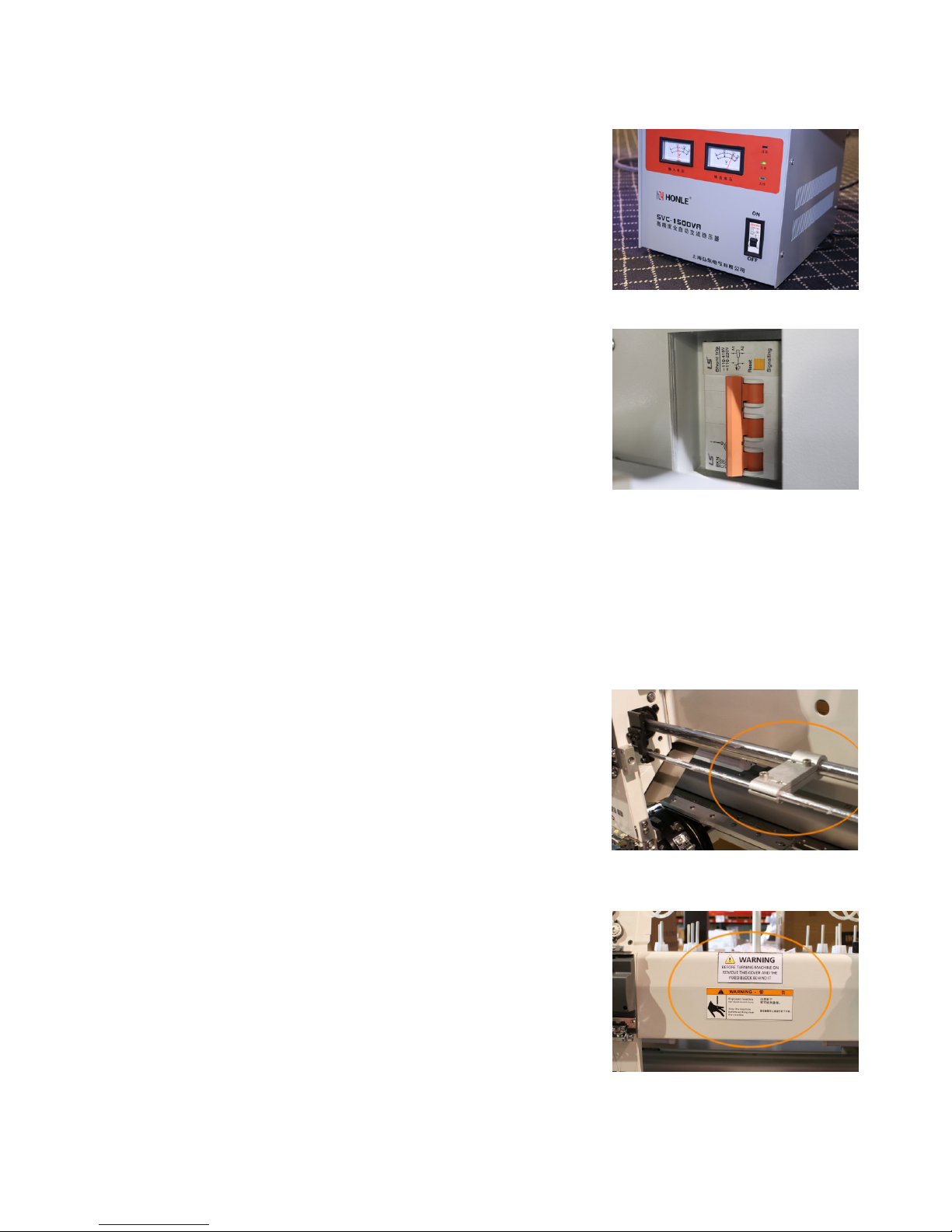
In case of an emergency, press the red emergency stop button
located on the metal cover in between the machine’s heads. Hitting
this button will kill the power immediately. To restart the machine,
rotate the knob clockwise following its directional arrows. The knob
will then release, allowing the machine to be powered on again. Keep
in mind, you need to turn your machine back on to commence. To
turn your machine back on, click on the orange reset button located
next to the power switch. Then, ip the power switch back on. See
Figure 12.
Figure 12
Figure 13
Figure 14
THREADING
Emergency stop button
How to replace a spool

Ricoma Quick Start Guide 11
sure your thread has gone through the needle, pass the thread
down the presser foot. Now, you can rest your thread on the
spring. You should leave about two inches of thread hanging
and trim the excess.
Keep in mind: The color spools will need to be placed in the
same order on all heads. For example, if you place the white
thread on needle 1 on one head, you need to place the white
thread on needle 1 on the remaining heads as well.
TIP:
The thread tubes will be used during the threading process.
These tubes carry the thread from the thread rack to the
machine’s head. Your machine comes pre-threaded with these
tubes in place.
In the future, you may need to remove the tubes to thread your
machine from scratch. To reattach them, attach one end of the
tube to the slot just below the top thread tension knob. Then,
attach the other end of the tube to the slot on the machine’s
head. You may nd it easiest to work from the center out. Guide yourself by counting the slots on the
top and bottom to make sure you are attaching the tubes to their corresponding slots. The rst slot on
the top should go with the rst slot on the bottom and so forth. See Figure 16.
Your welcome kit contains two boxes of embroidery thread. You will need 15 spools of thread for each
of the machine’s heads. If you haven’t done so yet, remove the wrappers on the provided thread spools.
To release the tail of the thread, unsnap the base of the cone,
and unwind until the thread is completely out of the base.
To begin threading your machine, place each thread spool onto
the spool pins. The spool pins are the 15 pins secured with grey
foam and a clear plastic reel behind each of the machine heads.
Before positioning the spools, see Figure 17 to view which
thread spool pin corresponds with each needle.
Figure 15
Figure 16
Figure 17
Preparing your machine for threading

Ricoma Quick Start Guide12
1. Thread each spool through the eyelets on the upper thread
rack until they reach the top tension knobs. S e e F i g u r e 1 9 .
2. Next, pass the thread through the small eyelet located
behind the rst tension knob. Position the thread to the
right side of the top tension knob in between the tension
disks, making sure the thread is inside the tab at the 3
o’clock position. To ensure you’ve completed this step
correctly, make sure the metal plates on the tension knob
are touching after you’ve positioned the thread. See Figure
20.
3. Unhook the thread tube from each side. Next, using the
included threading tool from your toolkit, hook the thread
to the end of the tool and feed the thread through the
plastic tube. Once the thread has been fed through the
tube, unhook the thread. See Figure 21.
4. Reattach the thread tube to each end.
To thread your machine from the very beginning, follow these
simple steps. You will use the eyelets on the thread rack to guide
the thread in a straight path toward the rst tension knob. Make
sure the thread passes through each eyelet. You will need to
thread the rst three cones in order from back to front. Then,
repeat this order with the next three cones and so forth. See
Figure 19.
Before threading, you should be familiar with the thread path.
The back row of thread will be threaded through the back metal
rack. The middle row of threads will be threaded through the
middle metal rack. And the front row of threads will be threaded
through the front metal rack. See Figure 18.
TIP:
Figure 18
Figure 20
Figure 21
Figure 19
Threading the machine from start to finish

Ricoma Quick Start Guide 13
5. Pass the thread through the clip located just above the
top tension knobs. Be sure to gently pull the clip up with
your nger, rather than just sliding the thread under the
clip to avoid damaging the thread and threading the
machine incorrectly. See point A in Figure 22.
6. Next, pull the front disk of the tension knob toward you,
and slip the thread to the right side of the knob. You will
know which path to follow for each needle by using the
numbers as guides. The photo displays the thread path
for needle 14. See point B in Figure 22.
7. Locate the post right above the corresponding thread
break wheel (these are the white wheels on the machine’s
head.) Pass the thread through the left side of the post.
See point C in Figure 22. Then, guide the thread to the
right and wrap it around the thread break wheel. See the
path from point C to E in Figure 22. Make sure you make
one full clockwise rotation until the thread exits through
the left side of the bottom post. See point E in Figure 22.
8. Place the thread under the bottom clip by pulling the clip
up. Slide the thread underneath. See point F in Figure 22.
9. Next, you will thread the check spring and the lever arm.
Begin by lifting the lever to place the check spring into
threading position if it isn’t already. Now, coming down
from the right side, pass the thread over the outer right
side of the rollers and then in through the opening in the
center. See point G in Figure 23. Next, pass the thread
through the spring from the right to the left. See point H
in Figure 23. Then, take the thread and pull it through the
opening in the center and out over the outer left side of
the rollers. Continue pulling the thread up until you reach
the lever arm. See point I in Figure 23.
10. Now, pass the thread through the opening of the lever
arm from the right to the left. See point I in Figure 23.
Then pass the thread back down until it runs through
the ceramic eyelet. See point J in Figure 23. Continue
running the thread down the same path until it passes
through the following ceramic eyelet. See point K in
Figure 22
Figure 23
Figure 24
A
B
C
D
E
F
F
G
K
L
H
I
J

Ricoma Quick Start Guide14
TIP:
INSTALLING THE NEEDLE
Selecting a needle
Choosing the right needle is important to ensure quality stitches. Embroidering with a needle that is
too small or too big for the thread and/or fabric may result in thread breaks or skipped stitches. There
are three things to consider when choosing the right needle for the job: nish, size and point. DBxK5 is
an established standard system for machine embroidery. This style needle has a medium point with a
larger eye, which allows the thread to ow smoothly and helps reduce thread breaks. Its only downfall
is that it is slightly less durable due to its thinner eye wall. A size 75/11 sharp point needle will work for
most embroidery projects. However, a general rule of thumb is to use ball point needles for knits and
sharp point needles for woven fabrics.
Tip:
Figure 24.
11. Now it’s time to thread the needle. Pass the thread through the eye of the needle from the front to
the back. To ensure your needle is placed correctly, make sure the curved side is facing the back.
Then, pass the thread through the presser foot. See point L in Figure 24.
12. Now, you can pull the thread back up, and rest your thread on the spring until you’re ready to
embroider. We recommend leaving one to two inches of thread hanging and trimming the excess.
This is optional, but will eliminate the need to snip the thread tail that will remain after the rst
stitch is made while the thread tail is still held on the spring. See Figure 24.
13. Last, take a step back and look at the front of the machine to make sure that all needles appear to
be threaded correctly. If they seem to be uniform, you are ready to stitch a test pattern.
How to install the needle
When changing a needle, make sure the scarf of the needle is facing away from you and toward the
machine. When inserting the needle make sure it is completely straight and not slanted. If the needle is

Ricoma Quick Start Guide 15
not positioned correctly, the machine will not work properly, and the needle will break.
Tip:
The anatomy of the bobbin case
Figure 26Figure 25
INSTALLING THE BOBBIN
Before threading the bobbin and inserting the bobbin into the machine, be familiar with the parts of the
bobbin case that will be referenced.
Figure 27

Ricoma Quick Start Guide16
Inserting the bobbin
1. If you haven’t done so yet, remove the bobbin case from the machine’s bobbin housing unit. To do
so, simply lift the latch and pull the bobbin case toward you.
2. Pull out the empty or nearly empty bobbin and discard or rewind.
3. Insert the bobbin into the bobbin case, making sure the thread is running clockwise. See Figure
28.
4. Pass the thread through the bobbin case slit. See Figure 29.
Figure 28 Figure 29
5. Pull the bobbin thread under the tension arm, making sure the thread exits at the notch on the
other end. See Figure 30.
6. To ensure the bobbin is placed correctly, turn the bobbin case to the other side, and pull on the
thread. The bobbin thread should still be running clockwise in this direction, and you should see
the letters rotating clockwise. See Figure 31.
Figure 30 Figure 31

Ricoma Quick Start Guide 17
Figure 32 Figure 33
7. Wrap the thread around the small pigtail on the bobbin case. See Figure 32.
8. Grab the bobbin case while lifting the latch, and insert it into the machine. Make sure the thread
tail is no longer than 3 inches. A longer tail can wrap around the shaft and create a build-up of
thread. See Figure 33.
HOOPS AND BRACKETS
Cap rings and cap attachments
When sewing caps, you will need to use the following materials:
the cap driver, the cap station, a cap ring, a blank cap and backing
(usually tear-away).
The cap driver is the accessory that is mounted on the machine.
See Figure 34. This tool holds the cap and cap ring during the
sewing process.
The cap station is the tool that holds the cap ring (the cap hoop)
while hooping. The cap station should be mounted on your
machine stand or on a sturdy table. See Figure 35.
Once you have mounted the cap station, you can attach the cap
ring to the cap station to begin hooping.
The cap ring is the hoop for your caps. See Figure 36. This ring
can be adjusted depending on the thickness of the cap’s fabric.

Ricoma Quick Start Guide18
To do so, loosen the screw on the bottom right of the cap
ring using a Phillip screwdriver. Tighten the screw once
you have reached the desired position for the band.
How to remove the cap driver
How to install the cap driver
1. 1. Using the 4 mm Allen wrench included in your toolkit, loosen the hex screws that connect the
cap driver to the pantograph.
2. To remove the cap driver, carefully pull the cap driver toward you using both hands. Keep in mind:
It’s not necessary to completely remove the screws. It should be able to slide off easily if you
have loosened both hex screws.
3. Repeat this process with the remaining heads.
1. First, select the cap hoop on your control panel. You will nd the preset hoop function under the
Design Settings menu. Once you have selected the preset cap hoop, the pantograph will move
forward.
2. If you haven’t done so already, make sure the at support bracket is removed. To remove the
bracket, loosen the hex screws that attach the bracket to the pantograph rail.
3. Insert the cap driver on the machine, making sure the
sewing arm goes through the opening in the back of the cap
driver. Each cap driver and cap ring is numbered. Use the cap
driver labeled “1” for head 1. Use the cap driver labeled “2” for
head 2, and so on.
4. The cap driver is equipped with four small wheels that
slide onto the rail underneath the sewing arm of the machine.
Position the cap driver in line with the railing, making sure all the
wheels are aligned. See Figure 37.
Figure 37

Ricoma Quick Start Guide 19
Flat hoops and brackets
5. Slide the cap driver in though the machine’s sewing until it reaches the pantograph.
6. Line up the slots on each end of the cap driver bracket with the hex screws and the slots on the
inside of the cap driver bracket with the support pins on the pantograph rail.
7. Tighten the hex screws using the 4 mm Allen wrench to secure the cap driver to the pantograph.
8. Repeat this process on the remaining heads.
Your Ricoma CHT2 Series embroidery machine includes a set of 10 hoops per head. There are ve
different sizes ranging from A to E. Hoop A is the smallest hoop and hoop E is the largest hoop. You
will receive 8-24 of each hoop depending on the amount of heads your machine comes with. You will
also receive one sash frame with your machine. For information on installing the sash frame, refer to
the section on how to install the sash frame.
A general rule of thumb most embroiderers follow when selecting hoops is to use the smallest hoop
that your design will t in without hitting the frame. When you upload your design, you will be able to use
the preset hoop feature on the machine to make
sure your design is within the frame.
Selecting the smallest hoop your design ts in
creates the best hooping tension for your fabric,
eliminating thread breaks, puckering and other
machine embroidery issues. Whenever you are
using a square or rectangular hoop, the only
places you are really getting a grip on the fabric
is in the corners. In contrast, round hoops have
equal holding power all around the circle.
Figure 38

Ricoma Quick Start Guide20
How to attach the flat frame bracket
How to remove the flat frame bracket
How to insert the hoop into the machine
In order to run ats on your machine, you will rst need to connect the at frame bracket onto the
pantograph rail. This bracket will support your hoops when embroidering on at garments such as
polo shirts.
1. Locate the at frame bracket that comes with your machine.
When attaching the bracket to the pantograph rail, make the
curved side of each bracket arm is facing the inside and the at
side is facing the outside. See Figure 39.
2. Slide the bracket onto the pantograph rail, lining up the
slots on the ends of the bracket with the hex screws and the
slots on the inside of the bracket with the support pins. See
Figure 40.
3. Secure the bracket to the pantograph rail of the machine
using the 4 mm Allen wrench.
Note:
Figure 39
Figure 40
You will need to remove the at frame bracket when using the extended table or when embroidering
on caps. To remove the at bracket, loosen the arms by rotating the screws counterclockwise with
the 4 mm Allen wrench. Then, pull the arms straight out toward the front of the machine.
Note:
The metal arms of the hoops are designed to slip under the clips on the hoop brackets. To correctly
insert the hoop onto the brackets, make sure the open-ended slot (the U-shaped notch) is facing the
machine. You should see the U shape on the top edge of the hoop, and it should always be on the
right side. See Figure 41.
Table of contents
Other Ricoma Sewing Machine manuals

Ricoma
Ricoma TCS1501 User manual

Ricoma
Ricoma 8S User manual

Ricoma
Ricoma RCM 1501 PT User manual

Ricoma
Ricoma RCM-1201TC-7S User manual

Ricoma
Ricoma EM-1010 User manual

Ricoma
Ricoma SWD Series User manual

Ricoma
Ricoma EM-1010 User manual

Ricoma
Ricoma MT-1502 User manual

Ricoma
Ricoma RCM-1201PT User manual

Ricoma
Ricoma EM-1010 User manual