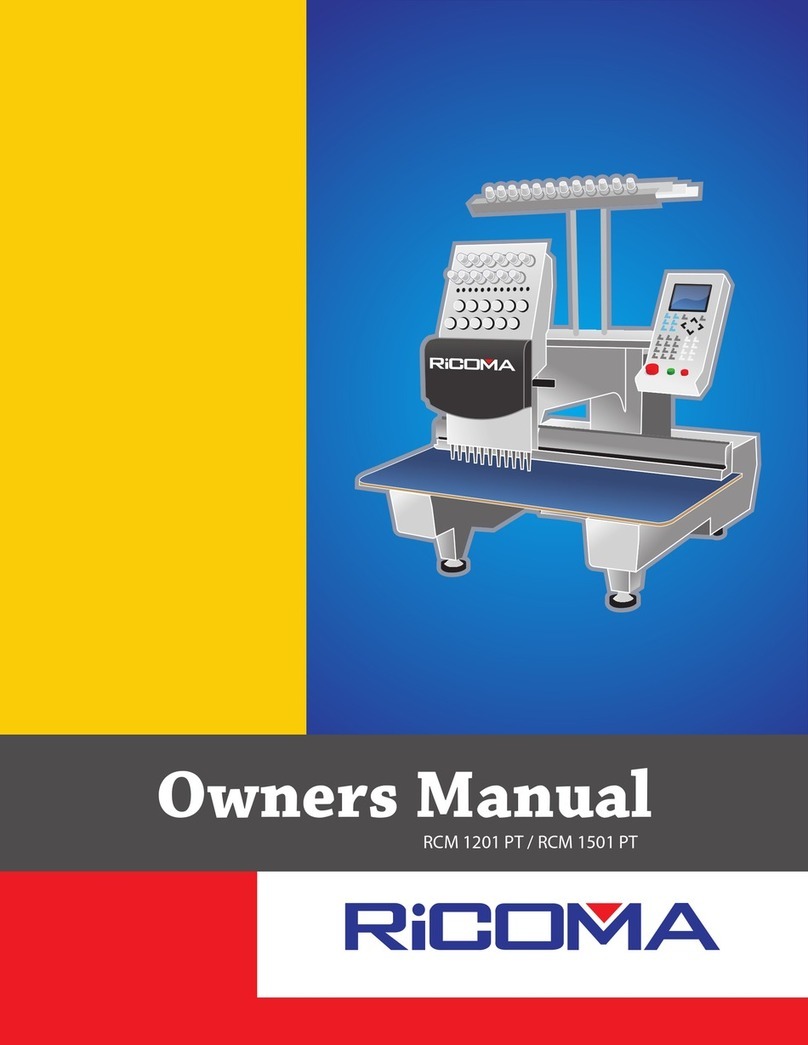
Ricoma RCM-1201PT User manual

RCM-1201PT
Operating Manual

Index
BECS-09 Singular-head Computerized Embroidery Machine I
INDEX
Part I Features....................................................................................................1
Part II Control and Basic Operations ................................................................5
2.1 CONTROL PANEL .................................................................................................5
2.2 MAIN SCREEN.....................................................................................................7
2.3 DEFINITION AND BASIC OPERATION OF KEYS ...................................................10
2.4 INDICATOR LIGHT OF MAIN SHAFT STOP POSITION ...........................................14
2.5 START AND STOP BUTTON .................................................................................14
Part III Basic Knowledge and Operation ........................................................15
3.1 WORK MODE,EMBROIDERY MODE AND WORK SEQUENCE ..............................15
3.2 DESIGN INPUT FROM THE DISK AND STARTING THE FIRST EMBROIDERY ...........18
3.3 SELECT MEMORY DESIGN FOR EMBROIDERY ....................................................24
Part IV Setting Parameters ....................................................................................28
4.1 PARAMETER MENU ...........................................................................................28
4.2 REAL TIME ROTATION AND SCALING UP/DOWN.................................................29
4.3 SETTING REPETITION EMBROIDERY ..................................................................34
4.4 OFFSET POINT...................................................................................................38
4.5 CYCLIC EMBROIDERY .......................................................................................40
4.6 WORK SEQUENCE .............................................................................................41
4.7 STANDARD EMBROIDERY DATA PARAMETER.....................................................44
4.8 STANDARD TRIM PARAMETERS .........................................................................47

Index
II BECS-09 Singular-head Computerized Embroidery Machine
4.9 STANDARD MACHINE PARAMETERS .............................................................. 48
4.10 COMMON PARAMETERS............................................................................... 53
Part V Manual Operation ............................................................................ 55
5.1 ORIGIN BACK................................................................................................ 55
5.2 STOP BACK ................................................................................................... 55
5.3 MAIN SHAFT ORIGIN..................................................................................... 56
5.4 MANUAL TRIM .............................................................................................. 56
5.5 FRAME RANGE .............................................................................................. 56
5.6 EMBROIDER RANGE ...................................................................................... 58
5.7 EMBROIDER A LINE ....................................................................................... 59
5.8 FORWARD CODE FLOAT................................................................................. 60
5.9 BACKWARD CODE FLOAT.............................................................................. 61
5.10 FORWARD STI.FLOAT.................................................................................. 61
5.11 BACKWARD STI.FLOAT ............................................................................... 62
Part VI Disk Management........................................................................... 64
6.1 LIST FLOPPY/USB DISK DIRECTORY ............................................................ 64
6.2 DISK DESIGN INPUT ...................................................................................... 65
6.3 PC COM DESIGN INPUT ............................................................................... 69
6.4 DELETE USB/FLOPPY DISK DESIGN ............................................................. 69
6.5 DES.OUTPUT TO FLOPPY/USB DISK ............................................................ 70
6.6 FORMAT DISK................................................................................................ 72

Index
BECS-09 Singular-head Computerized Embroidery Machine III
Part VII Memory Design Operation...........................................................74
7.1 ENTER THE MEMORY DESIGN OPERATION MENU..............................................74
7.2 SELECT DESIGN FOR EMBROIDERY ...................................................................75
7.3 SHOW MEMORY DESIGN ...................................................................................77
7.4 DISK INPUT .......................................................................................................79
7. 5DELETE MEMORY DESIGN................................................................................80
7. 6EDIT BAT C H DESIGN ........................................................................................81
7. 7COPY DESIGN...................................................................................................87
7. 8COMBINE DESIGN ............................................................................................89
7. 9DIVIDE DESIGN ................................................................................................92
7. 10 CLEAR ALL ....................................................................................................95
7. 11 CHECK DESIGN ..............................................................................................96
7. 12 RENAME FILE.................................................................................................97
7. 13 EXPAND SATI N ...............................................................................................98
7.14 DESIGN LETTER PATTERN ................................................................................99
Part VIII Assistant Function ................................................................................102
8.1 SET SOFT LIMIT...............................................................................................102
8.2 FRAME RESTORE.............................................................................................104
8.3 DEFAULT SETUP ..............................................................................................104
8.4 SWITCH TO THE ENGLISH LANGUAGE .............................................................105
8.5 SET FRAME ORIGIN.........................................................................................105
Index
IV BECS-09 Singular-head Computerized Embroidery Machine
8.6 MACHINE SELF-TEST AND TEST MACHINE PARTS ....................................... 106
Appendix.......................................................................................................... 108

Part I Features
BECS-09 Singular-head Computerized Embroidery Machine 1
Part I Features
1. Equipped with LCD
This machine model uses LCD as monitor. Both words and icons are used
in the operation window to help fast learning and easy operation. The design
picture can be displayed simultaneously with embroidery.
2. Input and output of disk-stored designs
From the built-in floppy disk drive, the user can directly input the designs
data in the following formats into the memory: files in binary system (.dsb),
ternary system (.dst) and Z coding system (.dsz) from Tajima format disk, and
files in binary system, ternary system and Z coding system from Barudan
format disk. And it is also possible to output the design data of binary system
from the memory to Tajima format disk.
3. Storage capacity for design data
The built-in storage can keep 99 designs and the stored maximum stitches
are 1,000,000.
4. Rotating speed control
Press the keys to adjust the current rotating speed of the main shaft between
150 rpm and the highest speed, and the current value will show in the screen.
And the average highest rotating speed for flat embroidery is 1000 rpm.
5. Real time scaling up/down and design rotation
While embroidering the designs in memory, the user can scale up/down the
design 50% to 200% separately in vertical and horizontal directions.

Part I Features
2 BECS-09 Singular-head Computerized Embroidery Machine
Meanwhile the user can rotate the design freely in a circle by choosing one of
the eight coordinate directions and adding an angle degree between 0° and 89°.
6. Thread break detecting
In parameter setting, the user can select thread break detecting or no thread
break detecting. When it’s effective, the machine will stop automatically and
show an icon in the screen when thread break happens.
7. Work sequence
The “work sequence” parameter decides how to deal with color change
codes.
8. Over-frame protection
It’s to prevent the frame from exceeding the normal scope to cause a
collision accident.
9. Auto origin return
With this function, the frame will return to the origin point upon
completion of embroidering.
10. Positioning idling
The frame can move fast forward or backward to the desired position by
setting a function code or a certain stitches to move without embroidering,
which will let the machine to start embroidery from anywhere.
11. Repetition embroidery function
There can be maximal 99 times of repetition for one design in each of
vertical and horizontal directions.
12. Periphery operation
This is to show or idle around the border of the design which has been
scaled up/down, rotated or repetition embroidered.

Part I Features
BECS-09 Singular-head Computerized Embroidery Machine 3
13. Scaling up/down and rotating the design
It is to embroider the design after scaling up/down and/or rotate it.
14. Design operation
With this, the user can survey the memory directory and the information of
design files in the directory. And the user can delete, copy, combine or divide
the designs.
15. Disk management
It is to list the design files, input/output files and format the disk.
16. Error information
In case of wrong operations or machine malfunctions, the screen will show
words or icons to inform you.
17. Frame protection
When the frame has changed its position after power-off during
embroidering or after stopping the machine, it will be unable to continue the
former embroidery. If the frame protection has already been set as effective, the
user can restore the frame position to continue embroidery via the operation
“Frame restore”.
18. Adjusting the stop position (parameter “Set brake Para”)
It is to adjust the stop position of the main shaft to suit different machines.
The parameter is available to change, and the more its value is, the larger
additional degrees the main shaft will stop with.

Part I Features
4 BECS-09 Singular-head Computerized Embroidery Machine
19. Returning and patching
When the thread breaks, the user can choose automatic return of a certain
stitches or press the stop button for manual return. When the machine arrives at
the start point for patching, press start button to patch.
The stitches of automatic return can be set.
20. Combining design
A new design can be created by combining several designs with their
different parameter setting. Thus the combined designs can be embroidered
together.
21. Cyclic embroidery
With this function the machine will automatically return to the origin point
to start again after embroidering one design.
22. Offset point
It’s to set an offset point anywhere away from the start point. This will
facilitate the operations such as fabric-changing and trimming.
23. Chinese-English switch
Choose the desired language to suit different customers.
24. Trimming
In embroidery the user can choose the automatic trimming according to the
function codes or stopping the machine to manual trim.

Part II Control and Basic Operations
BECS-09 Singular-head Computerized Embroidery Machine 5
STI
51
Part II Control and Basic Operations
2.1 Control Panel
# 01
COL: 3
STI: 11791
PF
X: + 123.5
Y: + 201.1
9

Part II Control and Basic Operations
6 BECS-09 Singular-head Computerized Embroidery Machine
Start button Stop buttonEmergency-Stop button

Part II Control and Basic Operations
BECS-09 Singular-head Computerized Embroidery Machine 7
2.2 Main Screen
Following power-on, the machine will start up and display the main screen.
In the main screen there are 9 areas for icon display: , , , , ,
, , and I. The screen shows as follows:
xxxxx
Definition of the above areas (A-I):
: It’s for the current system mode. The icon “ ” means embroidery
preparation mode and “ ” means embroidery confirmation mode.
The mode “ ” is for preparation work; and in this mode the user can
press the start button to begin embroidery. After that, it’s no longer allowed to
select design, input scale and repetition parameters, delete memory-stored
designs, clear all designs in the memory, move frame around the design range,
embroider the design range, save origin points, restore frame position, restore
default setting, etc.
STI
300
51
01: 1 . 2 . 3 . 4 .
# 01
COL: 3
STI: 11791
A B C
D
E F G
X: + 123.5
Y: + 201.1
Design No.
Color Change Count
Stitches
X Displacement
Y Displacement
HI

Part II Control and Basic Operations
8 BECS-09 Singular-head Computerized Embroidery Machine
Press the embroidery confirmation key “ ” to switch between the
embroidery preparation mode “ ” and the embroidery confirmation mode
“”.
: It displays the color change and start mode. The color change and start key
“” on keyboard is to switch among the following three modes: auto color
change auto start “ ”, auto color change manual start “ ” and manual color
change manual start “ ”.
C: It is for embroidery mode: normal embroidery “ ”, low-speed idling
“”or high-speed idling “ ”. Press the key “ ” to switch among them.
It shows the current needle position. Press the number key to change
color and the current needle position will show in this area, e.g. press the
numerical key “9” to change from the color 1 to color 9, and this area will
show “ 9”.
E: If the cyclic embroidery function is closed, there will be corresponding
icon display in this area. Otherwise it will show “ ”
F: This is to show whether the design is set with scaling up/down or rotation.
The icon “ ”will show here if these parameter values are standard: scales
(: 100%, : 100%), design direction: , rotation angle: 0). Otherwise it
will show “ ”
G: It shows the repetition embroidery. “ ” will appear when no
repetition (each of and normal repetitions is set as 1). If there is

Part II Control and Basic Operations
BECS-09 Singular-head Computerized Embroidery Machine 9
repetition (normal repetition)it shows “ ”
I: It shows the special operations or causes of machine stop during
embroidery.
“”It comes to the stitch skip codes during embroidery.
“”It comes to the color change codes during embroidery.
“”Embroidery comes to an end.
“”The machine returns to the start point.
“”The machine stops because thread break is detected during
embroidery.
“”The machine stops because the stop button is pressed.
“”The machine stops after it returns and then patching embroiders
to the thread break point.
The following items are also shown in the main screen:
1. Design number: it’s the number of the memory-stored design (like "#01"
in the above picture), which is ready for embroidery immediately after start-up.
The user can select another design number by entering design operation (press
“” to enter it). And the system will remind the user whether to renew the
current one after inputting a new design from the disk (press “ ” to enter the
disk operation).
2. Stitches: There are "11791" stitches for the #01 design in the above

Part II Control and Basic Operations
10 BECS-09 Singular-head Computerized Embroidery Machine
picture.
3. Embroidery speed: It shows the current set value of rotation speed when
there is no embroidery and for an instant when the user presses the acceleration
key “ ” or deceleration key “ ”. It shows the current rotation speed
during embroidery, like "300" in the above picture.
4. Stitch count: It counts the stitches since the last clearance of the number,
like "51" in the above picture. Press the key “ ” on the panel and press
“ ” to confirm. Then select “Clear Add Stitch” to reset the count. Otherwise
press “ESC" to exit operation.
5. Frame coordinate: It can set the last design’s frame position as the zero
point of coordinates, like “X+123.5 Y-201.1” in the above picture. Press the
key “ ” on the panel, select the second option “Clr Frame Coordinate”
and confirm by pressing “ ”, so as to reset the coordinate value.
Otherwise press “ESC” to exit.
2.3 Definition and Basic Operation of Keys
1) Function key:
—Disk operation
This is for all the operations concerning the disk, including listing designs
in floppy/USB disk, inputting floppy-disk/USB designs into memory, inputting
design data into memory by PC COM port, deleting disk designs, outputting
design data to floppy/USB disk, formatting floppy/USB disk, etc.
CL
CL

Part II Control and Basic Operations
BECS-09 Singular-head Computerized Embroidery Machine 11
—Design operation
This is for all the operations concerning the design (files/data), including
selecting design, memory-stored design display, inputting design from floppy
disk, editing batch design, clearing all designs,
deleting/copying/combining/dividing memory-stored design, renaming design
file, expanding satin and create letter design. Please read Part VII.
—Parameter operation
It’s for parameter setting and has two pages. One is for design parameter
operations, including scaling up/down, design direction, rotation angle,
repetition priority, repetition times, repetition interval, offset origin, cyclic
embroidery and work sequence. The other page is for standard data, trim and
machine parameters, and common parameters. The user can select any of them
to enter the next level of menus for setting. Please refer to Part IV.
—Manual operation
This key is for all manual operations, including showing frame operations
and positioning floating, etc. Please refer to Part V for details.
—Switch key for working methods
Press this key to switch between “manual color change and startup”
(without application of work sequence) and “embroidering in the set work
sequence”. When the machine embroiders in the set work sequence, the

Part II Control and Basic Operations
12 BECS-09 Singular-head Computerized Embroidery Machine
sequence is displayed in highlight together with the icon “ ” in the main
menu. Otherwise, the sequence is displayed in low light together with the icon
“” in the main menu.
— Assistant function
It includes default setup, language choice, etc. All operations for assistant
function are set by this button. Please refer to Part VIII.
— Embroidery method
Press this key to switch among normal embroidery, high-speed floating and
low-speed floating.
Numerical keys
Keys “+/-.019” are used to input design number, design name and
various data parameters.
“ ” is used for inputting special operations such as design name input.
“ ”Clearing
The key is used for clearing fault information or data such as stitch count
and frame coordinates.
“ESC”Exit key
Before confirmation in all operations, press this key to end operation and
return to the upper menu. Keep pressing the key to return to the main screen.
“ ”Confirmation key
It’s used for confirmation of various operations and data.
CL

Part II Control and Basic Operations
BECS-09 Singular-head Computerized Embroidery Machine 13
2) Manual frame-moving key
“ ”switch between two frame-moving speeds
It has two different speeds: high speed “ ” and low speed “ ”.
Press this key to switch between them.
—Frame-moving keys
In the main menu, press one of the above keys to move the frame to the
pointed direction before embroidery starts. Or press two neighboring keys at
the same time to move the frame in the direction of the angle bisector.
In all function and menu operations, press “ ” to move the
cursor in the horizontal direction or to turn page while pressing “ ”
move the cursor in the vertical direction.
3Direct control key
“ ”Speed deceleration key
Use this key to set the embroidery rotating speed.
In the main menu, 10 rpm is reduced for each time of pressing this key.
Keep pressing it and the rotation speed will decrease until 150 rpm.
“ ”Speed acceleration key
In the main menu, 10 rpm is raised for each time of pressing this key. Keep
pressing it and the rotation speed will rise until the set highest speed. The
highest speed for standard embroidery is between 650 rpm and 1000rpm.
PU PD
PU PD

Part II Control and Basic Operations
14 BECS-09 Singular-head Computerized Embroidery Machine
Note: Only “ ” and “ ” can be used during embroidery.
2.4 Indicator Light of Main Shaft Stop Position
It is to show whether the main shaft has stopped in the “stop area”. The
light is on when the main shaft stops in the area. Otherwise the light is off. The
main shaft has to stop in the “stop area” before starting embroidery, returning,
moving frame, etc. The user can manually turn the shaft to the position.
2.5 Start and Stop Button
The start button (green) is on the operation box and it’s for starting
embroidery.
The stop button (red) lies on the operation box, and it’s for stopping
embroidery.
Start button: Press it to start embroidering forward when the machine stops;
when the machine has stopped press the button for a single return of 10 stitches
and the machine will return continuously while the user keeps pressing the
button.

Part III Basic Knowledge and Operation
BECS-09 Singular-head Computerized Embroidery Machine 15
Part III Basic Knowledge and Operation
3.1 Work Mode, Embroidery Mode and Work Sequence
1. Work mode
The machine has two modees: embroidery preparation and embroidery
confirmation. The icon“ ” means the system is currently in embroidery
preparation mode and the icon“ ” means the system is currently in
embroidery confirmation mode.
Under “ ” mode, the user can prepare for embroidery; after entering the
“” mode, the user can start embroidery. Then it’s no longer permitted to
select design, input scale and repetition parameters, etc. which will affect the
design embroidery.
Under “ ” mode, press the key“ ” to enter the embroidery confirm
mode; under “ ” mode, press the key“ ” and “ ” to enter the
embroidery preparation mode.
When a design is input into the memory under “ ” mode, the machine
will automatically enter the embroidery confirmation mode“ ”. And then
embroidery will start when the startup button is pressed.
In menu operations of this system, the available options are in highlight
while the unavailable options are in darkness.
2. Embroidery method and returning for patching
The machine has the following embroidery methods: normal embroidery,
low-speed floating and high-speed floating. The icon“ ” is for normal
Table of contents
Other Ricoma Sewing Machine manuals

Ricoma
Ricoma 8S User manual

Ricoma
Ricoma CHT2 User manual

Ricoma
Ricoma TCS1501 User manual

Ricoma
Ricoma EM-1010 User manual

Ricoma
Ricoma EM-1010 User manual

Ricoma
Ricoma SWD Series User manual

Ricoma
Ricoma MT-1502 User manual

Ricoma
Ricoma RCM-1201TC-7S User manual

Ricoma
Ricoma EM-1010 User manual

Ricoma
Ricoma RCM 1501 PT User manual