Ricoma SWD Series User manual

Ricoma Quick Start Guide2Ricoma Quick Start Guide 3
TABLE OF CONTENTS
EMBROIDERING WITH THE EXTENDED TABLE
How to install the extended table .................................................................................................................21
Hooping and attaching the sash frame........................................................................................................22
How to hoop the sash frame.........................................................................................................................22
Attaching the sash frame..............................................................................................................................23
HOOPING
Centering a left-chest logo ............................................................................................................................23
Hooping recommendations ..........................................................................................................................24
Hooping at garments...................................................................................................................................25
Hooping the front or sides of a cap ..............................................................................................................25
Hooping the back of a cap using a round hoop ...........................................................................................26
CONTROL PANEL OVERVIEW
Full embroidery process from start to nish................................................................................................28
How to change your embroidery status .......................................................................................................29
Design menu ..................................................................................................................................................29
How to import and select a design ..............................................................................................................29
How to export a design..................................................................................................................................30
How to delete a design from your machine’s memory ............................................................................... 30
Onboard Lettering ..........................................................................................................................................31
Hoop Selection...............................................................................................................................................31
Design Settings Menu ...................................................................................................................................32
Color Sequence Settings...............................................................................................................................35
Design Tracing ...............................................................................................................................................37
Embroidery Speed..........................................................................................................................................38
Directional Arrows .........................................................................................................................................38
Frame Shift Direction/Speed Increments.....................................................................................................38
Stitch Mode/Emb Mode ................................................................................................................................39
Floating Menu ................................................................................................................................................39
Manual Color Change/Needle Display..........................................................................................................40
Return to Stop Point ......................................................................................................................................40
Trimming ........................................................................................................................................................40
GETTING STARTED: MACHINE OVERVIEW
Machine Contents............................................................................................................................................ 6
Machine Components .....................................................................................................................................8
Machine Setup ................................................................................................................................................. 9
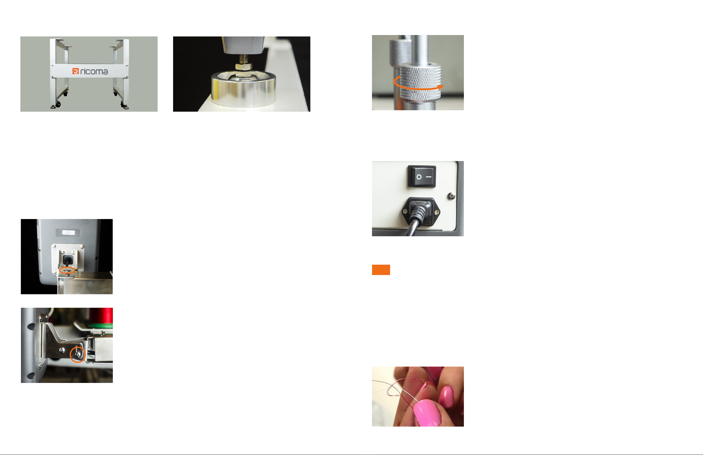
Assembling the Stand ....................................................................................................................................9
Adjusting the position of the panel...............................................................................................................10
Raising the thread rack..................................................................................................................................11
Turning on the machine – power cord connection......................................................................................11
THREADING
How to replace a spool..................................................................................................................................11
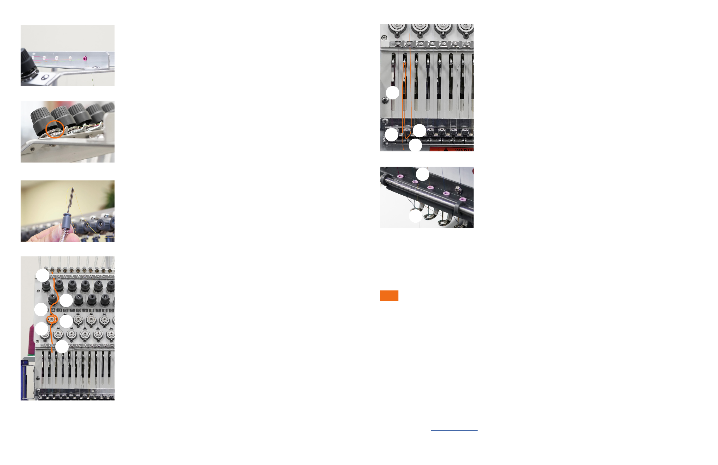
Threading the needle .....................................................................................................................................12
Threading the machine from start to nish..................................................................................................12
INSTALLING THE NEEDLE
Selecting a needle..........................................................................................................................................15
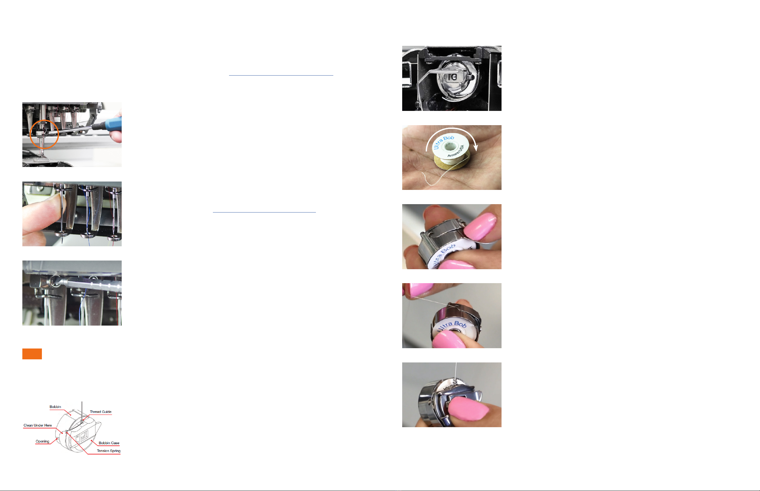
How to install the needle...............................................................................................................................16
INSTALLING THE BOBBIN
The anatomy of the bobbin case ..................................................................................................................16
Inserting the bobbin.......................................................................................................................................17
HOOPS AND BRACKETS
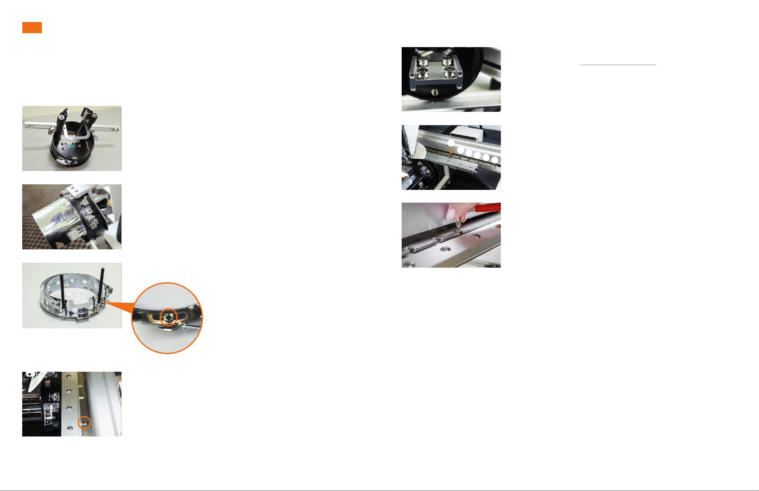
Cap rings and cap attachments....................................................................................................................18
How to remove the cap driver .......................................................................................................................18
Installing the cap driver.................................................................................................................................19
Flat hoops and brackets................................................................................................................................19
How to attach the at frame bracket............................................................................................................20
How to remove the at frame bracket..........................................................................................................20
How to insert the hoop into the machine..................................................................................................... 20
How to remove the hoop from the machine.................................................................................................21

Ricoma Quick Start Guide4Ricoma Quick Start Guide 5
TABLE OF CONTENTS
MAINTENANCE
........................................................................................................................................................................41
COMMON ERRORS
Resolving a thread break...............................................................................................................................43
Replacing a needle.........................................................................................................................................44
Bobbin running out ........................................................................................................................................44
Emergency stop error ....................................................................................................................................45
No needle error...............................................................................................................................................45
Main axis not at 100 ......................................................................................................................................45
Hook timing....................................................................................................................................................46
TENSION
Testing Tension..............................................................................................................................................47
Adjusting the top thread tension: Spring lever.............................................................................................48
Adjusting the top thread tension: Tension knobs ........................................................................................49
Adjusting the bobbin tension........................................................................................................................49
THREAD BREAKS
Reasons why thread breaks occur................................................................................................................51
Thread break prevention................................................................................................................................51
Thread break troubleshooting.......................................................................................................................52
NEEDLES
Anatomy of the needle ..................................................................................................................................53
Needle Lifetime ..............................................................................................................................................53
Needle Break Causes.....................................................................................................................................54
Blade sizes .....................................................................................................................................................54
Needle nishes...............................................................................................................................................55
Types of needlepoints ...................................................................................................................................56
The relationship between needles and threads ...........................................................................................57
THREAD
Thread consumption......................................................................................................................................57
The bobbin .....................................................................................................................................................58
Types of bobbin sides....................................................................................................................................58
Bobbin ber choices ......................................................................................................................................59
Top thread ber choices................................................................................................................................60
STABILIZER
Stabilizer colors .............................................................................................................................................62
Stabilizer weights ..........................................................................................................................................63
Common stabilizer weights...........................................................................................................................63
Types of Stabilizer .........................................................................................................................................63
Cut-away.........................................................................................................................................................63
Tear-away .......................................................................................................................................................64
Specialty backing...........................................................................................................................................64
Topping...........................................................................................................................................................64
Foam...............................................................................................................................................................64
Poly mesh backing.........................................................................................................................................64
Fusible backing..............................................................................................................................................65
EMBROIDERY TECHNIQUES
Specialty hoops .............................................................................................................................................65
Cap embroidery..............................................................................................................................................66
Operating speeds for caps and ats ............................................................................................................67
Hooping placement recommendations........................................................................................................ 68
Backing and needle recommendations........................................................................................................69

Ricoma Quick Start Guide6Ricoma Quick Start Guide 7
Package Contents
Toolbox Contents
11 hoops 1 sash frame
1 cap driver 2 cap rings 1 cap station 1 set of bracket arms
Power cord Ethernet cable Toolbox and
welcome kit
GETTING STARTED: MACHINE OVERVIEW
Machine Contents
Small round mouth
bottle
Phillips screwdriver
Nipper pliers
Three double end
wrenches
Set of nine
hexagonal wrenches
Pair of thread clippers
Flat screwdriver
One pack of needles
Cleaning brushBobbin caseUSB driveSewing machine oil
Spare parts including but not limited to screws, springs,
reciprocators, needle bar guides, pickers and bobbin
Amann starter kit

Ricoma Quick Start Guide8Ricoma Quick Start Guide 9
Machine Head Indicator Light
The machine head indicator light is located on the top right of the
machine head. See Figure 5.
During working status, the machine head indicator light is green.
If you encounter a thread break while embroidering, the indicator
light will ash red.
Step 1: Attach the connecting plates
• Unpack and unwrap the stand columns, Ricoma connecting plates
and tools. Remove all protective covering and plastic wrap and
discard.
• Place the stand columns upside down.
• Attach the Ricoma connecting plates to the stand columns upside
down using the hex head screws tted with a lock-washer and
washer. Secure with the Allen wrench. See Figure 6.
Step 2: Attach the casters
• Next, remove the protective cover on the caster’s screw, and fasten
the caster to its corresponding slot, which can be found on the at
column that connects the stand legs to each other.
• After rotating the caster clockwise, secure the hex nut using the
provided open-end wrench. See Figure 7.
• Repeat these steps for the remaining three casters.
ASSEMBLING THE STAND
Machine Set Up
Figure 5
Figure 6
Figure 7
Step 3: Attach the level pegs
Next, take all four level pegs on your machine stand and rotate
them counterclockwise by hand until they reach the oor. Once
they reach the oor, continue to rotate using the open-end wrench
to secure them tight. See Figure 8.
Once all four pegs are tight, the wheels will lift, and the machine
stand will no longer be able to slide with the wheels.
Figure 8
Machine Stand
Your embroidery machine includes a heavy duty steel stand
designed to support your machine during the embroidery process.
Assemble the stand if you plan on using it to support your machine.
If you don’t plan on using the stand, make sure your machine is
placed on a sturdy surface with enough space to embroider.
Control Panel
Your embroidery machine contains a touch-screen panel to
facilitate operation. Before operating your machine, make sure
to adjust the position of the control panel to your liking. You may
learn more about the panel features in the Control Panel Overview
section.
Thread Rack
Your embroidery machine contains a thread rack that will hold your
thread and feed the thread through the machine’s thread path.
Before threading your machine, be sure to raise the thread rack.
Emergency Stop Button
In case of an emergency, press the emergency stop button located
on the bottom left side of the panel. See Figure 4.
To restart the machine, rotate the knob clockwise following the
directional arrows. The knob will then release, allowing you to
press start.
Machine Components
Figure 3
Figure 2
Figure 1
Figure 4

Ricoma Quick Start Guide10 Ricoma Quick Start Guide 11
How to Adjust The Panel From Side to Side
1. To move the panel from side to side, loosen the screw located on
top of the panel arm. See Figure 11.
2. Then, adjust the control panel until it’s facing the desired position,
and tighten the screw.
How To Adjust the Panel Up or Down
1. To move the panel up or down, loosen the screw located on the
side of the panel arm. See Figure 12.
2. Adjust the control panel until it’s facing the desired position, and
tighten the screw.
1. Rotate the knobs on the sides of the thread rack support
counterclockwise to loosen them. See Figure 13.
2. Lift the thread rack as far up as possible, making sure both
sides of the rack remain even as it rises.
3. Rotate each knob clockwise to secure the rack into place.
Step 4: Attach the machine to the stand
Once all of the pegs and wheels are in place, turn the stand right-side-up. See Figure 9.
Last, place the machine on the stand, aligning the machine’s feet to the silver mounts on the stand.
We recommend 2-3 people to complete this step. See Figure 10.
Your touch-screen panel can be adjusted up and down or from side to side. To comfortably operate
your machinery, you may adjust the panel using the Phillips screwdriver included in your tool box.
Before adjusting the position of the panel, remove the plastic wrap that protects the panel.
Your machine comes pre-threaded, which means that you will not have to thread your machine from
scratch when you rst receive your machine. The directions below explain how to replace a spool.
Follow steps 3&4 to add a new spool when your machine arrives pre-threaded.
The power socket is located on the back left of the machine’s body.
Connect your power cord into the socket displayed in Figure 14.
Then, plug the power cord into a power outlet.
We highly recommend using a power supply (surge protector)
rather than connecting the cord directly into the wall. The power
switch can be found above the power socket.
1. Clip the thread from the thread spool you wish to replace. Make
sure you clip the thread right above the spool and not inside the
thread path.
2. Remove the old spool from the spool pin, and place a new spool
in its place.
Figure 9
Figure 11
Figure 12
Figure 13
Figure 14
Figure 15
Figure 10
ADJUSTING THE POSITION OF THE CONTROL PANEL
RAISING THE THREAD RACK
TURNING ON THE MACHINE: POWER CORD CONNECTION
HOW TO REPLACE A SPOOL
Tip: If possible, raise the thread rack on both sides while adjusting it. This will ensure it is positioned evenly.
THREADING
Adding/Replacing a Spool

Ricoma Quick Start Guide12 Ricoma Quick Start Guide 13
3. Take the loose end of the thread from the old spool and tie it to
the loose end of the new spool with a tight knot. See Figure 15.
4. Next, grab the thread from above the presser foot and pull it
carefully through until you no longer see any of the old thread.
While you pull the thread, you’ll see the new thread and the knot
you created traveling through the thread path. Continue to pull
until the knot you created passes the last point in the thread path
before the needle. See Figure 16.
5. Last, clip the thread right above the knot. Then, pass the thread through the eye of the needle and
through the presser foot. See the Threading the Needle section for more information.
Figure 16
Your machine comes with needles already installed. To learn how to replace a needle, see the Installing
the Needle section.
Before threading your machine, make sure you have raised the thread rack and properly inserted the
spools and thread tubes.
See Raising the Thread Rack in Machine Setup.
Threading the Needle
Threading the Machine from Start to Finish
1. Pass the thread through the eye of the needle from the front to
the back. Then, pass the thread through the presser foot.
2. Pull the thread up, and place the thread on the spring until you’re
ready to embroider. We recommend leaving one to two inches of
thread hanging and trimming the excess. See Figure 17.
Attach one end of the tube to the slot just below the top thread
tension knob. Attach the other end of the tube to the slot on the
machine’s head. Guide yourself by counting the slots on the top
and bottom to make sure you are attaching the tubes to their
corresponding slots. The rst slot on the top connects to the rst
slot on the bottom and so forth. See Figure 18.
1. Remove the wrapper on the thread spool. Your welcome kit contains one box of embroidery thread
to get you started. The machine can carry 15 spools of thread.
Before threading, you should be familiar with the thread path. The
back row of thread will be threaded through the back metal rack.
The middle row of threads will be threaded through the middle
metal rack. The front row of threads will be threaded through the
front metal rack. See Figure 19.
1. Thread each spool through the eyelets on the upper thread rack until they reach the top tension knobs.
See Figure 20.
2. Release the tail of the thread by unsnapping the base of the cone,
and unwinding the thread until it is completely out of the base.
3. Place each thread spool onto the spool pins.
Figure 17
Figure 18
Figure 19
HOW TO THREAD THE NEEDLE
RAISE THE THREAD RACK
ATTACH THE THREAD TUBES
PLACE THE SPOOLS
BEGIN THREADING
Note: Your machine package includes 1,000 meter thread spools. You
may remove the plastic spool holders when using these smaller thread
spools, as they do not require them. You may place the spool holders
back on when switching to full-size 5,000 meter thread spools. These
smaller thread spools do not require the plastic spool holder.
Smaller
Spool
Larger
Spool
Tip: To avoid using the wrong color, avoid placing similar colors like black and navy blue close to
each other.

Ricoma Quick Start Guide14 Ricoma Quick Start Guide 15
2. Next, pass the thread through the small eyelet located behind the
rst tension knob. Position the thread to the right side of the top
tension knob in between the tension disks, making sure the thread is
inside the tab at the 3 o’clock position. To ensure you’ve completed
this step correctly, make sure the metal plates on the tension knob
are touching after you’ve positioned the thread. See Figure 21.
3. Unhook the thread tube from each side. Next, using the included
threading tool from your toolkit, hook the thread to the end of the tool
and feed the thread through the plastic tube. Once the thread has
been fed through the tube, unhook the thread. See Figure 22.
4. Reattach the thread tube to each end.
5. Pass the thread through the clip located just above the top tension
knobs. Be sure to gently pull the clip up with your nger, rather than
just sliding the thread under the clip to avoid damaging the thread or
threading the machine incorrectly. See point A in Figure 23.
6. Next, pull the front disk of the tension knob toward you, and slip the
thread to the right side of the knob. Use the numbers as guides to
know which path to follow for each needle. The photo displays the
thread path for needle 14. Notice the tension knob is aligned just
above the needle number. See point B in Figure 23.
7. Locate the post right above the corresponding thread break wheel
(these are the white wheels on the machine’s head.) Pass the thread
through the left side of the post. See point C in Figure 23. Then, guide
the thread to the right and wrap it around the thread break wheel. See
the path from point C to E in Figure 23. Make sure you make one full
clockwise rotation until the thread exits through the left side of the
bottom post. See point E in Figure 23.
8. Place the thread under the bottom clip by pulling the clip up. Slide the
thread underneath. See point F in Figure 23.
9. Next, thread the check spring and the lever arm. Begin by lifting the
spring lever to place the check spring into threading position. Now,
coming down from the right side, pass the thread over the outer right
side of the rollers and then in through the opening in the center. See
point G in Figure 24.
10. Next, pass the thread through the spring from the right to the left.
See point H in Figure 24.
11. Then, take the thread and pull it through the opening in the center
and out over the outer left side of the rollers. Continue pulling the
thread up until you reach the lever arm. See point I in Figure 24.
12. Now, pass the thread through the opening of the lever arm from the
right to the left. See point I in Figure 24.
13. Then pass the thread back down until it runs through the ceramic
eyelet. See point J in Figure 24. Continue running the thread down
the same path until it passes through the following ceramic eyelet.
See point K in Figure 25.
14. Pass the thread through the eye of the needle from the front to the
back, and then in through the presser foot. See point L in Figure 25.
15. Last, take a step back and look at the front of the machine to make
sure that all needles appear to be threaded correctly. If they are
uniform, you are ready to stitch a test pattern.
Figure 20
Figure 21
Figure 22
Figure 23
Figure 24
Figure 25
Tip: If you run out of thread completely on a needle, re-thread, matching the thread path to a correctly
threaded neighboring needle.
A
K
L
B
C
D
E
F
G
H
I
J
INSTALLING THE NEEDLES
Choosing the right needle is important to ensure quality stitches. Embroidering with a needle that is
too small or too big for the thread and/or fabric may result in thread breaks or skipped stitches.
DBxK5 is an established needle system for machine embroidery. A DBxK5 size 75/11 sharp point
needle will work for most embroidery projects. This style needle has a medium point with a larger eye,
which allows the thread to ow smoothly and helps reduce thread breaks.
In some instances, you may need to choose a different size needle depending on your embroidery
project. Go to the Needles section to learn more about selecting the proper needle for your embroidery.
Selecting a Needle

Ricoma Quick Start Guide16 Ricoma Quick Start Guide 17
When changing a needle, make sure the scarf of the needle is facing away from you and toward the machine.
When inserting the needle, make sure it is completely straight and not slanted. If the needle is not positioned
correctly, the machine will not work properly, and the needle will break. Refer to needle diagram on page 53.
Before threading and inserting the bobbin into the machine,
see Figure 29 to view the parts of the bobbin case that will be
referenced.
Installing a Needle
The Anatomy of the Bobbin Case
Threading and Inserting the Bobbin
HOW TO INSTALL THE NEEDLE
1. Loosen the set screw above the needle with a straight slot
screwdriver. Loosen only enough to be able to remove the needle.
See Figure 26.
2. Discard the old needle in a sharp-safe container.
3. Needles have a long groove on the front and a short half-moon-shaped
section called the scarf on the rear. With the long groove facing
the front of the machine, insert the new needle by placing the point
through the presser foot, and then insert the shank into the needle bar
all the way. See Figure 27. Refer to needle diagram on page 53.
4. Verify that the long groove of the needle is still facing forward.
Tighten the needle screw while holding the needle rmly to keep
it from slipping down. See Figure 28.
1. If you haven’t done so yet, remove the bobbin case from the
machine’s bobbin housing unit. Lift the latch and pull the bobbin
case toward you to remove it. See Figure 30.
2. If there is already a bobbin in the bobbin case, pull out the bobbin
and discard.
3. Insert a new bobbin into the bobbin case, making sure the thread
is running clockwise. See Figure 31.
5. Pass the bobbin thread through the bobbin case slit.
See Figure 32.
6. Pull the bobbin thread under the tension arm, making sure the
thread exits at the notch on the other end. See Figure 33.
7. Wrap the thread around the small pigtail on the bobbin case.
See Figure 34.
8. Grab the bobbin case while lifting the latch, and insert it into the
machine. Make sure the thread tail is no longer than 3 inches.
A longer tail can wrap around the shaft and create a buildup of
thread.
Figure 26
Figure 27
Figure 28
Figure 29
Tip: To help you place the needle correctly, you may insert a wooden
toothpick into the eye of the needle. Never place a metal object in
the needle’s eye, as it could scratch the eye of the needle, causing
thread breaks.
Tip: To ensure the bobbin is placed correctly, turn the bobbin case to
the opposite side, and pull on the thread. The bobbin thread should
still be running clockwise in this direction, and you should see the
letters rotating clockwise.
INSTALLING THE BOBBIN
Figure 30
Figure 31
Figure 32
Figure 33
Figure 34

Ricoma Quick Start Guide18 Ricoma Quick Start Guide 19
HOOPS AND BRACKETS
Your machine can embroider ats and caps. Flats refer to garments like shirts and jackets that you
can lay at and hoop using your at brackets. You will embroider caps using the cap attachment. The
cap attachment is curved to match the curvature of a cap.
When embroidering caps, you will need to use the included cap
driver, cap station and cap ring.
The cap driver is the accessory that is mounted on the machine.
See Figure 35. This tool holds the cap and cap ring during the
sewing process.
The cap station is the tool that holds the cap ring (the cap hoop)
while hooping. The cap station should be mounted on your machine
stand or on a sturdy table. See Figure 36. Once you have mounted
the cap station, you can attach the cap ring to the cap station to
begin hooping.
The cap ring is the hoop for your caps. See Figure 37. This ring can
be adjusted according to the thickness of the cap using the screw
on the right-hand side.
1. Using the Phillips screwdriver included in your toolkit, loosen the
screws that connect the cap driver to the pantograph.
See Figure 38.
2. Pull the cap driver toward you using both hands.
1. Select the cap hoop from the list of preset hoops on the control
panel. Refer to the Control Panel Overview section for more
information. Once you have selected the preset cap hoop, the
pantograph will move forward.
2. If you haven’t done so already, make sure you have removed the
at support brackets. To remove the brackets, loosen the Allen
screws that attach the brackets to the pantograph rail.
3. Insert the cap driver onto the machine, making sure the sewing
arm goes through the opening in the back of the cap driver.
4. The cap driver is equipped with four small wheels that slide onto
the rail underneath the sewing arm of the machine. Position the
cap driver in line with the railing, making sure all the wheels are
aligned. See Figure 39.
5. Push the cap driver toward the machine until it reaches the
pantograph. You will attach the cap driver to slot 6 on each end
of the pantograph. See Figure 40.
6. Tighten the Phillip screws to secure the cap driver to the
pantograph. See Figure 41.
Your Ricoma SWD Series embroidery machine includes a set of 11 hoops. There are six different hoop
sizes, ranging from A to F. Hoop A is the smallest hoop and hoop F is the largest hoop.
When selecting your hoop, use the smallest hoop that your design will t into without hitting the hoop.
When you upload your design, you will be able to use the preset hoop feature on the machine to make
sure your design is within the hoop.
Cap Attachments
Installing the Cap Driver
Flat Hoops and Brackets
Removing the Cap Driver
Figure 35
Figure 36
Figure 37
Figure 39
Figure 40
Figure 41
Figure 38 Tip: It’s not necessary to completely remove the screws. It should be
able to come off easily if you have loosened both screws.
Tip: Selecting the smallest hoop your design ts into creates the best hooping tension for your fabric,
eliminating thread breaks, puckering and other machine embroidery issues.
6
54321

Ricoma Quick Start Guide20 Ricoma Quick Start Guide 21
In order to run ats on your machine, you will rst need to connect the at frame brackets onto the
pantograph rail. This bracket will support your hoops when embroidering on at garments such as
polo shirts.
To remove the flat brackets, loosen the arms by rotating the
screws counterclockwise with a 4mm Allen wrench. Then,
pull the arms straight out toward the front of the machine.
See Figure 44.
The metal arms of the hoops are designed to slip under the clips on
the hoop brackets. To correctly insert the hoop onto the brackets,
make sure the open-ended slot (the U-shaped notch) is facing the
machine. See Figure 45.
To remove the hoop, lift the hoop arms to release the pressure on the notched areas. The hoop
brackets will hold the hoops very tightly at rst, but it will gradually become easier to lift the hoop
from the bracket as you pull the hoop out.
1. Attach hoops A-E to slots 5 and 6 on each side of the
pantograph rail.
2. Attach hoop F to slots 1 and 2 on each side of the pantograph rail.
3. Attach the brackets to the corresponding slots on the pantograph
rail. See Figure 42.
4. The brackets are composed of two metal plates with a slot in
between them. When you attach the brackets to the machine,
make sure the pantograph rail is positioned in between the two
metal plates and the screws are lined up with the slots.
See Figure 43.
1. Slide the table onto the machine body and rest it comfortably on the table support brackets. See
Figure 48. Use the openings as a guide to help you see where to position the table. The sewing arms
should rest in between the table openings. See Figure 49.
Your embroidery machine includes a table designed for embroidery
on larger areas and heavier garments. See Figure 47.
Attaching the Flat Frame Brackets
Removing the Flat Frame Brackets
Inserting the Flat Hoops
Removing the Flat Hoops
Installing the Extended Table
Figure 42
Figure 43
Figure 44
Figure 45
Figure 46
Figure 47
Figure 48 Figure 49
Insert the hoop into the brackets, making sure the edge of the
hoop slips under the recessed notch at the end of the clip. The
notches in the hoop should hold securely under the prongs.
See Figure 46.
EMBROIDERING WITH THE EXTENDED TABLE

Ricoma Quick Start Guide22 Ricoma Quick Start Guide 23
Figure 50
Figure 55
Figure 51
Figure 56
Figure 59 Figure 60
Figure 52
Figure 57 Figure 58
Figure 53
Figure 54
2. After you’ve made sure your table is in place, take the
two magnetic table support legs, and place them in their
corresponding slots underneath the table. See Figure 50.
3. Level the table support legs by rotating each peg
counterclockwise until they reach the oor. Then, tighten each
nut. See Figure 51.
4. Using a Phillips screwdriver, attach the brackets on each end
of the table to the brackets on each side of the machine’s body.
See Figure 52.
5. Locate the security latches underneath the table. Tighten each
latch until the rubber stop meets the bottom of the table. You
should hear it click into place. See Figure 53.
Hooping and Attaching the Sash Frame
Centering a Left-Chest Logo
HOW TO HOOP THE SASH FRAME
HOW TO ATTACH THE SASH FRAME
1. Place the stabilizer over the frame, ensuring the stabilizer covers
all areas of the frame. See Figure 54.
2. Place the fabric over the stabilizer, ensuring both the fabric and
stabilizer cover all areas of the frame. See Figure 55.
3. Smooth out the surface of the fabric, and snap the metal clamps
onto each of the short sides of the frame. See Figure 56.
1. Place the hooped sash frame over the extended table and clip back any excess fabric that may
interfere with the pantograph rail. See Figure 59.
2. Attach the sash frame to the last two slots on the pantograph rail. Use a Phillips screwdriver to
secure the screw. See Figure 60.
Before hooping your garment, you must determine the proper placement of the design. To determine
where to place the design, you must rst nd the center of the design.
Keep in mind: The center will vary on the size of the garment you are embroidering and the size of the
design you are stitching.
4. Smooth out the surface of the fabric, and snap the remaining
metal clamps onto each of the long sides of the frame.
See Figure 57.
Tip: As you push the clamps into the frame, the tabs on the clamps
should be facing the outside of the frame. See Figure 58.
HOOPING

Ricoma Quick Start Guide24 Ricoma Quick Start Guide 25
1. Place the bottom ring inside the shirt. Make sure the adjusting screw on the bottom ring is facing
the bottom opening of the shirt. That way, you can quickly adjust the screw in the event that the
hoop is either too tight or too loose.
2. Place the backing over the bottom ring, making sure all areas of the hoop are completely covered.
3. Place the top ring over the front of the garment, and align it with
the bottom hoop. Push down on the hoop to insert the top ring
into the bottom ring.
4. After inserting the top ring into the bottom ring, verify you’ve
hooped the fabric correctly. Make sure the fabric is smooth and
tight, but not stretched. Try to lift the fabric from the stabilizer.
If it’s dicult to lift, your fabric should be hooped correctly.
See Figure 62.
5. Last, turn the garment over to conrm that the stabilizer covers all sides of the hoop. If it does not,
re-hoop the garment.
Women’s: Mark a point about 5 to 7 inches down from the area
where the shoulder seam and the collar meet. Mark another point
about 4 to 5 inches from the center of the shirt. Place the center of
the design at the intersection of the points.
Men’s: Mark a point about 7 to 9 inches down from the area where
the shoulder seam and the collar meet. Mark another point about
4 to 5 inches from the center of the shirt. Place the center of the
design at the intersection of the points.
Tips to keep in mind:
• The design should always be slightly closer to the center placket (front center) than to the armhole seam.
• You can mark the center with chalk, a water-soluble pen, a piece of masking tape or painters tape.
Proper hooping is a fundamental step in the embroidery process. Refer to the following tips when
hooping your garments:
• When determining which size hoop to use, select the smallest hoop that will cover your design.
• Backing (or stabilizer) stabilizes your fabric, adding rigidity and guarding against stretch. When
hooping your fabric, you will need to select the proper backing that corresponds with your garment.
Backing should neither be too heavy nor too light. Refer to the Stabilizer section for more information
on selecting the appropriate backing for the material you’re using.
• When your garment is hooped correctly, you should be able to run your ngers over the fabric without
it moving or rippling. If your garment is too loose, remove the hoop and repeat the process.
• Be sure you are hooping tightly enough, especially when using square hoops. Whenever you are
using a square or rectangular hoop, you are only getting a good grip on the fabric in the corners. In
contrast, round hoops have equal holding power throughout the entire hoop.
• Never pull the fabric or tighten the hoop to even it out. Stretching the material while hooped will
cause puckering, pinching and design placement issues.
LEFT-CHEST LOGO DESIGN PLACEMENT
Figure 61
Figure 62
Hooping Recommendations
Hooping Flat Garments
Hooping the Front or Sides of a Cap
1. First, make sure the cap ring is connected to the cap station. To do so, connect the open metal notch
on the cap ring to the center tab on the cap station. Grab the cap ring from the back, and push it
forward. Make sure the cap ring snaps into all three of the spring locks on the cap station.
2. Once the cap ring is connected to the cap station, unfasten the
metal band and let it rest to the left side of the cap ring.
3. To prepare the cap for embroidery, make sure the bill of the cap
is as at as possible. If the cap contains straps, unfasten the
straps on the back of the cap.
4. Pull back the sweatband located below the bill of the cap. Make
sure the entire sweatband is pulled back from seam to seam.
See Figure 63.
5. Place the backing under the bill stop (the metal tab on the top of
the ring). See Figure 64.
Figure 63
Figure 64

Ricoma Quick Start Guide26 Ricoma Quick Start Guide 27
6. Slide the cap onto the cap frame, keeping the sweatband under
the bill stop. Make sure the cap is pushed up tightly against the
bill stop, not on top of it.
7. Position the exible metal strap over the cap’s bill, keeping
the serrated edge of the band as close to the bill as possible.
See Figure 65.
8. Connect the clasp to the cap ring latch and snap it into place.
See Figure 66. Pull the sides of the cap to make sure it is tight
and not wrinkled.
9. Pick up the excess fabric on the back of the cap, and secure it
using the provided metal clips. Clip the fabric to the metal bars
inside the cap ring to keep the cap tight. Make sure the handle
of the clips face the center of the cap and toward each other.
See Figure 67.
Figure 65
Figure 66
Figure 67
Hooping the Back of a Cap Using a Round Hoop
1. Use hoop A or B.
2. Find a surface that is the width of the bottom ring of the hoop you have chosen. You can use the
corner of a table. Place the bottom ring on that surface.
3. Place your backing on top of the bottom ring. It’s helpful to use adhesive spray on the backing or
adhesive backing.
4. Place the cap on top of the bottom ring and backing.
5. Smooth out the material, eliminating any wrinkles.
6. Place the top ring over the fabric, and align it with the bottom ring.
7. Join the top and bottom ring, as you would with ats.
TRIMMING
Conducts a manual trim
100 DEGREE
Returns machine to 100 degrees
EMBROIDERY STATUS
Switches between embroidery modes
PRESET HOOPS
Displays and programs the machine’s preset hoops
COLOR SEQUENCE MENU
Displays and programs color sequence settings
DESIGN MENU
Imports designs, displays a list of designs on the USB and machine’s memory, and hosts
the machine’s on-board lettering feature
DESIGN SETTINGS
Hosts design setting options such as density and rotation angle
SPEED
Increases or decreases stitches per minute (spm)
DIRECTIONAL ARROWS
Positions your design in the hoop
FRAME SHIFT DIRECTION/SPEED INCREMENTS KEY
Increases or decreases the speed increments and controls how quickly the frame moves
along the pantograph rail
EMBROIDERY SETTINGS
Displays important embroidery settings and parameters
MANUAL COLOR CHANGE
Displays the current needle setting and switches between needles
FLOAT
Rewinds or fast-forwards the design by stitch count
CONTROL PANEL OVERVIEW

Ricoma Quick Start Guide28 Ricoma Quick Start Guide 29
1. Remove the embroidery status on your machine.
2. Once you have your DST le saved onto your USB, insert the USB
drive into the USB port on the right side of the panel.
3. Press the Design key to enter the USB/embroidery machine’s
memory interface. Select the USB icon. See Figure 69.
4. Your machine will now display a list of all the les in your USB’s memory.
5. Select the le you wish to input, press the Save icon, and hit OK. See Figure 70.
STITCH MODE
Displays the machine’s status, and rewinds or fast-forwards the design in low or high speeds
REPORT
Displays production statistics
TRACING
Traces perimeters of design to conrm design placement
Your embroidery machine has two embroidery statuses:
preparation status (setup mode) and working status (embroidery
mode). To switch from embroidery mode to setup mode, tap the
Embroidery Status key.
This will allow you to access basic panel functions, such as
importing a design. When you are ready to stitch, you will need
to enter working status (embroidery mode) by selecting the
Embroidery Status key.
Your Ricoma embroidery machine reads DST les, the most common of all embroidery le types. If
your embroidery le is saved as another le type, you will need to change the le type by using the
software that comes with your machine. In order to run an embroidery job, you must rst import a DST
le into the machine using a USB.
Under this menu, you will be able to:
• View design details
• Upload a design into your machine’s memory
• Select a design for embroidery
• Delete designs from your machine’s memory
• Create personalized text on your panel
FRAME OUT
Offsets the frame for easy appliqué
RETURN TO ORIGIN
Returns the design to its starting point
RETURN TO STOP POINT
Returns the frame to the last stitch point before frame was moved manually
Full Embroidery Process from Start to Finish
Embroidery Status
Design Menu
To start an embroidery job, you must follow these steps in order. In the following sections, you’ll learn
how to perform these functions on your control panel.
1. Remove the embroidery status. See page 29.
2. Upload and select a design from the list of designs on the machine’s memory. See page 29.
3. Select a hoop from the preset hoops function. See page 31.
4. If necessary, make any changes to the design settings such as rotation angle under the Design
Settings menu. See page 32.
5. Select the color sequence of the design under the Color Sequence Settings menu. See page 35.
6. Position the design using the directional arrows on the panel. See page 38.
7. Trace the design to conrm its placement within the hoop. See page 37.
8. Set a desired speed. See page 38.
9. Press start!
Figure 68
Figure 69
HOW TO IMPORT AND SELECT A DESIGN

Ricoma Quick Start Guide30 Ricoma Quick Start Guide 31
6. Then, click on the machine’s memory icon located to the right of
the USB’s memory icon.
7. The design you just recently saved should now appear last on the
list of the machine’s saved designs.
8. Next, click on the design you wish to embroider, and click the
green check mark key. See Figure 71.
9. The design should now appear on the main menu of the machine’s
panel. You’re now ready to center and trace your design for
embroidery!
1. With embroidery mode unlocked, select the Design menu to enter
the USB/embroidery machine’s memory interface.
2. Click on the embroidery machine’s memory icon.
See Figure 72.
3. Select the design you wish to export from the list of designs in
the machine’s memory.
4. Then, select the save key to transfer the le to your USB’s
memory. See Figure 73.
Figure 70
Figure 71
Figure 72
Figure 73
Figure 74
Figure 75
Figure 76
Figure 77
In some cases, you may want to export a design that you have saved on your machine’s memory into
your USB in case you no longer have it saved on your computer or have switched computers. Follow
these steps to export your design.
You can create personalized text directly on your machine using the machine’s on-board lettering
feature. Follow these steps to add a name or title to a design.
Before embroidering, it’s important to rst select the hoop on your control panel to match the hoop
you’re embroidering with. You may select the hoop that corresponds with the hoop you’re using under
the Preset Hoops key on the main menu.
1. With embroidery mode unlocked, select the Design menu to enter
the USB/embroidery machine’s memory interface.
2. Select the “Create Design” key. See Figure 75.
3. Type in the word you wish to embroider. See Figure 76.
4. Select the design’s font, density, compensation, angle and more
using the row of design options on the right. Then, press the
enter key on the bottom right. See Figure 77.
5. Press the green check mark when you have completed your
design.
6. Your design will automatically upload to the machine’s memory.
The machine’s memory holds 20 million stitches. To clear space, delete the designs you’ll no longer
need. Follow these quick steps to delete a design from your machine’s memory.
1. With embroidery mode unlocked, select the Design menu to enter the USB/embroidery machine’s
memory interface.
HOW TO EXPORT A DESIGN
HOW TO DELETE A DESIGN FROM YOUR MACHINE’S MEMORY
ON-BOARD LETTERING
SELECTING HOOPS
2. Select the embroidery machine’s memory.
3. Select the design you wish to delete from the list of designs in
the machine’s memory.
4. Then, select the “Delete” key to remove the le from your
machine’s memory. See Figure 74.
Note: In order to embroider your design, you will need to select it
from your machine’s memory, rst. Your design will appear as the
last design in the machine’s memory.
Hoop Selection

Ricoma Quick Start Guide32 Ricoma Quick Start Guide 33
To do so, follow these simple steps.
1. Select the Preset Hoops key on the main menu.
2. A list of all the hoops on your machine will appear.
3. Select the hoop that corresponds with the hoop you are using.
See Figure 78.
4. Press the green check mark key to conrm your hoop selection. Your machine will now position
itself to match the preset hoop you’ve selected.
1. Click on the “X” icon, and input the new value you’d like to resize
your design to. See Figure 79.
Figure 78
Figure 79
Figure 80
Figure 82
Figure 83
Design Settings Menu
You may access the Design Settings menu during preparation status. Under this menu, you will be
able to perform the following functions:
The X & Y axes are represented by the number 100. Therefore, when you input your design, the design
will be embroidered at 100 percent. However, you can increase or decrease its size by changing the X
& Y measurements. These measurements can range from 50 percent to 200 percent.
The rotate designs function allows the user to rotate the design in eight different directions.
1. Select the desired rotation option from the bottom two rows of
the Design Settings menu. See Figure 81.
2. Click on the green check mark to save your settings. The design
will then appear on the screen with the changes you’ve made.
After you’ve rotated your design to a desired setting, you may also customize the rotation angle
anywhere from 0° to 89°.
1. Select the third icon on the top row of options represented by an
F with an arrow pointing downward. See Figure 82.
2. Once you select this option, a numbered keypad will appear.
Input the desired degrees in which you would like to position your
design, and select the green check mark on the top right of the
keypad. See Figure 83.
3. When you have nished editing your design, press the green
check on the top right of your screen to save your changes.
• Resize your design
• Rotate your design
• Select a customized angle for your design
• Repeat a design
• Adjust the density of your design
HOW TO RESIZE A DESIGN
HOW TO ROTATE A DESIGN
HOW TO ADJUST THE ROTATION ANGLE OF YOUR DESIGN
Note: If you change the measurements of either axis, you will need to
change the measurements of the opposite axis by the same amount
to avoid distorting the design.
Note: If a hoop is not selected, the system will continue to use the currently selected hoop.
Note: Hoop G will be used for embroidery on your sash frame. The cap option will be used for cap
embroidery, and the “Other” option will be used for specialty hoops that are not programmed on your
machine.
Tip: When making these changes, keep in mind the machine will not increase or decrease the number
of stitches in your design. A large percentage (%) increase or decrease may distort the embroidery. We
recommend adjusting this setting to no more than 115% and no less than 85%.
2. Click on the “Y” icon, and input the same value as the X axis.
See Figure 80.
Figure 81

Ricoma Quick Start Guide34 Ricoma Quick Start Guide 35
Figure 86
Figure 87
Figure 88
1. Select the rst or third icon to repeat your design depending on whether you want to repeat the
design vertically or horizontally.
2. Clear the current value on the keypad, if any.
3. Input the number of designs you would like to repeat, and press the green check mark.
3. Next, select the space in between each of the designs with either the horizontal or vertical spacing
icon (the second or fourth icon on the second row depending on whether you are repeating the
design horizontally or vertically.)
4. Clear the current value, if any.
5. Input the amount of space you wish to place between your designs. These values will be represented
in millimeters.
6. Once you’ve input the measurement, select the green check mark key on the top right of the keypad.
7. When you have nished editing your design, press the green check on the top right of your screen
to save your changes.
Note: Embroiderers use this method to save time when running projects such as multiple patches. To do
so, you will need to use the largest hoop possible, and repeat the design as many times as it ts in the
hoop’s sewing area.
The fourth icon on the rst row of the Design Settings menu is used
to adjust the design’s density. See Figure 86.
You can select the colors you are going to use for your embroidery project under the Color Sequence
Settings menu. In this menu, you can also offset your frame during a color stop for appliqué embroidery
and slow down the speed of the machine during certain color stops.
The embroidery machine’s color change mode refers to the mode in which the needle changes from
one color to the next. Most of the time, you will want your embroidery machine to be on fully automatic
The “Low Speed” key allows you to slow down the speed during a certain color stop. This is helpful
when embroidering detailed parts of the design that require slower stitching speeds.
1. Select the density icon and input the desired density value.
2. Next, select the green check mark on the top right of the keypad.
3. When you have nished editing your design, press the green
check on the top right of your screen to save your changes.
ADJUSTING THE DENSITY OF THE DESIGN
Color Sequence Settings
On the bottom half of the Color Sequence Settings menu, you may
select the needle numbers you wish to use. The top half of the
color sequence menu will display the needles you have selected
for the embroidery job. See Figure 87.
1. Open the color sequence settings menu.
2. Select the needle you would like to slow down.
3. Select the Low Speed key. See Figure 88.
4. Click on the green check mark key to save your settings.
HOW TO SELECT A COLOR SEQUENCE
HOW TO SLOW DOWN THE SPEED DURING A COLOR STOP
HOW TO SELECT A COLOR CHANGE MODE
Note: You should select the needle numbers in order from the rst
color stop to the last color stop.
Figure 84
Figure 85
To begin the process, you will have to choose whether you want to repeat your designs vertically or
horizontally.
HOW TO REPEAT DESIGN AND SELECT THE SPACE BETWEEN REPEATED DESIGNS
• To repeat the design horizontally, use the rst and second icon
on the second row of the Design Settings menu. The rst icon is
used to select the amount of designs you wish to repeat, and the
second icon is used to select the space in between each design.
See Figure 84.
• To repeat the design vertically, use the third and fourth icon on
the second row of the Design Settings menu. The third icon is
used to select the amount of designs you wish to repeat, and the
fourth icon is used to select the space in between each design.
See Figure 85.

Ricoma Quick Start Guide36 Ricoma Quick Start Guide 37
Figure 89
Figure 90
Figure 91
Figure 92
Figure 93
Figure 94
Automatic mode
When color change mode is on auto and startup mode is on auto,
the machine will automatically switch needles and continue
embroidering after each color stop. See Figure 89.
Automatic/manual mode
When color change mode is on auto and startup mode is on
manual, the machine will stop after each color stop, and you will
need to hit start again for it to continue stitching in the next color
stop. See Figure 90.
Manual mode
When color change mode is on manual and startup mode is on
manual, you will have to manually select your needle and then
press start after every color stop. See Figure 91.
1. Open the Color Sequence Settings menu.
2. Select the color stop that will stitch the appliqué portion of
your design.
3. Select the “Offset” key. See Figure 92.
Offsetting the frame during the embroidery process allows you to easily place your appliqué fabric
during production. Follow these steps to offset the frame before a certain color stop begins to stitch.
Before running a design, you should trace your design. This step will ensure the needle will not interfere
with the hoop during embroidery and will also help you conrm the placement of your design.
While tracing, your machine will move to needle #1. Follow along needle #1 to see where your design
will be embroidered. There are two types of tracing: standard tracing and contour tracing.
Standard tracing will trace around the perimeter of your design, while contour tracing will give you a
more precise trace along the edges of the design.
HOW TO PERFORM A STANDARD TRACE
1. Click on the design tracing icon.
2. If the machine prompts you to enter embroidery status, select OK.
3. The machine will trace along the perimeter of your design.
HOW TO PERFORM A CONTOUR TRACE
1. Click on the design tracing icon and perform a standard trace. After the standard trace is complete,
a new message will appear.
2. Select “Trace design outline” to contour trace.
To avoid confusion, you can customize the color that appears next to the needle number to match the
thread spool that is placed on your machine.
1. In the color sequence settings menu, select the color selection
icon represented by three colored rectangles. See Figure 93.
2. Select the needle you wish to customize.
3. Sort through the pages of color options and select the color that
best matches the corresponding thread spool. See Figure 94.
4. Click on the green check mark to save the settings.
HOW TO OFFSET THE FRAME DURING A SPECIFIC COLOR STOP
HOW TO SWITCH THE PRESET NEEDLE COLORS ON YOUR PANEL
Design Tracing
4. Click on the green check mark key on the top right of the panel to conrm.
mode. This will command the machine to embroider the design the entire way through, without
stopping between each color stop.
In some instances, you may want to tap on the color change mode key to switch from automatic to
semiautomatic or manual color change mode. For example, you may need the machine to stop in the
middle of a design so you can place appliqué fabric. If that’s the case, you should set your machine to
automatic/manual to stop the machine between each color stop.

Ricoma Quick Start Guide38 Ricoma Quick Start Guide 39
Embroidery Speed
Directional Arrows
Frame Shift Direction/Speed Increments
Stitch Mode/Emb Mode
Floating Menu
You may set and adjust the embroidery speed using the plus and
minus key icons on the left side of the panel.
The section in the middle will display the speed at which your
machine is running. The top number is the speed you have
selected, and the bottom number is the actual speed at which
your machine is running. See Figure 95.
Your EMB mode key will display the status of the embroidery. While
your machine is embroidering (in working status), the key will
appear with a message that states “working” and a zig zag line.
See Figure 97.
The EMB mode menu also allows you to set a speed in which to
“oat” (fast forward or rewind) through your design. When you
experience a thread break, you should rewind your design a few
stitches back to make sure you didn’t skip any stitches.
1. Click on the “Float” icon.
2. To rewind by stitch count, click on the “Reduce” icon. To
fast-forward by stitch count, click on the “Addition” icon.
See Figure 99.
3. Input the number of stitches you would like to rewind or forward
to, and the frame will move to that point of the design.
You can rewind and fast-forward through your stitches in low and
high speeds using the EMB mode icon.
1. Tap the EMB mode icon once to oat at a low speed, or tap the
EMB mode icon twice to oat at a high speed.
2. When you enter stitch oating mode, two needle icons will
appear on the screen. Tap the needle icon with the minus symbol
to oat backward. Tap the needle icon with the plus symbol to
oat forward. See Figure 98.
The machine’s directional arrows allow you to position the design to your liking. You may move the
pantograph up, down, left or right using the directional arrows on the bottom right of the screen.
The frame shifting speed key appears in the center of the four
directional arrow keys. Tap on this key to increase or decrease
the speed key increments and to control how quickly the frame
(hoop) moves. See Figure 96.
You can rewind and fast-forward through your design by stitch count or by color stop using the
oating key.
If the key is displaying two arrows
• Tapping the plus or minus button will increase or decrease
the speed in increments of 50 stitches per minute
• The pantograph will move at a faster speed when you adjust
the frame using the directional arrows
If the key is displaying one arrow
• Tapping the plus or minus button will increase or decrease
the speed in increments of 10 stitches per minute
• The pantograph will move at a slower speed when you adjust
the frame using the directional arrows
Figure 95
Figure 96
Figure 97
Figure 98
Figure 99
HOW TO FAST FORWARD AND REWIND YOUR DESIGNS MANUALLY
HOW TO FAST FORWARD AND REWIND YOUR DESIGNS BY STITCH COUNT
Note: You may continue both tracing techniques as many times as needed. Once you have reached the
desired placement, select OK.
Table of contents
Other Ricoma Sewing Machine manuals

Ricoma
Ricoma TCS1501 User manual

Ricoma
Ricoma CHT2 User manual

Ricoma
Ricoma RCM 1501 PT User manual

Ricoma
Ricoma MT-1502 User manual

Ricoma
Ricoma RCM-1201PT User manual

Ricoma
Ricoma EM-1010 User manual

Ricoma
Ricoma EM-1010 User manual

Ricoma
Ricoma EM-1010 User manual

Ricoma
Ricoma RCM-1201TC-7S User manual

Ricoma
Ricoma 8S User manual