Max. Cable Size ...................300 mm2185 mm2
600 MCM 350 MCM
Go to RIDGID.com/CrimpDies for the RIDGID Crimp Die/Electrical
Connector Compatibility Charts.
Tool Input Force ...................60 kN (6-ton) (13,500 lbs.)
QCS Coupling Type .............6T QCS and 60kN QCS
Interchangeable Head
Weight ..................................3.4 lbs. (1.6 kg) 3.4 lbs. (1.6 kg)
Do not use LR-60B/LS-60B Crimp Heads with RIDGID
RE 53 Electrical Crimp Tools. This may cause incomplete crimps.
Inspe tion/Maintenan e
Inspect the Latching Crimp Head before each use for issues that could
affect safe use.
1. Remove battery from electrical tool.
2. Clean any oil, grease or dirt from the tool and head, including han-
dles and controls. This aids inspection and helps prevent the ma-
chine from slipping from your grip.
3. Inspect the head for:
• Proper assembly and completeness.
• Wear, corrosion or other damage. Make sure that the latch works
properly and securely closes.
• Presence and readability of head markings.
•See electrical tool manual for inspection and maintenance of the
QCS coupling
If any issues are found, do not use the tool until corrected.
4. Inspect the electrical tool and any other equipment being used as
directed in their instructions. Confirm that the crimp dies are a clean,
undamaged matched set.
5. Lubricate the head pivot points with a light weight general purpose
lubricating oil. Wipe off any excess oil.
Set Up/Operation
1. Prepare the connection to be crimped per the connector manufac-
turer’s instructions.
2. Choose the appropriate crimp dies and equipment for the applica-
tion per their specifications. Make sure all equipment is inspected
and set up per its instructions.
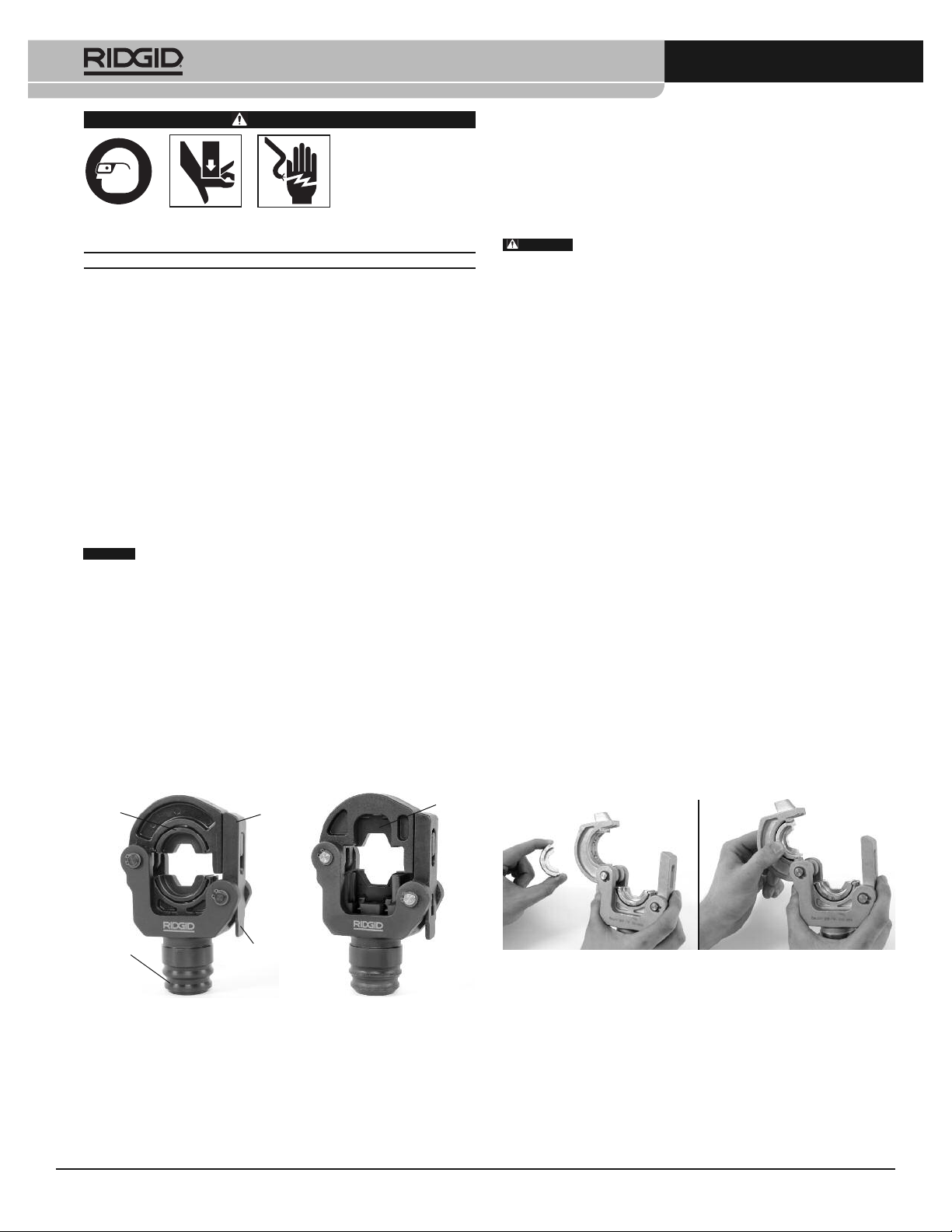
3. Remove battery from electrical tool. Open the Latching Crimp Head
by pressing the latch release. Insert matching dies into the head.
Dies should fit snugly and securely, and the crimping profiles should
align. Do not force dies into head. If there are any issues with die fit,
do not use the tool. Do not operate tool without dies installed.
Do not use with 12 ton or 130 kN dies. This could cause improper
crimp connections.
Figure 2 – Installing Dies in Crimp Head
4. Changing Heads with QCS Coupling – See electrical tool manual.
5. With dry hands install the tool battery.
6. If needed, open the head by pressing the latch release and close
the head around the connector to be crimped. Make sure that the
latch is fully closed – do not operate the tool with the latch open or
partially open.
7. Follow all compression connector manufacturers’ instructions for
crimp location. Some wire sizes may require more than one crimp
per connection.
Center the connector squarely against the crimp profile in the sta-
tionary die. Improper placement can make an incorrect crimp or
damage the equipment.
WARNING
Read and understand
these instru tions, the
ele tri al tool instru -
tions, the instru tions
for the dies to be used,
the instru tions for the
onne tor to be rimped and the warnings and instru tions for all
equipment and material being used before operating this tool to
redu e the risk of serious personal injury.
SAVE THESE INSTRUCTIONS!
•Keep your fingers and hands away from the crimp head during
the crimping cycle. Your fingers or hands can be crushed, fractured
or amputated if they are caught between the dies or the components
and any other object.
•Do not use on energized electrical lines to reduce the risk of elec-
trical shock, severe injury and death. Tool is not insulated Use
appropriate work procedures and personal protective equipment when
working near energized electrical lines.
•Large forces are generated during product use that can reak or
throw parts and cause injury. Stand clear during use and wear ap-
propriate protective equipment, including eye protection.
•Never repair a damaged head. A head that has been welded, ground,
drilled or modified in any manner can break during use. Never replace
individual components. Discard damaged heads to reduce the risk of
injury.
•Use proper tool, die, connector and ca le com ination. Improper
combinations can result in an incomplete or improper crimp which in-
creases the risk of fire, severe injury or death.
Des ription
RIDGID®LR-60B/LS-60B Latching Crimp Head Tools are designed to
crimp electrical compression connectors to their respective wire when
used with appropriate dies.
The tool is available either as an interchangeable head (For RIDGID®
RE 6/RE 60 or Ilsco Electrical Tool) or as part of a dedicated tool (RIDGID®
RE-600 series tools).
Figure 1 – Round Crimp Head Square Crimp Head
(Interchangea le versions)
Spe ifi ation
LR-60B LS-60B
Dies Used ............................Commercially Commercially
Available Round Available Square
60 kN & 6 Ton 60 kN
Conforming to DIN
48083 Type 6M
RIDGID Die Series...............RDD-60, RD -60 SDD-60
LR-60B/LS-60 Latching Crimp Heads Instructions
NOTICE Selection of appropriate materials and joining methods is the
responsibility of the system designer and/or installer. Before any installa-
tion is attempted, careful evaluation of the specific re quire ments should be
completed. Consult connector manufacturer for selection information.
Round
Dies Latch Square
Dies
QCS
Coupling
Latch
Release
WARNING
Printed 2/17
999-999-472.09
EC42593 REV. D
©2015, 2017 RIDGID, Inc.
The Emerson logo and RIDGID logo are registered trademarks of Emerson Electric Co. or RIDGID, Inc. in the U.S. and other countries.
All other trademarks belong to their respective holders.
Test Equipment Depot - 800.517.8431 - 99 Washington Street Melrose, MA 02176 - TestEquipmentDepot.com


