RIDGID R4092 User manual

Cette scie a été conçue et fabriquée conformément aux
strictes normes de fiabilité, simplicité d’emploi et sécurité
d’utilisation. Correctement entretenu, cet outil vous donnera
des années de fonctionnement robuste et sans problème.
AVERTISSEMENT :
Pour réduire les risques de blessures, l’utilisateur
doit lire et veiller à bien comprendre le manuel
d’utilisation avant d’employer ce produit.
Su sierra ha sido diseñado y fabricado de conformidad con
nuestras estrictas normas para brindar fiabilidad, facilidad de
uso y seguridad para el operador. Con el debido cuidado, le
brindarámuchosañosdesólidofuncionamientoysinproblemas.
ADVERTENCIA:
Para reducir el riesgo de lesiones, el usuario debe
leer y comprender el manual del operador antes de
usar este producto.
CONSERVER CE MANUEL POUR
FUTURE RÉFÉRENCE
GUARDE ESTE MANUAL PARA
FUTURAS CONSULTAS
SAVE THIS MANUAL FOR FUTURE REFERENCE
Your saw has been engineered and manufactured to our high standard for dependability, ease of operation, and operator
safety. When properly cared for, it will give you years of rugged, trouble-free performance.
WARNING:
To reduce the risk of injury, the user must read and understand the operator’s manual before using this product.
To register your RIDGID
product, please visit:
http://register.RIDGID.com
Pour enregistrer votre
produit de RIDGID, s’il vous
plaît la visite: http://register.
RIDGID.com
Para registrar su producto
de RIDGID, por favor visita:
http://register.RIDGID.com
OPERATOR’S MANUAL
MANUEL D’UTILISATION
MANUAL DEL OPERADOR
10 in. TILE SAW
SCIE À CARREAUX
DE 254 mm (10 po)
SIERRA DE LOSAS
DE 254 mm (10 pulg.)
R4092

2
Introduction ...................................................................................................................................................................... 2
Introduction / Introducción
General Safety Rules.....................................................................................................................................................3-4
Règles de sécurité générales / Reglas de seguridad generales
Specific Safety Rules........................................................................................................................................................ 5
Règles de sécurité particulières / Reglas de seguridad específicas
Symbols............................................................................................................................................................................ 6
Symboles / Símbolos
Electrical........................................................................................................................................................................7-8
Caractéristiques électriques / Aspectos eléctricos
Features.......................................................................................................................................................................9-10
Caractéristiques / Características
Tools Needed.................................................................................................................................................................. 10
Outils nécessaires / Herramientas necesarias
Loose Parts ...............................................................................................................................................................11-12
Pièces détachées / Piezas sueltas
Assembly...................................................................................................................................................................13-24
Assemblage / Armado
Operation...................................................................................................................................................................25-32
Utilisation / Funcionamiento
Adjustments...............................................................................................................................................................33-36
Réglages / Ajustes
Maintenance..............................................................................................................................................................37-38
Entretien / Mantenimiento
Warranty ......................................................................................................................................................................... 39
Garantie / Garantía
Parts Ordering and Service ...............................................................................................................................Back page
Commande de pièces et réparation / Pedidos de piezas y servicio
INTRODUCTION
INTRODUCTION / INTRODUCCIÓN
This product has many features for making its use more pleasant and enjoyable. Safety, performance, and dependability
have been given top priority in the design of this product making it easy to maintain and operate.
* * *
Ce produit offre de nombreuses fonctions destinées à rendre son utilisation plus plaisante et satisfaisante. Lors de la
conception de ce produit, l’accent a été mis sur la sécurité, les performances et la fiabilité, afin d’en faire un outil facile à
utiliser et à entretenir.
* * *
Este producto ofrece numerosas características para hacer más agradable y placentero su uso. En el diseño de este producto
se ha conferido prioridad a la seguridad, el desempeño y la fiabilidad, por lo cual se facilita su manejo y mantenimiento.
TABLE OF CONTENTS
TABLE DES MATIÈRES / ÌNDICE DE CONTENIDO

3 — English
GENERAL SAFETY RULES
WARNING:
Read and understand all instructions. Failure to
follow all instructions listed below, may result in
electric shock, fire and/or serious personal injury.
READ ALL INSTRUCTIONS
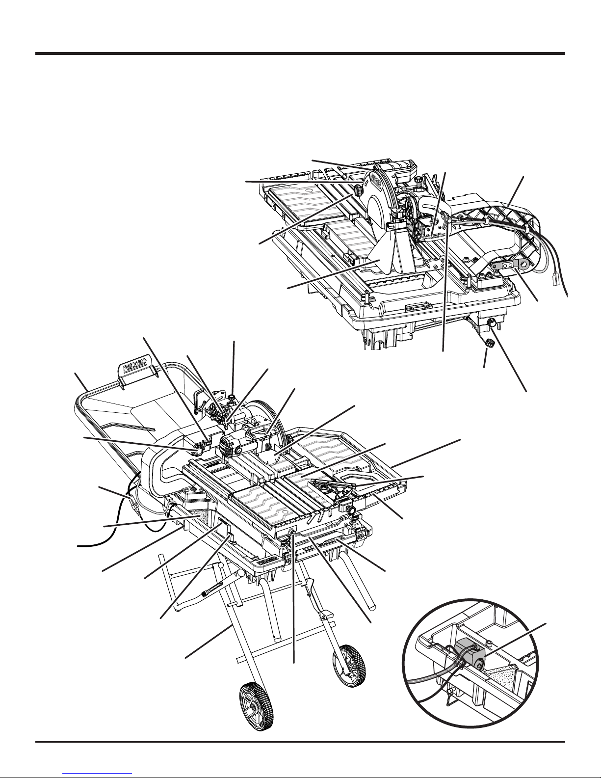
KNOWYOURPOWERTOOL.Readthe operator’smanual
carefully. Learn the saw’s applications and limitations as
well as the specific potential hazards related to this tool.
GUARD AGAINST ELECTRICAL SHOCK BY
PREVENTING BODY CONTACT WITH GROUNDED
SURFACES. For example, pipes, radiators, ranges,
refrigerator enclosures.
KEEP GUARDS IN PLACE and in good working order.
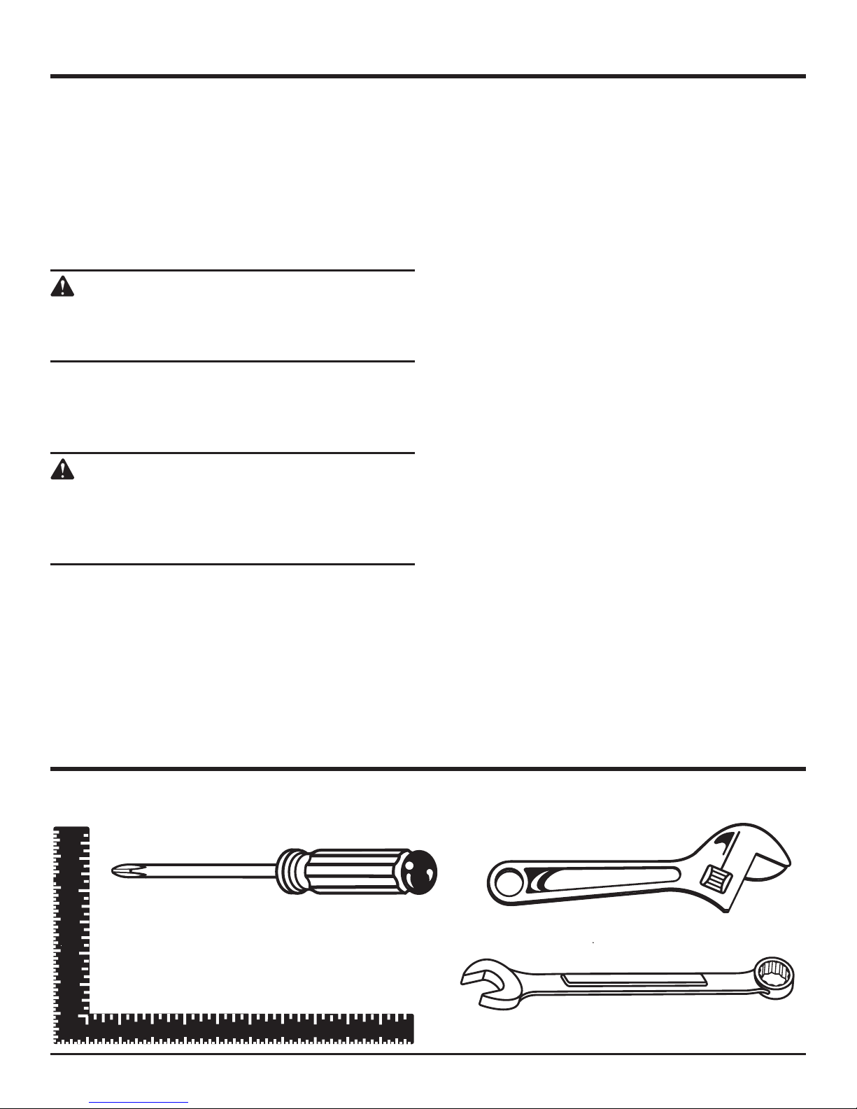
REMOVE ADJUSTING KEYS AND WRENCHES. Form
habit of checking to see that keys and adjusting wrenches
are removed from tool before turning it on.
KEEPWORKAREACLEAN.Clutteredareasandbenches
invite accidents. DO NOT leave tools or pieces of tile on
the saw while it is in operation.
DO NOT USE IN DANGEROUS ENVIRONMENTS. Do
not use power tools in damp or wet locations or expose
to rain. Keep the work area well lit.
KEEP CHILDREN AND VISITORS AWAY. All visitors
should wear safety glasses and be kept a safe distance
fromwork area.Donotletvisitorscontacttoolorextension
cord while operating.
MAKE WORKSHOP CHILDPROOF with padlocks and
master switches, or by removing starter keys.
DON’T FORCE TOOL. It will do the job better and safer
at the feed rate for which it was designed.
USE RIGHT TOOL. Don’t force the tool or attachment to
do a job it was not designed for. Don’t use it for a purpose
not intended.
USE THE PROPER EXTENSION CORD. Make sure
your extension cord is in good condition. Use only a
cord heavy enough to carry the current your product
will draw. An undersized cord will cause a drop in line
voltage resulting in loss of power and overheating. A wire
gauge size (A.W.G.) of at least 14 is recommended for an
extension cord 25 feet or less in length. If in doubt, use
the next heavier gauge. The smaller the gauge number,
the heavier the cord.
DRESS PROPERLY. Do not wear loose clothing, gloves,
neckties, or jewelry. They can get caught and draw you
into moving parts. Rubber gloves and nonskid footwear
(rubber soled boots) are recommended when working
outdoors. Also wear protective hair covering to contain
long hair.
ALWAYS WEAR EYE PROTECTION WITH SIDE
SHIELDSWHICHIS MARKED TO COMPLY WITH ANSI
Z87.1 WHEN USING THIS PRODUCT.
SECURE WORK. Use clamps or a vise to hold work when
practical, it is safer than using your hand and frees both
hands to operate the tool.
DON’T OVERREACH. Keep proper footing and balance
at all times.
MAINTAIN TOOLS WITH CARE. Keep tools sharp and
cleanforbetterandsaferperformance.Followinstructions
for lubricating and changing accessories.
DISCONNECTTOOLS.When not in use, beforeservicing,
orwhen changing attachments, wheels, bits, cutters, etc.,
all tools should be disconnected.
AVOID ACCIDENTAL STARTING. Be sure switch is off
when plugging in any tool.
USE RECOMMENDED ACCESSORIES. Consult the
operator’s manual for recommended accessories. The
use of improper accessories may risk injury.
NEVER STAND ON TOOL. Serious injury could occur if
the tool is tipped or if the cutting tool is unintentionally
contacted.
CHECK DAMAGED PARTS. Before further use of the
tool, a guard or other part that is damaged should be
carefullychecked todetermine that it will operate properly
and perform its intended function. Check for alignment
of moving parts, binding of moving parts, breakage of
parts, mounting and any other conditions that may affect
its operation. A guard or other part that is damaged must
be properly repaired or replaced by an authorized service
center to avoid risk of personal injury.
USE THE RIGHT DIRECTION OF FEED. Feed work into
a wheel or cutter against the direction of rotation of wheel
or cutter only.
NEVER LEAVE TOOL RUNNING UNATTENDED. TURN
THE POWER OFF. Don’t leave tool until it comes to a
complete stop.
PROTECT YOUR LUNGS. Wear a face or dust mask if
the cutting operation is dusty.
PROTECT YOUR HEARING. Wear hearing protection
during extended periods of operation.
DO NOT ABUSE CORD. Never yank cord to disconnect
from receptacle. Keep cord away from heat, oil, and sharp
edges.
ALWAYS USE AN OUTDOOR EXTENSION CORD
MARKED “W-A” OR “W”. These cords are rated for
outdoor use and reduce the risk of electric shock.
ALWAYS KEEP THE WHEEL GUARD IN PLACE and in
working order.

4 — English
GENERAL SAFETY RULES
KEEP HANDS AWAY FROM CUTTING AREA. Keep
hands away from wheels. Do not reach underneathwork
or around or over the wheel while wheel is rotating. Do not
attempt to remove cut material when wheel is moving.
WHEEL COASTS AFTER BEING TURNED OFF.
NEVERUSE IN AN EXPLOSIVE ATMOSPHERE. Normal
sparking of the motor could ignite fumes.
INSPECT TOOL CORDS PERIODICALLY. If damaged,
have repaired by a qualified service technician at an
authorized service facility. The conductor with insulation
havingan outer surface that is greenwith or without yellow
stripes is the equipment-grounding conductor. If repair
or replacement of the electric cord or plug is necessary,
do not connect the equipment-grounding conductor to a
live terminal. Repair or replace a damaged or worn cord
immediately. Stay constantly aware of cord location and
keep it well away from the rotating wheel.
INSPECT EXTENSION CORDS PERIODICALLY and
replace if damaged.
GROUND ALL TOOLS. If tool is equipped with three-
prong plug,it should be plugged intoa three-hole electrical
receptacle.
ONLY POWER THE TOOL WITH A GFCI (GROUND
FAULT CIRCUIT INTERRUPTOR) PROTECTED
OUTLET.
CHECK WITH A QUALIFIED ELECTRICIAN or service
personnel if the grounding instructions are not completely
understood or if in doubt as to whether the tool is properly
grounded.
USE ONLY CORRECT ELECTRICAL DEVICES:3-wire
extension cords that have 3-prong grounding plugs and
3-pole receptacles that accept the tool’s plug.
DO NOT MODIFY the plug provided. If it will not fit the
outlet, have the proper outlet installed by a qualified
electrician.
KEEP TOOL DRY, CLEAN, AND FREE FROM OIL AND
GREASE. Always use a clean cloth when cleaning. Never
use brake fluids, gasoline, petroleum-based products, or
any solvents to clean tool.
STAY ALERT AND EXERCISE CONTROL. Watch what
you are doing and use common sense. Do not operate
tool when you are tired. Do not rush.
DO NOT USE TOOL IF SWITCH DOES NOT TURN IT
ON AND OFF. Have defective switches replaced by an
authorized service center.
USEONLYCORRECTWHEELS.Do not use wheels with
incorrect size holes. Never use washers or arbor nuts that
are defective or incorrect. The maximum wheel capacity
of your saw is 10 in. (254 mm).
BEFORE MAKING A CUT, BE SURE ALL
ADJUSTMENTS ARE SECURE.
NEVER TOUCH WHEEL or other moving parts during
use.
NEVER START A TOOL WHEN ANY ROTATING
COMPONENTISIN CONTACTWITHTHEWORKPIECE.
DO NOT OPERATE A TOOL WHILE UNDER THE
INFLUENCE OF DRUGS, ALCOHOL, OR ANY
MEDICATION.
WHEN SERVICING use only identical replacement parts.
Use of any other parts may create a hazard or cause
product damage.
USE ONLY RECOMMENDED ACCESSORIES listed in
thismanualoraddendums.Useofaccessories that arenot
listedmaycause the risk of personal injury. Instructions for
safe use of accessories are included with the accessory.
DOUBLE CHECK ALL SETUPS. Make sure wheel is tight
and not making contact with saw or workpiece before
connecting to power supply.

5 — English
SECURE WORK firmly against the miter guide or fence.
NEVER stand or have any part of your body in line with
the path of the wheel.
NEVERattempt to freeastalledwheel without first turning
the saw OFF and disconnecting the saw from the power
source.
IF THE POWER SUPPLY CORD IS DAMAGED, it must
be replaced only by the manufacturer or by an authorized
service center to avoid risk.
AVOID AWKWARD OPERATIONS AND HAND
POSITIONS where a sudden slip could cause your hand
to move into the cutting tool.
MAKE SURE THE WORK AREA HAS AMPLE
LIGHTING to see the work and that no obstructions will
interfere with safe operation BEFORE performing any
work using the saw.
ALWAYS TURN OFF SAW before disconnecting it, to
avoid accidental starting when reconnecting to power
supply.
THIS TOOL should have the following markings:
a) To reduce the risk of injury, the user must read and
understand operator’s manual.
b) Wear eye, hearing, and respiratory protection when
operating the tool.
c) Do not remove the wheel guard.
d) Do not stack or store tiles on water trays.
e) Never operate the tool without the wheel guard
securely closed.
f) Turn off tool, wait for the wheel to stop moving, and
disconnect the power to the tool before servicing,
when changing cutting wheels, or cleaning.
g) Never use wheels that have openings, grooves, or
teeth on this tool.
h) Alwaysinspect and replacedamagedcuttingwheels
before operating the tool.
i) Do not expose to rain or other damp locations.
j) Do not fill water bath above maximum water fill line.
SAVE THESE INSTRUCTIONS. Refertothemfrequently
and use to instruct other users. If you loan someone
this tool, loan them these instructions too.
SPECIFIC SAFETY RULES
CALIFORNIA PROPOSITION 65
WARNING:
This product and some dust created by power sanding, sawing, grinding, drilling, and other construction activities
may contain chemicals, including lead, known to the State of California to cause cancer, birth defects, or other
reproductive harm. Wash hands after handling.
Some examples of these chemicals are:
• lead from lead-based paints,
• crystalline silica from bricks and cement and other masonry products and,
• arsenic and chromium from chemically-treated lumber.
Your risk from exposure to these chemicals varies, depending on how often you do this type of work. To reduce
your exposure, work in a well-ventilated area and with approved safety equipment, such as dust masks that are
specially designed to filter out microscopic particles.

6 — English
SYMBOLS
The following signal words and meanings are intended to explain the levels of risk associated with this product.
SYMBOL SIGNAL MEANING
DANGER: Indicates an imminently hazardous situation, which, if not avoided, will result
in death or serious injury.
WARNING: Indicates a potentially hazardous situation, which, if not avoided, could result
in death or serious injury.
CAUTION: Indicates a potentially hazardous situation, which, if not avoided, may result in
minor or moderate injury.
NOTICE: (Without Safety Alert Symbol) Indicates important information not related to an
injury hazard, such as a situation that may result in property damage.
Some of the following symbols may be used on this product. Please study them and learn their meaning. Proper
interpretation of these symbols will allow you to operate the product better and safer.
SYMBOL NAME DESIGNATION/EXPLANATION
Safety Alert Indicates a potential personal injury hazard.
Read Operator’s
Manual
To reduce the risk of injury, user must read and understand operator’s
manual before using this product.
Eye, Ear, & Breathing
Protection
Always wear eye protection with side shields marked to comply with
ANSI Z87.1 along with hearing and breathing protection.
Wet Conditions Alert Do not expose to rain or use in damp locations.
No Hands Failure to keep your hands away from the wheel will result in
serious personal injury.
Electrocution Failure to properly ground can result in electrocution.
V Volts Voltage
A Amperes Current
Hz Hertz Frequency (cycles per second)
min Minutes Time
Alternating Current Type of current
n
o
No-Load Speed Rotational speed, at no load
.../min Per Minute Revolutions, strokes, surface speed, orbits etc., per minute

7 — English
ELECTRICAL
ELECTRICAL CONNECTION
This tool is powered by a precision built electric motor. It
should be connected to a power supply that is 120 V, AC
only (normal household current), 60 Hz. Do not operate
this tool on direct current (DC). A substantial voltage drop
will cause a loss of power and the motor will overheat. If the
saw does not operate when plugged into an outlet, double
check the power supply.
SPEED AND WIRING
The no-load speed of this tool is approximately 4,000 rpm.
This speed is not constant and decreases under a load or
with lower voltage. For voltage, the wiring in a shop is as
important as the motor’s horsepower rating. A line intended
only for lights cannot properly carry a power tool motor. Wire
that is heavy enough for a short distance will be too light for
a greater distance. A line that can support one power tool
may not be able to support two or three tools.
GROUNDING INSTRUCTIONS
See Figure 1.
This tool must be grounded. In the event of a malfunction or
breakdown, grounding provides a path of least resistance
for electric current to reduce the risk of electric shock. This
tool is equipped with an electric cord having an equipment
grounding conductor and a grounding plug. The plug must be
plugged into a matching outlet that is properly installed and
grounded in accordance with all local codes and ordinances.
Do not modify the plug provided. If it will not fit the outlet,
have the proper outlet installed by a qualified electrician.
WARNING:
Improper installation of the grounding plug can
result in a risk of electric shock. When repair or
replacement of the cord is required, do not connect
the grounding wire to either flat blade terminal.
The wire with insulation having an outer surface
that is green with or without yellow stripes is the
grounding wire.
Check with a qualified electrician or service personnel if the
grounding instructions are not completely understood, or if
in doubt as to whether the tool is properly grounded.
Repair or replace a damaged or worn cord immediately.
This product is for use on a nominal 120 volt circuit and has
a grounding plug similar to the plug illustrated in figure 1.
Only connect the product to an outlet having the same
configuration as the plug. Do not use an adapter with this
product.
Ground Fault Circuit Interrupter (GFCI) protection should be
provided on the circuit(s) or outlet(s) to be used for the tile
saw. Outlets are available having built-in GFCI protection
and may be used for this measure of safety.
EXTENSION CORDS
Use only 3-wire extension cords that have 3-prong grounding
plugs and 3-pole receptacles that accept the tool’s plug.
When using a power tool at a considerable distance from
the power source, use an extension cord heavy enough
to carry the current that the tool will draw. An undersized
extension cord will cause a drop in line voltage, resulting in
a loss of power and causing the motor to overheat. Use the
chart provided below to determine the minimum wire size
required in an extension cord. Only round jacketed cords
listed by Underwriter’s Laboratories (UL) should be used.
**Ampere rating (on tool data plate)
0-2.0 2.1-3.4 3.5-5.0 5.1-7.0 7.1-12.0 12.1-16.0
Cord Length Wire Size (A.W.G.)
25'16 16 16 16 14 14
50'16 16 16 14 14 12
100'16 16 14 12 10 —
**Used on 12 gauge - 20 amp circuit.
NOTE: AWG = American Wire Gauge
Always use an extension cord that is designed for outside
use. This is indicated by the letters “W-A” or “W” on the
cord’s jacket.
Before using an extension cord, inspect it for loose or
exposed wires and cut or worn insulation.
Use only extension cords that are intended for outdoor
use. These extension cords are identified by a marking
“Acceptable for use with outdoor appliances; store indoors
while not in use”. Use only extension cords having an
electrical rating not less than the rating of the product. Do
not use damaged extension cords. Examine extension cord
before using and replace if damaged. Do not abuse extension
cords and do not yank on any cord to disconnect. Keep cord
away from heat and sharp edges. Always disconnect the
extension cord from the receptacle before disconnecting
the product from the extension cord.
WARNING:
Keep the extension cord clear of the working area.
Position the cord so that it will not get caught on
lumber, tools or other obstructions while you are
working with a power tool. Failure to do so can
result in serious personal injury.
WARNING:
Check extension cords before each use. If
damaged replace immediately. Never use tool with
a damaged cord since touching the damaged area
could cause electrical shock resulting in serious
injury.

8 — English
ELECTRICAL
If the saw is used with an extension cord, ensure the
connection of the tool’s power cord and the extension cord
are not on the ground.
If a protected outlet is not available, do not use the saw
until an outlet can be changed or auxiliary protection can
be obtained. These auxiliary protection devices are available
at your local retailer.
POSITION OF THE TILE SAW
See Figures 2 and 3.
To avoid the possibility of the tool plug or outlet getting
wet, position tile saw to one side of a wall-mounted outlet
to prevent water from dripping onto the outlet or plug. The
operator should arrange a “drip loop” in the cord connecting
the saw to the outlet. The “drip loop” is that part of the cord
below the level of the outlet, or the connector if an extension
cord is used, to prevent water traveling along the cord and
coming in contact with the outlet.
If the plug or outlet does get wet, DO NOT unplug the cord.
Disconnect the fuse or circuit breaker that supplies power
to the tool then unplug and examine for the presence of
water in the outlet.
WARNING:
To reduce the risk of electrocution, keep all
connections dry and off the ground. Do not touch
the plug with wet hands.
Fig. 1
GROUNDING
PIN
GROUND FAULT
OUTLET
POWER
CORD
DRIP LOOP
Fig. 3
Fig. 2
EXTENSION
CORD

9 — English
PRODUCT SPECIFICATIONS
Wheel Diameter..........................................................10 in.
Wheel Arbor.............................................................. 5/8 in.
Throat Capacity..........................................................17 in.
Rip Capacity (tile size) ................................................34 in.
Diagonal Capacity (tile size) .......................................24 in.
Maximum Depth of Cut .........................................3-1/2 in.
Rating ...........................................120 V~, 15 Amps, 60 Hz
No-Load Speed.....................................4,000 r/min. (RPM)
FEATURES
Fig. 4
WSUV™
STAND
WHEEL
WRENCH
STORAGE
HEX KEY
STORAGE
WHEEL GUARD
LOCK
WHEEL GUARD
MICRO-CUT
FENCE SUPPORT
LOCK PIN
“D” HANDLE
SAW ARM
PUMP SWITCH
WATER TRAY
EXTENSION
(REAR)
WATER TRAY
EXTENSION
(SIDE)
MOTOR HEAD
LOCK KNOB
ON/OFF
SWITCH
DEPTH STOP
LOCK KNOB
DRAINAGE
DRAIN
CAP
CUTTING
WHEEL
MITER
GUIDE
MAX WATER
FILL LINE
WATER
TRAY
SLIDING
TABLE
MIN WATER
FILL LINE
WATER
FILTER
BEVEL LOCK
KNOB
PUMP
OUTLET
GREASE
PENCIL
STORAGE
SPLASH
GUARD
LASER SWITCH
TABLE
LOCK
KNOB
FRAME
WATER
PUMP

10 — English
FEATURES
KNOW YOUR TILE SAW
See Figure 4.
The safe use of this product requires an understanding of
the information on the tool and in this operator’s manual as
well as a knowledge of the project you are attempting. Before
use of this product, familiarize yourself with all operating
features and safety rules.
10 in. TILE CUTTING WHEEL - A 10 in. tile cutting wheel
is included with your saw.
WARNING:
Do not use wheels rated less than the speed of
this tool. Failure to heed this warning could result
in personal injury.
BEVEL LOCK KNOB - The bevel lock knob securely locks
the saw head at any bevel angle between 0º and 45º. It is
recommended that you only make bevel cuts at 0˚, 22.5˚,
and 45˚ angles.
WARNING:
Making bevel cuts at angles other than 0˚, 22.5˚,
and 45˚ angles could cause the cutting wheel to
come in contact with the sliding table resulting in
damage to the unit and/or possible serious injury.
ADJUSTABLE LASER ALIGNMENT SYSTEM - For more
accurate cuts, a laser guide is included with the tile saw.
When used properly, the laser guide makes accurate,
precision cutting simple and easy. Simply push the button
to turn the laser on or off.
ELECTRIC BRAKE - An electric brake has been provided
to quickly stop wheel rotation after the saw is turned off.
MICRO-CUT FENCE SUPPORT - This machined ledge
helps prevent tile from cracking.
MITER GUIDE - The easy-to-read indicator on the miter
guide shows the exact angle for a miter cut with detents at
0°, 22.5°, and 45°.
ON/OFF SWITCH - This saw has an easy access power
switch located on the saw arm. To lock the switch, install a
padlock (not included) through the hole in the switch. When
the lock is installed and locked, the switch is inoperable.
Store the padlock key in another location.
SLIDING TABLE - The sliding table allows the user to slide
the workpiece into the cutting wheel for accurate cuts.
SPLASH GUARD ASSEMBLY WITH TOOLESS
REMOVABLE SIDE GUARD - The splash guard helps
contain spray and mist.
WATER PUMP - The water pump provides water to the
cutting wheel.
WATER TRAY EXTENSIONS - When cutting larger tile, the
extensions keeps work area cleaner and drier.
WRENCH STORAGE - The saw has a convenient storage
area specifically designed for the wheel wrench (back of
the saw arm) and the hex key (below the bevel lock knob).
WSUV™(WET SAW UTILITY VEHICLE) STAND - Attached
to the saw base, the stand opens and closes with ease
making transportation simple.
TOOLS NEEDED
The following tools (not included or drawn to scale) are needed for assembly and alignment:
ADJUSTABLE WRENCH
10 mm, 13 mm and 17 mm
WRENCH
FRAMING SQUARE
Fig. 5
PHILLIPS SCREWDRIVER

11 — English
LOOSE PARTS
The following items are included with your tile saw:
Fig. 6
A - Left Outer Tube............................................................ 1
B - Right Outer Tube.......................................................... 1
C - Lower Brace ................................................................ 1
D - Inner Leg Assembly ..................................................... 1
E - Left Upper Tube........................................................... 1
F - Right Upper Tube......................................................... 1
G - Nut ............................................................................. 10
H - Washer (Small)............................................................. 2
I - Wheel........................................................................... 2
J - Spacer (Large) ............................................................. 2
K - Carriage Bolt................................................................ 8
L - Spacer (Small)............................................................ 16
M- Hex Bolt....................................................................... 2
N - Center Brace................................................................ 1
O - Washer (Large)............................................................. 2
A
B
N
D
E
F
C
GH
K
M
L
J
IO
G

12 — English
LOOSE PARTS
The following items are included with your tile saw: A
Fig. 7
A - Motor head assembly...............................................1
B - Tile cutting wheel......................................................1
C - Rear splash guard ....................................................1
D - Side splash guard.....................................................1
E - Wheel wrench...........................................................1
F - Hex Key (8 mm and 5 mm).......................................1
G - Cap screw ................................................................4
H - Washer (Medium)......................................................4
I - Base .........................................................................1
J - Frame and sliding table ............................................1
K - Sliding table extension .............................................1
L - Rear water tray extension.........................................1
M- Side water tray extension.........................................1
N - Miter guide ...............................................................1
O - Water tray .................................................................1
P - Water filter ................................................................1
Q - Water pump..............................................................1
R - Hitch pin ...................................................................4
BC
D
E
F
G
H
J
N
M
O
L
I
Q
P
R
K

13 — English
ASSEMBLY
UNPACKING
See Figures 6 and 7.
This product requires assembly.
Carefully lift the parts from the carton and place on a level
work surface.
NOTE: The side water tray extension is located beneath
the polyfoam.
WARNING:
Do not use this product if any parts on the Loose
Parts List are already assembled to your product
when you unpack it. Parts on this list are not
assembled to the product by the manufacturer and
require customer installation. Use of a product that
may have been improperly assembled could result
in serious personal injury.
Inspect the tool carefully to make sure no breakage or
damage occurred during shipping.
Donotdiscardthe packing material until you have carefully
inspected and satisfactorily operated the tool.
The saw is factory set for accurate cutting. After
assembling it, check for accuracy. If shipping has
influenced the settings, refer to specific procedures
explained in this manual.
If any parts are damaged or missing, please call
1-866-539-1710 for assistance.
WARNING:
If any parts are damaged or missing do not operate
this tool until the parts are replaced. Use of this
product with damaged or missing parts could
result in serious personal injury.
WARNING:
Do not attempt to modify this tool or create
accessories not recommended for use with this
tool. Any such alteration or modification is misuse
and could result in a hazardous condition leading
to possible serious personal injury.
WARNING:
Do not connect to power supply until assembly is
complete. Failure to comply could result in
accidental starting and possible serious personal
injury.
INSTALLING MOTOR HEAD ASSEMBLY TO
BASE
See Figure 8.
Align the holes in the motor head assembly with the holes
on the base.
NOTE: The studs in the motor head assembly should be
in line with the center holes in the base.
Lower the motor head assembly onto the base and push
the studs into the center holes.
Thread cap screws through washers and motor head
assembly and into holes on base.
Tighten screws using the 8 mm hex key (provided).
NOTE: Hex key storage is located on the back of the saw
arm.
Set motor head and base assembly aside.
Fig. 8
MOTOR HEAD
ASSEMBLY
HOLES
BASE
CAP
SCREWS
WASHERS
STUDS

14 — English
ASSEMBLY
ASSEMBLING WSUV™STAND
See Figures 9 - 15.
Many of the WSUV™stand parts are movable. All hardware
must be tightened securely but not so tight that the WSUV™
stand won’t open and close. For easier assembly, match
letter to letter and finger-tighten all fasteners. Only tighten
fasteners securely when you are sure the release lever locks
over the stop pin.
Place the center brace on top of the inner leg assembly
(curve side up) with the stop pin under the release lever.
NOTE: The stop pins rest on top of inner leg assembly.
Insert carriage bolt through the top hole of the inner leg
assembly, two small spacers, and the lower hole of the
center brace. Secure with nut and repeat for the other
side.
Position the inner leg assembly and left outer tube so that
they resemble an “X”.
Insert carriage bolt through the center hole of the left
outer tube, two small spacers, and the lower hole of the
inner leg assembly. Secure with nut.
Position the inner leg assembly and right outer tube so
that they resemble an “X”.
Insert carriage bolt through the center hole of the right
outer tube, two small spacers, and the lower hole of the
inner leg assembly. Secure with nut.
LEFT
OUTER TUBE
LETTERS
NUT
INNER LEG
ASSEMBLY
INNER LEG
ASSEMBLY
Fig. 10
Fig. 9
Fig. 11
CENTER
BRACE
STOP
PIN
RELEASE
LEVER
CARRIAGE
BOLT
CARRIAGE
BOLT
SMALL
SPACERS
SMALL
SPACERS
NUT

15 — English
ASSEMBLY
NUT
LEFT
UPPER TUBE
RIGHT
UPPER TUBE
TAB
INNER LEG
ASSEMBLY
CENTER
BRACE
Fig. 13
Fig. 15
Fig. 14
CARRIAGE
BOLT
SMALL
SPACERS
Place a large spacer over the end of the lower brace.
Insert a hex bolt through the bottom of the right outer
tube, the large spacer, and into the lower brace. Tighten
securely. Repeat for the other side.
With the curved ends turned downward, secure the upper
tubes to the WSUV™stand using carriage bolts, small
spacers, and nuts.
NOTE: The upper tube with the tab should be installed
on the right.
NUT
WHEEL
AXLE
SMALL
WASHER
LARGE
WASHER
LEFT
OUTER TUBE
LOWER
BRACE
RIGHT
OUTER TUBE
Fig. 12
LARGE
SPACER
HEX
BOLT
Slide a large washer, wheel, and small washer onto an
axle. Secure in place using nut. Repeat with the second
wheel.

16 — English
ASSEMBLY
ATTACHING WATER TRAY TO WSUV™STAND
See Figure 16.
Open the WSUV™stand as described on page 23.
Place the water tray on the WSUV™stand. Align the holes
in the water tray with the holes in the WSUV™stand’s
handles.
NOTE: The portion of the water tray with the Ridgid logo
should be on the wheel side of the stand.
Secure the water tray to the stand using four hitch pins.
INSTALLING WATER FILTER AND WATER
PUMP
See Figures 17 - 19.
The water pump recirculates water from the tray to the
cutting wheel.
Locate filter slots and pump well in water tray. Pump well
is marked, “PUMP”.
Slide filter into filter slots, as shown.
Locate the “Max/Min” water flow selector on the pump.
For best performance, start with the flow to “Max” to
control the flow of water over the wheel.
NOTE: Water flow can be adjusted during use by
removing the filter, reaching into water well and turning
flow selector on pump. Reinsert filter.
Place water pump into pump well.
Fig. 16
WSUV™STAND
WATER TRAY
HITCH PIN
Fig. 17
Fig. 18
WATER
FILTER
WATER TRAY
FILTER SLOTS
PUMP WELL
POWER
CORD
NOTCH
Fig. 19
WATER
FLOW
SELECTOR
MAXIMUM
FLOW
MINIMUM
FLOW
WATER PUMP
POWER CORD
WATER
HOSE
NOTCH
PUMP
WELL

17 — English
WATER
TRAY
MOTOR HEAD
AND BASE
ASSEMBLY
Fig. 20
INSTALLING MOTOR HEAD AND BASE TO
WATER TRAY
See Figure 20.
Attach the water hose to the pump elbow.
Rest pump power cord and water hose in the notches
provided on the water tray.
Carefully lift the motor head and base assembly over the
water tray, as shown.
LATCHES
HEAVY DUTY
TAB
BAR SLOT
RUBBER
BOOT
PUMP
POWER
CORD
Tilt the base and insert heavy duty tab into the bar slot
on water tray.
Secure the base in place with latches on front of the water
tray.
Connect the pump power cord to the motor head power
cord. Check that the rubber boot is pulled over cord
connection to help keep water off the plug.
PUMP ELBOW
WATER HOSE
ASSEMBLY
HEAVY
DUTY TAB
BAR
SLOT

18 — English
INSTALLING/REMOVING THE FRAME AND
SLIDING TABLE
See Figures 21 - 23.
Pull the frame lock lever out and turn 90˚ counterclockwise
to the “unlocked position”.
Release the lever.
Grasp the sliding table firmly and guide the table and
frame onto the rails of the base.
Holding the table and frame parallel with the base, push
the table and frame toward the back of the saw.
ASSEMBLY
Fig. 21
SAW
FRONT SLIDING
TABLE AND
FRAME
SLIDING
TABLE
SLIDING
TABLE
NOTE: The table and frame should move smoothly over
the rollers inside the rails.
To lock the frame:
Pull the frame lock lever out and turn 90˚ clockwise to
the “locked position”.
Release the lever.
NOTE: When the sliding table and frame are installed,
and you push the frame, it will “click” into place. This
is the frame lock lever snapping into a hole in the frame
locking it in place.
To unlock the frame:
Pull the frame lock lever out and turn 90˚ clockwise to
the “unlocked position”.
To lock/unlock the sliding table:
Lock the frame.
Pull the table lock knob out and up to unlock the sliding
table.
To lock the sliding table, move the table to the front of
the frame until the table lock knob snaps into place.
To remove the frame and sliding table:
Lock the sliding table.
Pull and hold the frame lock lever out.
Move the sliding table and frame to the front of the saw
and remove.
Fig. 22
SLIDING TABLE
AND FRAME IN
LOCKED POSITION
FRAME LOCK
LEVER
UNLOCK LOCK
FRAME LOCK
LEVER
Fig. 23
TABLE
LOCK
KNOB
FRAME
LOCK
UNLOCK
FRAME

19 — English
ASSEMBLY
TILE CUTTING WHEEL
For maximum performance and safety, it is recommended
that you use the 10 in. cutting wheel provided with your
saw. Additional cutting wheels of the same high quality are
available at your local dealer.
WARNING:
Do not use cutting wheels rated less than the no-
load speed of this tool. Failure to heed this warning
could result in personal injury. Do not use wheel
with cracks, gaps, or teeth.
WARNING:
To prevent possible electrical hazards, have a
qualified electrician check the line if you are not
certain that it is properly wired.
INSTALLING THE CUTTING WHEEL
See Figures 24 and 25.
WARNING:
A 10 in. tile cutting wheel is the maximum wheel
capacity of the saw. Never use a wheel that is too
thick to allow wheel washer to engage with the
flats on the spindle. Larger wheels will come in
contact with the wheel guard, while thicker wheels
will prevent the wheel nut from securing the wheel
on the spindle. Either of these situations could
result in a serious accident and can cause serious
personal injury.
Unplug the saw.
Move the sliding table and frame to the front of the saw.
SPINDLE
LOCK
WHEEL
GUARD LOCK
WHEEL
WRENCH Fig. 24
TO
TIGHTEN
TO
LOOSEN
Loosen wheel guard lock by turning counterclockwise
and open the cutting wheel guard.
Depress and hold the spindle lock.
Using the wheel wrench provided, remove the wheel nut.
Release the spindle lock button.

20 — English
ASSEMBLY
Remove the outer washer.
Slide the cutting wheel onto spindle.
NOTE: Two water nozzles come installed on this product. Be
sure to install cutting wheel so that there is a water nozzle on
each side of cutting wheel with water ports facing the cutting
wheel. The outer water nozzle can be easily removed for
installation of cutting wheel. Check that outer nozzle outlet
hole has been reattached with water port facing toward the
cutting wheel.
WARNING:
If the inner washer has been removed, replace
it before placing wheel on spindle. Failure to do
so could cause an accident since the wheel will
not tighten properly. Never use wheels that have
openings, grooves, or teeth on this tool.
Wipe a drop of oil onto the washer where it contacts the
cutting wheel.
Place an outer washer onto the spindle. The double “D”
flats on the washer align with the flats on the spindle. Be
sure the hollow side of the washer is against the cutting
wheel.
Place wheel nut on spindle.
Depress the spindle lock button and rotate the cutting
wheel until the spindle locks.
Using the wheel wrench provided, tighten nut securely.
Release the spindle lock button.
Close and lock the wheel guard.
Fig. 25
INNER
WASHER
SPINDLE
WATER
NOZZLES
OUTER
WASHER
WHEEL
NUT
INSTALLING SPLASH GUARD ASSEMBLY
See Figures 26 - 28.
The splash guard on this saw is a two-part assembly.
Attaching rear splash guard:
Remove screw and washer from the back of the motor
head.
Line up rear splash guard holes with screw hole and post
on back of cutting wheel guard, as shown.
Insert screw through washer and splash guard then thread
into screw hole.
Tighten securely. Be careful not to overtighten.
Fig. 26
SCREW HOLE
POST REAR SPLASH
GUARD
WASHER
SCREW
Table of contents
Languages:
Other RIDGID Saw manuals

RIDGID
RIDGID R4110 User manual

RIDGID
RIDGID R8642VN User manual

RIDGID
RIDGID R8452 User manual

RIDGID
RIDGID R3002 User manual

RIDGID
RIDGID 5228 User manual

RIDGID
RIDGID 1224-A Owner's manual

RIDGID
RIDGID AC9944 User manual

RIDGID
RIDGID R4514 User manual

RIDGID
RIDGID BS1400 User manual

RIDGID
RIDGID R4093 User manual

RIDGID
RIDGID BS1400 User manual

RIDGID
RIDGID R3210-1 User manual

RIDGID
RIDGID R8658 User manual

RIDGID
RIDGID R3205 User manual

RIDGID
RIDGID R3000 User manual

RIDGID
RIDGID R4141 User manual

RIDGID
RIDGID R3031 User manual

RIDGID
RIDGID BS14002 User manual

RIDGID
RIDGID R41222 User manual

RIDGID
RIDGID R4091 User manual