F10 - I
PARTS LIST
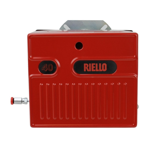
Your Riello 40 F10 burner should include the following parts. Please check to make
sure all parts are present before beginning the installation.
*OEM burners shipped with combustion head mounted.
TABLE OF CONTENTS
TECHNICAL DATA. . . . . . . . . . . . . . . . . . . . . . . . . . . . . . . . . . . . . . . . . . . 1
Dimensions. . . . . . . . . . . . . . . . . . . . . . . . . . . . . . . . . . . . . . . . . . . 1
Specifications . . . . . . . . . . . . . . . . . . . . . . . . . . . . . . . . . . . . . . . . . 1
OIL BURNER COMPONENTS IDENTIFICATION . . . . . . . . . . . . . . . . . . . . 2
F10 Burner Components . . . . . . . . . . . . . . . . . . . . . . . . . . . . . . . . . 2
Serial Number Identification . . . . . . . . . . . . . . . . . . . . . . . . . . . . . . 2
INITIAL SET-UP . . . . . . . . . . . . . . . . . . . . . . . . . . . . . . . . . . . . . . . . . . . . . 2
ASSEMBLY OF AIR TUBE TO BURNER CHASSIS. . . . . . . . . . . . . . . . . . . 3
MOUNTING THE BURNER TO BOILER OR FURNACE . . . . . . . . . . . . . . . 3
Method 1- Universal Mounting Flange . . . . . . . . . . . . . . . . . . . . . . . 3
Method 2- Semi-flange Collar . . . . . . . . . . . . . . . . . . . . . . . . . . . . . 5
Method 3- Pedestal Mount . . . . . . . . . . . . . . . . . . . . . . . . . . . . . . . 5
ELECTRICAL CONNECTIONS . . . . . . . . . . . . . . . . . . . . . . . . . . . . . . . . . . 5
APPLICATION FIELD WIRING . . . . . . . . . . . . . . . . . . . . . . . . . . . . . . . . . . 6
NOZZLE PLACEMENT . . . . . . . . . . . . . . . . . . . . . . . . . . . . . . . . . . . . . . . . 7
INSERTION/REMOVAL OF DRAWER ASSEMBLY . . . . . . . . . . . . . . . . . . . 7
ELECTRODE SETTING . . . . . . . . . . . . . . . . . . . . . . . . . . . . . . . . . . . . . . . 8
TURBULATOR SETTING . . . . . . . . . . . . . . . . . . . . . . . . . . . . . . . . . . . . . . 8
OIL LINE CONNECTIONS . . . . . . . . . . . . . . . . . . . . . . . . . . . . . . . . . . . . . 8
Single Line (Gravity Feed System) . . . . . . . . . . . . . . . . . . . . . . . . . 9
Two Line (Lift System) . . . . . . . . . . . . . . . . . . . . . . . . . . . . . . . . . . 10
PUMP PURGE . . . . . . . . . . . . . . . . . . . . . . . . . . . . . . . . . . . . . . . . . . . . . . 11
Single Line (Gravity Feed System) . . . . . . . . . . . . . . . . . . . . . . . . . 11
Two Line (Lift System) . . . . . . . . . . . . . . . . . . . . . . . . . . . . . . . . . . 11
SETTING THE AIR ADJUSTMENT PLATE . . . . . . . . . . . . . . . . . . . . . . . . . 12
BURNER SET-UP CHART . . . . . . . . . . . . . . . . . . . . . . . . . . . . . . . . . . . . . 12
PRECAUTIONS - CANADA. . . . . . . . . . . . . . . . . . . . . . . . . . . . . . . . . . . . . 14
PRECAUTIONS - U.S.A.. . . . . . . . . . . . . . . . . . . . . . . . . . . . . . . . . . . . . . . 15
SPARE PARTS. . . . . . . . . . . . . . . . . . . . . . . . . . . . . . . . . . . . . . . . . . . . . . 16
QTY. DESCRIPTION (parts bag)
2 - Mounting flange bolts (short)
2 - Semi-flange bolts (long)
4 - Nuts
2 - Chrome nuts
1 - Oil pump connector (supply)
1 - Oil pump connector (return)
2 - Female 1/4” NPT adapter
1 - Male 3/8” NPT adapter
QTY. DESCRIPTION (carton)
1 - Burner chassis with cover
1 - Universal Mounting Flange
2 - Semi-flanges
1 - Mounting gasket
1 - Installation Manual
1 - By-pass plug
1 - 2.5 mm Allen key
* (separate carton)
1 - Combustion head

