manuals.online logo
Brands
  1. Home
  2. •
  3. Brands
  4. •
  5. Riello
  6. •
  7. Burner
  8. •
  9. Riello 970 T80 Quick start guide

Riello 970 T80 Quick start guide

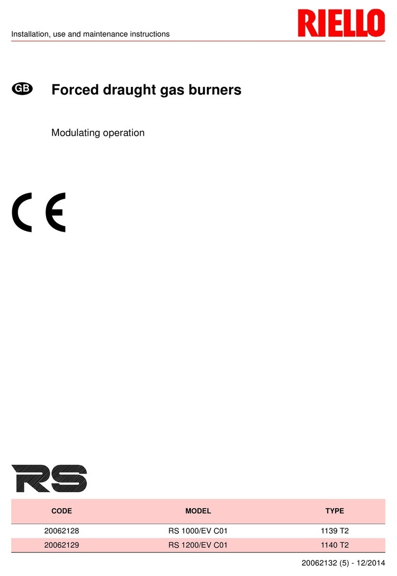
Istruzioni per installazione, uso e manutenzione
Montage, und Bedienungs Anleitung
Installation, use and maintenance instructions
Manuel d’entretien
Bruciatore di gasolio
Öl-Gebläsebrenner
Light oil burner
Brûleur fioul domestique
Funzionamento bistadio
Zweistufiger Betrieb
Two-stage operation
Fonctionnement à 2 allures
20016429 (3) - 05/2016
CODICE - CODE MODELLO - MODELL
MODEL - MODELE TIPO - TYP
TYPE - TYPE
20016419 RL 250 MZ 970 T80
I
D
GB
F
3
INDICE
Dati tecnici . . . . . . . . . . . . . . . . . . . . . . . . . . . . . . . . . . . pagina 4
Accessori . . . . . . . . . . . . . . . . . . . . . . . . . . . . . . . . . . . . . . . . . . . 4
Elenco modelli disponibili. . . . . . . . . . . . . . . . . . . . . . . . . . . . . . . 5
Descrizione bruciatore . . . . . . . . . . . . . . . . . . . . . . . . . . . . . . . . 12
Descrizione quadro elettrico. . . . . . . . . . . . . . . . . . . . . . . . . . . . 12
Imballo - Peso . . . . . . . . . . . . . . . . . . . . . . . . . . . . . . . . . . . . . . 14
Corredo . . . . . . . . . . . . . . . . . . . . . . . . . . . . . . . . . . . . . . . . . . . 14
Ingombro . . . . . . . . . . . . . . . . . . . . . . . . . . . . . . . . . . . . . . . . . . 14
Campi di lavoro . . . . . . . . . . . . . . . . . . . . . . . . . . . . . . . . . . . . . 16
Caldaie . . . . . . . . . . . . . . . . . . . . . . . . . . . . . . . . . . . . . . . . . . . . 16
Caldaia di prova . . . . . . . . . . . . . . . . . . . . . . . . . . . . . . . . . . . . . 16
Installazione . . . . . . . . . . . . . . . . . . . . . . . . . . . . . . . . . . . . . . . 18
Piastra caldaia . . . . . . . . . . . . . . . . . . . . . . . . . . . . . . . . . . . . . . 18
Lunghezza boccaglio . . . . . . . . . . . . . . . . . . . . . . . . . . . . . . . . . 18
Fissaggio del bruciatore alla caldaia . . . . . . . . . . . . . . . . . . . . . 18
Accessibilità parte interna testa . . . . . . . . . . . . . . . . . . . . . . . . . 18
Scelta degli ugelli per il 1° e 2 stadio . . . . . . . . . . . . . . . . . . . . . 18
Montaggio degli ugelli. . . . . . . . . . . . . . . . . . . . . . . . . . . . . . . . . 20
Posizione elettrodi . . . . . . . . . . . . . . . . . . . . . . . . . . . . . . . . . . . 20
Regolazione testa di combustione . . . . . . . . . . . . . . . . . . . . . . . 20
Alimentazione combustibile . . . . . . . . . . . . . . . . . . . . . . . . . . . . 22
Collegamenti idraulici . . . . . . . . . . . . . . . . . . . . . . . . . . . . . . . . . 22
Innesco pompa. . . . . . . . . . . . . . . . . . . . . . . . . . . . . . . . . . . . . . 24
Regolazione bruciatore . . . . . . . . . . . . . . . . . . . . . . . . . . . . . . . 24
Servomotore. . . . . . . . . . . . . . . . . . . . . . . . . . . . . . . . . . . . . . . . 26
Pressostato aria . . . . . . . . . . . . . . . . . . . . . . . . . . . . . . . . . . . . . 28
Controlli finali . . . . . . . . . . . . . . . . . . . . . . . . . . . . . . . . . . . . . . . 30
Manutenzione. . . . . . . . . . . . . . . . . . . . . . . . . . . . . . . . . . . . . . . 30
Funzionamento bruciatore . . . . . . . . . . . . . . . . . . . . . . . . . . . . . 32
Diagnostica programma di avviamento . . . . . . . . . . . . . . . . . . . 34
Sblocco apparecchiatura e utilizzo diagniostica. . . . . . . . . . . . . 34
Incovenienti - cause - rimedi . . . . . . . . . . . . . . . . . . . . . . . . . . . 38
Appendice
Schema quadro elettrico . . . . . . . . . . . . . . . . . . . . . . . . . . . . . . 42
I
INHALT
Technische Angaben . . . . . . . . . . . . . . . . . . . . . . . . . . . . Seite 6
Zubehör. . . . . . . . . . . . . . . . . . . . . . . . . . . . . . . . . . . . . . . . . . . . . 6
Verzeichnis der Modelle . . . . . . . . . . . . . . . . . . . . . . . . . . . . . . . . 7
Brennerbeschreibung . . . . . . . . . . . . . . . . . . . . . . . . . . . . . . . . . 13
Beschreibung der Schalttafel . . . . . . . . . . . . . . . . . . . . . . . . . . . 13
Verpackung - Gewicht. . . . . . . . . . . . . . . . . . . . . . . . . . . . . . . . . 15
Ausstatung . . . . . . . . . . . . . . . . . . . . . . . . . . . . . . . . . . . . . . . . . 15
Abmessungen . . . . . . . . . . . . . . . . . . . . . . . . . . . . . . . . . . . . . . . 15
Regelbereiche. . . . . . . . . . . . . . . . . . . . . . . . . . . . . . . . . . . . . . . 17
Kessel . . . . . . . . . . . . . . . . . . . . . . . . . . . . . . . . . . . . . . . . . . . . . 17
Prüfkessel . . . . . . . . . . . . . . . . . . . . . . . . . . . . . . . . . . . . . . . . . . 17
Installation . . . . . . . . . . . . . . . . . . . . . . . . . . . . . . . . . . . . . . . . . 19
Kesselplatte. . . . . . . . . . . . . . . . . . . . . . . . . . . . . . . . . . . . . . . . . 19
Flammrohrlänge . . . . . . . . . . . . . . . . . . . . . . . . . . . . . . . . . . . . . 19
Befestigung des Brenners am Heizkessel . . . . . . . . . . . . . . . . . 19
Zugänglichkeit zum Innenteil des Flammkopfs . . . . . . . . . . . . . . 19
Wahl der Düsen für 1. und 2. Stufe. . . . . . . . . . . . . . . . . . . . . . . 19
Düsenmontage . . . . . . . . . . . . . . . . . . . . . . . . . . . . . . . . . . . . . . 21
Position der Elektroden. . . . . . . . . . . . . . . . . . . . . . . . . . . . . . . . 21
Einstellung des Flammkopf. . . . . . . . . . . . . . . . . . . . . . . . . . . . . 21
Brennstoffzuführung . . . . . . . . . . . . . . . . . . . . . . . . . . . . . . . . . . 23
Hydraulikanschlüsse . . . . . . . . . . . . . . . . . . . . . . . . . . . . . . . . . . 23
Einschalten der Pumpe. . . . . . . . . . . . . . . . . . . . . . . . . . . . . . . . 25
Brennereinstellung . . . . . . . . . . . . . . . . . . . . . . . . . . . . . . . . . . . 25
Stellantrieb . . . . . . . . . . . . . . . . . . . . . . . . . . . . . . . . . . . . . . . . . 27
Luftdruckwächter. . . . . . . . . . . . . . . . . . . . . . . . . . . . . . . . . . . . . 29
Endkontrollen . . . . . . . . . . . . . . . . . . . . . . . . . . . . . . . . . . . . . . . 31
Wartung. . . . . . . . . . . . . . . . . . . . . . . . . . . . . . . . . . . . . . . . . . . . 31
Brennerbetrieb . . . . . . . . . . . . . . . . . . . . . . . . . . . . . . . . . . . . . . 33
Diagnostik Betriebsablauf . . . . . . . . . . . . . . . . . . . . . . . . . . . . . . 35
Entriegelung des Steuergeräts und Verwendung der Diagnostik 35
Störungen - Ursachen - Abhilfen. . . . . . . . . . . . . . . . . . . . . . . . . 39
Anhang
Schaltplan . . . . . . . . . . . . . . . . . . . . . . . . . . . . . . . . . . . . . . . . . . 42
D
CONTENTS
Technical data. . . . . . . . . . . . . . . . . . . . . . . . . . . . . . . . . . .page 8
Accessories . . . . . . . . . . . . . . . . . . . . . . . . . . . . . . . . . . . . . . . . . 8
List of available models . . . . . . . . . . . . . . . . . . . . . . . . . . . . . . . . 9
Burner description . . . . . . . . . . . . . . . . . . . . . . . . . . . . . . . . . . . 13
Description of panel board . . . . . . . . . . . . . . . . . . . . . . . . . . . . . 13
Packaging - Weight . . . . . . . . . . . . . . . . . . . . . . . . . . . . . . . . . . 15
Standard equipment . . . . . . . . . . . . . . . . . . . . . . . . . . . . . . . . . . 15
Max. dimensions . . . . . . . . . . . . . . . . . . . . . . . . . . . . . . . . . . . . 15
Firing rates . . . . . . . . . . . . . . . . . . . . . . . . . . . . . . . . . . . . . . . . . 17
Boilers . . . . . . . . . . . . . . . . . . . . . . . . . . . . . . . . . . . . . . . . . . . . 17
Test boiler. . . . . . . . . . . . . . . . . . . . . . . . . . . . . . . . . . . . . . . . . . 17
Installation . . . . . . . . . . . . . . . . . . . . . . . . . . . . . . . . . . . . . . . . 19
Boiler plate . . . . . . . . . . . . . . . . . . . . . . . . . . . . . . . . . . . . . . . . . 19
Blast tube length. . . . . . . . . . . . . . . . . . . . . . . . . . . . . . . . . . . . . 19
Securing the burner to the boiler . . . . . . . . . . . . . . . . . . . . . . . . 19
Accessibility to the interior of the combustion head . . . . . . . . . . 19
Choice of nozzles for the 1st and 2nd stage . . . . . . . . . . . . . . . 19
Nozzle assembly . . . . . . . . . . . . . . . . . . . . . . . . . . . . . . . . . . . . 21
Position of electrodes. . . . . . . . . . . . . . . . . . . . . . . . . . . . . . . . . 21
Combustion head setting . . . . . . . . . . . . . . . . . . . . . . . . . . . . . . 21
Fuel supply. . . . . . . . . . . . . . . . . . . . . . . . . . . . . . . . . . . . . . . . . 23
Hydraulic connections . . . . . . . . . . . . . . . . . . . . . . . . . . . . . . . . 23
Pump priming . . . . . . . . . . . . . . . . . . . . . . . . . . . . . . . . . . . . . . . 25
Burner calibration . . . . . . . . . . . . . . . . . . . . . . . . . . . . . . . . . . . . 25
Servomotor. . . . . . . . . . . . . . . . . . . . . . . . . . . . . . . . . . . . . . . . . 27
Air pressure switch. . . . . . . . . . . . . . . . . . . . . . . . . . . . . . . . . . . 29
Final checks . . . . . . . . . . . . . . . . . . . . . . . . . . . . . . . . . . . . . . . . 31
Maintenance. . . . . . . . . . . . . . . . . . . . . . . . . . . . . . . . . . . . . . . . 31
Burner operation. . . . . . . . . . . . . . . . . . . . . . . . . . . . . . . . . . . . . 33
Start-up cycle diagnostics. . . . . . . . . . . . . . . . . . . . . . . . . . . . . . 36
Resetting the control box and using diagnostics . . . . . . . . . . . . 36
Faults - Probable cause - Suggested remedy . . . . . . . . . . . . . . 40
Appendix
Panel board layout . . . . . . . . . . . . . . . . . . . . . . . . . . . . . . . . . . . 42
GB
INDEX
Données techniques. . . . . . . . . . . . . . . . . . . . . . . . . . . . page 10
Accessoires. . . . . . . . . . . . . . . . . . . . . . . . . . . . . . . . . . . . . . . . . 10
Modèles disponibles . . . . . . . . . . . . . . . . . . . . . . . . . . . . . . . . . . 11
Description brûleur . . . . . . . . . . . . . . . . . . . . . . . . . . . . . . . . . . . 13
Description tableau électrique. . . . . . . . . . . . . . . . . . . . . . . . . . . 13
Emballage - Poids. . . . . . . . . . . . . . . . . . . . . . . . . . . . . . . . . . . . 15
Equipement standard . . . . . . . . . . . . . . . . . . . . . . . . . . . . . . . . . 15
Encombrement . . . . . . . . . . . . . . . . . . . . . . . . . . . . . . . . . . . . . . 15
Plages de puissance. . . . . . . . . . . . . . . . . . . . . . . . . . . . . . . . . . 17
Chaudières . . . . . . . . . . . . . . . . . . . . . . . . . . . . . . . . . . . . . . . . . 17
Chaudière d’essai . . . . . . . . . . . . . . . . . . . . . . . . . . . . . . . . . . . . 17
Installation . . . . . . . . . . . . . . . . . . . . . . . . . . . . . . . . . . . . . . . . . 19
Plaque chaudière . . . . . . . . . . . . . . . . . . . . . . . . . . . . . . . . . . . . 19
Longueur buse . . . . . . . . . . . . . . . . . . . . . . . . . . . . . . . . . . . . . . 19
Fixation du brûleur à la chaudière. . . . . . . . . . . . . . . . . . . . . . . . 19
Possibilité d’accéder à la partie interne de la tête de combustion. 19
Choix des gicleurs pour 1ère et 2ème allure. . . . . . . . . . . . . . . . 19
Montage des gicleurs . . . . . . . . . . . . . . . . . . . . . . . . . . . . . . . . . 21
Position des électrodes. . . . . . . . . . . . . . . . . . . . . . . . . . . . . . . . 21
Réglage tête de combustion . . . . . . . . . . . . . . . . . . . . . . . . . . . . 21
Alimentation combustible . . . . . . . . . . . . . . . . . . . . . . . . . . . . . . 23
Raccordements hydrauliques . . . . . . . . . . . . . . . . . . . . . . . . . . . 23
Amorçage pompe . . . . . . . . . . . . . . . . . . . . . . . . . . . . . . . . . . . . 25
Réglage brûleur) . . . . . . . . . . . . . . . . . . . . . . . . . . . . . . . . . . . . . 25
Servomoteur . . . . . . . . . . . . . . . . . . . . . . . . . . . . . . . . . . . . . . . . 27
Pressostat de l’air . . . . . . . . . . . . . . . . . . . . . . . . . . . . . . . . . . . . 29
Contrôles finaux . . . . . . . . . . . . . . . . . . . . . . . . . . . . . . . . . . . . . 31
Entretien . . . . . . . . . . . . . . . . . . . . . . . . . . . . . . . . . . . . . . . . . . . 31
Fonctionnement brûleur . . . . . . . . . . . . . . . . . . . . . . . . . . . . . . . 33
Diagnostic cycle de démarrage. . . . . . . . . . . . . . . . . . . . . . . . . . 37
Déblocage du coffret de sécurité et utilisation de la
fonction diagnostic . . . . . . . . . . . . . . . . . . . . . . . . . . . . . . . . . . . 37
Inconvénients, causes probables, remèdes conseillés. . . . . . . . 41
Annexe
Schéma tableau électrique . . . . . . . . . . . . . . . . . . . . . . . . . . . . . 42

F
4
DATI TECNICI
(1)
Condizioni di riferimento: Temperatura ambiente 20°C - Pressione barometrica 1000 mbar - Altitudine 100 m s.l.m.
(2)
Pressione sonora misurata nel laboratorio combustione del costruttore, con bruciatore funzionante su caldaia di prova, alla potenza massima.
La Potenza sonora è misurata col metodo “Free Field”, previsto dalla Norma EN 15036, e secondo una accuratezza di misura “Accuracy:
Category 3”, come descritto dalla Norma EN ISO 3746.
ACCESSORI
(su richiesta)
MODELLO RL 250 MZ
TIPO 970 T80
POTENZA
(1)
PORTATA
(1)
2° stadio
(min - max) kW
kg/h 1250 ÷ 2700
106 ÷ 228
1° stadio
(min) kW
kg/h 600
51
COMBUSTIBILE GASOLIO
- potere calorifico inferiore kWh/kg
Mcal/kg 11,8
10,2 (10.200 kcal/kg)
- densità kg/dm30,82 - 0,85
- viscosità a 20 °C mm2/s max 6 (1,5 °E - 6 cSt)
FUNZIONAMENTO - Intermittente (min. 1 arresto in 24 ore)
- Bistadio (alta e bassa fiamma) e monostadio (tutto - niente)
UGELLI numero 2
IMPIEGO STANDARD Caldaie: ad acqua, a vapore, ad olio diatermico
TEMPERATURA AMBIENTE °C 0 - 40
TEMPERATURA ARIA COMBURENTE °C max 60
ALIMENTAZIONE ELETTRICA 3~ 380V +/-10% 60 Hz 1N~ 220V 60 Hz
MOTORI ELETTRICI rpm 3480
MOTORE VENTILATORE V
kW
A
220-230/380-400
7,5
25,6 - 24,9/14,8 - 14,4
MOTORE POMPA V
W
A
230
550
3,6
TRASFORMATORE D’ACCENSIONE V1 - V2
I1 - I2 230 V - 2 x 5 kV
1,9 A - 35 mA
POMPA portata a 12 bar (kg/h)
campo di pressione (bar)
temperatura combustibile (°C)
230
10-21
90
POTENZA ELETTRICA ASSORBITA kW max 8,8
GRADO DI PROTEZIONE IP 44
CONFORMITÀ DIRETTIVE CE 2006/42 - 2004/108 - 2006/95
RUMOROSITÀ
(2)
Pressione sonora
Potenza sonora dBA 85,4
96,4
•
KIT INTERFACCIA DIAGNOSTICA codice 3002719
•
KIT CASSONE SILENZIATORE codice 3000779
•
KIT TESTA LUNGA codice 3010422
5
DESIGNAZIONE BRUCIATORI SERIE RL
Serie : R
Grandezza
Combustibile : S
L
LS
Gas naturale
Gasolio
Gasolio / Metano
Regolazione :
Testa : TC Testa standard
TL Testa lunga
Sistema di controllo fiamma :
FS1
FS2 Standard (1 stop ogni 24 h)
Funzionamento continuo (1 stop ogni 72 h)
Alimentazione elettrica del sistema :
3/400/50
3/230/50
Tensione ausiliari :
230/50/60
110/50/60
R L 250 TC
Emissione : ... Classe 1 EN267 - EN676
MZ Classe 2 EN267 - EN676
BLU Classe 3 EN267 - EN676
MX Classe 2 EN267
Classe 3 EN676
FS1 380/60 230/50/60
DESIGNAZIONE BASE
DESIGNAZIONE ESTESA
ELENCO MODELLI DISPONIBILI
Designazione Tensione Avviamento Codice
RL 250 MZ 380V-60Hz Diretto 20016419
3N / 400V / 50Hz
3 / 230V / 50Hz
230V / 50-60Hz
110V / 50-60Hz
N Nafta
E Camma elettronica
EV Camma elettronica e velocità variabile (con Inverter)
P Valvola proporzionale aria/gas
B Bistadio
MZ
6
TECHNISCHE ANGABEN
(1)
Bezugsbedingungen: Raumtemperatur 20°C - Barometrischer Druck 1000 mbar - Höhe 100 m ü.d.M.
(2)
Schalldruck gemessen im Verbrennungslabor des Herstellers bei laufendem Brenner am Prüfkessel, bei Höchstleistung.
Die Schallleistung wird mit der von der Norm EN 15036 vorgesehenen “Free Field” Methode und mit einer Messgenauigkeit “Accuracy:
Category 3”, wie von der Norm EN ISO 3746 vorgesehen, gemessen.
ZUBEHÖR
(auf Wunsch)
MODELL RL 250 MZ
TYP 970 T80
LEISTUNG
(1)
DURCHSATZ
(1)
2. Stufe
(MIN - MAX) kW
kg/h 1250 ÷ 2700
106 ÷ 228
1. Stufe
(MIN) kW
kg/h 600
51
BRENNSTOFF HEIZÖL EL
- Heizwert Hu kWh/kg
Mcal/kg 11,8
10,2 (10.200 kcal/kg)
- Dichte kg/dm30,82 - 0,85
- Viskosität bei 20 °C mm2/s max 6 (1,5 °E - 6 cSt)
BETRIEB - Aussetzend (min. 1 Halt in 24 Std)
- Zweistufig (hohe und niedrige Flamme) - einstufig (alles - nichts)
DÜSEN Stück 2
STANDARDEINSATZ Heizkessel: mit Wasser, Dampf, diathermischem Öl
RAUMTEMPERATUR °C 0 - 40
TEMPERATUR VERBRENNUNGSLUFT °C max 60
ELEKTRISCHE SPEISUNG 3~ 380V +/-10% 60 Hz 1N~ 220V 60 Hz
ELEKTROMOTOREN rpm 3480
GEBLÄSEMOTOR V
kW
A
220-230/380-400
7,5
25,6 - 24,9/14,8 - 14,4
PUMPENMOTOR V
W
A
230
550
3,6
ZÜNDTRANSFORMATOR V1 - V2
I1 - I2 230 V - 2 x 5 kV
1,9 A - 35 mA
PUMPE Fördermenge bei 12 bar (kg/h)
Druckbereich (bar)
Brennstofftemperatur (°C)
230
10-21
90
ELEKTRISCHE LEISTUNGSAUFNAHME kW max 8,8
SCHUTZART IP 44
CE-NORMGERECHT 2006/42 - 2004/108 - 2006/95
SCHALLDRUCKPEGEL
(2)
Schalldruckpegel
Schalleistung dBA 85,4
96,4
•
KIT DIAGNOSESCHNITTSTELLE Code 3002719
•
KIT SCHALLDÄMMUNGSKASTEN Code 3000779
•
KIT
LANGER KOPF Code 3010422
7
BEZEICHNUNG DER BRENNER DER SERIE RL
Serie : R
Baugröße
Brennstoff : S
L
LS
Erdgas
Heizöl EL
Zweistoffbrenner Heizöl / Erdgas
Einstellung :
Flammkopf : TC Standardkopf
TL Verlängerter Kopf
Flammenüberwachung :
FS1
FS2 Standard intermittierend (min. 1 Abschaltung in 24 Std)
Dauerbetrieb (1 Abschaltung in 72 Std)
Stromversorgung des Systems :
3/400/50
3/230/50
Spannung der Hilfskreise :
230/50/60
110/50/60
R L 250 TC
Emission : ... Klasse 1 EN267 - EN676
MZ Klasse 2 EN267 - EN676
BLU Klasse 3 EN267 - EN676
MX Klasse 2 EN267
Klasse 3 EN676
FS1 380/60 230/50/60
BASISBEZEICHNUNG
ERWEITERTE BEZEICHNUNG
VERZEICHNIS DER MODELLE
Bezeichnung
Stromversorgung Schaltung Code
RL 250 MZ 380V-60Hz Direkt 20016419
3N / 400V / 50Hz
3 / 230V / 50Hz
230V / 50-60Hz
110V / 50-60Hz
N Erdöl
E Elektronischer Nocken
EV Elektronischer Nocken und variable Geschwindigkeit (mit Inverter)
P Luft/Gas Proportionalventil
B Zweistufig
MZ
8
TECHNICAL DATA
(1)
Reference conditions: Ambient temperature 20°C - Barometric pressure 1000 mbar - Altitude 100 m a.s.l.
(2)
Sound pressure measured in manufacturer's combustion laboratory, with burner operating on test boiler and at maximum rated output.
The sound power is measured with the “Free Field” method, as per EN 15036, and according to an “Accuracy: Category 3” measuring accu-
racy, as set out in EN ISO 3746.
ACCESSORIES
(optional)
MODEL RL 250 MZ
TYPE 970 T80
OUTPUT
(1)
DELIVERY
(1)
2nd stage
(min - max) kW
kg/h 1250 ÷ 2700
106 ÷ 228
1st stage
(min) kW
kg/h 600
51
FUEL LIGHT OIL
- net calorific value kWh/kg
Mcal/kg 11.8
10.2 (10.200 kcal/kg)
- density kg/dm30.82 - 0.85
- viscosity at 20 °C mm2/s max 6 (1.5 °E - 6 cSt)
OPERATION - Intermittent (min. 1 stop in 24 hours)
- Two-stage (high and low flame) and single-stage (all - nothing)
NOZZLES number 2
STANDARD APPLICATIONS Boilers: water, steam, diathermic oil
AMBIENT TEMPERATUR °C 0 - 40
COMBUSTION AIR TEMPERATURE °C max 60
ELECTRICAL SUPPLY 3~ 380V +/-10% 60 Hz 1N~ 220V 60 Hz
ELECTRIC MOTORS rpm 3480
FAN MOTOR V
kW
A
220-230/380-400
7,5
25.6 - 24.9/14.8 - 14.4
PUMP MOTOR V
W
A
230
550
3,6
IGNITION TRANSFORMER V1 - V2
I1 - I2 230 V - 2 x 5 kV
1.9 A - 35 mA
PUMP delivery at 12 bar (kg/h)
pressure range (bar)
fuel temperatur (°C)
230
10-21
90
ELECTRICAL POWER CONSUMPTION kW max 8.8
ELECTRICAL PROTECTION IP 44
CONFORMITY TO EEC DIRECTIVES 2006/42 - 2004/108 - 2006/95
NOISE LEVELS
(2)
Sound pressure
Sound power dBA 85.4
96.4
•
DIAGNOSTICS INTERFACE KIT Code 3002719
•
SILENCER BOX KIT Code 3000779
•
LONG HEAD KIT Code 3010422
9
DESIGNATION OF BURNER SERIES RL
Series : R
Size
Fuel : S
L
LS
Natural gas
Light oil
Light oil / Methane
Setting :
Head : TC Standard head
TL Extended head
Flame control system :
FS1
FS2 Standard (1 stop every 24 h)
Continuos working (1 stop every 72 h)
Electrical supply to the system :
3/400/50
3/230/50
Auxiliary voltage :
230/50/60
110/50/60
R L 250 TC
Emission : ... Class 1 EN267 - EN676
MZ Class 2 EN267 - EN676
BLU Class 3 EN267 - EN676
MX Class 2 EN267
Class 3 EN676
FS1 380/60 230/50/60
BASIC DESIGNATION
EXTENDED DESIGNATION
LIST OF AVAILABLE MODELS
Designation Electrical supply Starting Code
RL 250 MZ 380V-60Hz Direct 20016419
3N / 400V / 50Hz
3 / 230V / 50Hz
230V / 50-60Hz
110V / 50-60Hz
N Heavy oil
E Electronic cam
EV Electronic cam and variable speed (with Inverter)
P Air/gas proportioning valve
B Two-stage
MZ
10
DONNÉES TECHNIQUES
(1)
Conditions de référence: Température ambiante 20°C - Pression barométrique 1000 mbar - Altitude 100 m au-dessus du niveau de la mer.
(2)
Pression sonore mesurée dans le laboratoire de combustion du constructeur, avec le brûleur fonctionnant sur la chaudière d'essai, à la puis-
sance maximale. La puissance sonore est mesurée grâce à la méthode en « champ libre », prévue par la norme EN 15036, et conformément
à la précision de mesure « Précision : Catégorie 3 », comme décrit par norme EN ISO 3746.
ACCESSOIRES
(sur demande)
MODELE RL 250 MZ
TYPE 970 T80
PUISSANCE
(1)
DEBIT
(1)
2ème allure
(min - max) kW
kg/h 1250 ÷ 2700
106 ÷ 228
1ère allure
(min) kW
kg/h 600
51
COMBUSTIBLE FIOUL DOMESTIQUE
- pouvoir calorifique inférieur kWh/kg
Mcal/kg 11,8
10,2 (10.200 kcal/kg)
- densité kg/dm30,82 - 0,85
- viscosité à 20°C mm2/s max 6 (1,5 °E - 6 cSt)
FONCTIONNEMENT - Intermittent (1 arrêt min en 24 heures)
- 2 allures (flamme haute et basse) et une allure (tout - rien)
GICLEURS numero 2
EMPLOI STANDARD Chaudières à eau, à vapeur, à huile diathermique
TEMPERATURE AMBIANTE °C 0 - 40
TEMPERATURE AIR COMBURANT °C max 60
ALIMENTATION ÉLECTRIQUES 3~ 380V +/-10% 60 Hz 1N~ 220V 60 Hz
MOTEURS ELECTRIQUES rpm 3480
MOTEUR VENTILATEUR V
kW
A
220-230/380-400
7,5
25,6 - 24,9/14,8 - 14,4
MOTEUR POMPE V
W
A
230
550
3,6
TRANSFORMATEUR D’ALLUMAGE V1 - V2
I1 - I2 230 V - 2 x 5 kV
1,9 A - 35 mA
POMPE débit à 12 bar (kg/h)
plage de pression (bar)
température combustible (°C)
230
10-21
90
PUISSANCE ELECTRIQUE ABSORBEE kW max 8,8
DEGRE DE PROTECTION IP 44
CONFORMÉMENT AUX DIRECTIVES CEE 2006/42 - 2004/108 - 2006/95
NIVEAU DE BRUIT
(2)
Pression sonore
Puissance sonore dBA 85,4
96,4
•
KIT INTERFACE DIAGNOSTIC Code 3002719
•
KIT CAISSON SILENCIEUX Code 3000779
•
KIT
TETE LONGUE Code 3010422
11
DESIGNATION BRULEURS SERIE RL
Série : R
Dimension
Combustible : S
L
LS
Gaz naturel
Fioul
Fioul / Méthane
Régulation : E Came électronique
EV Came électronique et moteur à fréquence variable (avec Variateur de fréquence)
Tête : TC Tête standard
TL Tête longue
Système de contrôle flamme :
FS1
FS2 Standard (1 arrêt min en 24 heures)
Fonctionnement continuos (1 arrêt min en 72 heures)
Alimentation électrique du système :
3/400/50
3/230/50
Tension auxiliaires :
230/50/60
110/50/60
R L 250 TC
Émission : ... Classe 1 EN267 - EN676
MZ Classe 2 EN267 - EN676
BLU Classe 3 EN267 - EN676
MX Classe 2 EN267
Classe 3 EN676
FS1 380/60 230/50/60
DESIGNATION BASE
DESIGNATION ELARGIE
MODELES DISPONIBLES
Designation Alimentation électrique Démarrage Code
RL 250 MZ 380V-60Hz Direct 20016419
3N / 400V / 50Hz
3 / 230V / 50Hz
230V / 50-60Hz
110V / 50-60Hz
N Fioul
P Soupape proportionnelle air/ gaz
B Deux allures
MZ
12
DESCRIZIONE BRUCIATORE (A)
1 Girante
2 Motore ventilatore
3 Servomotore serrande aria
4 Testa di combustione
5 Elettrodi di accensione
6 Disco di stabilità fiamma
7 Cofano quadro elettrico
8 Ingresso aria ventilatore
9 Manicotto
10 Schermo per fissaggio alla caldaia
11 Otturatore
12 Presa di pressione aria testa di combustione
13 Pompa
14 Fotoresistenza
15 Motore pompa
16 Gruppo valvole
17 Vite per regolazione testa di combustione
DESCRIZIONE QUADRO ELETTRICO (B)
1 Pressostato aria
2 Relè contatti puliti
3 Apparecchiatura elettrica
4 Due interruttori elettrici:
- uno per “acceso - spento bruciatore”
- uno per “1° - 2° stadio”
5 Morsettiera
6 Contattore motore e relè termico con pul-
sante di sblocco
7 Relè motore pompa
8 Trasformatore d’accensione
9 Passaggio cavi di alimentazione e collega-
menti esterni
NOTA
Vi sono due possibilità di blocco del bruciatore:
Blocco apparecchiatura: l’accensione del pul-
sante (led rosso) dell’apparecchiatura 3)(B)
avverte che il bruciatore è in blocco.
Per sbloccare premere il pulsante per un tempo
compreso tra 1 e 3 secondi.
Blocco motore: per sbloccare premere il pul-
sante del relè termico.
(A)
(B)
D3940
20108741
3
4
5
6
7
8
11
12
14
15
17
2
13
16
1
9
10
1
2
3
4
5
6
8
7
9
13
BRENNERBESCHREIBUNG (A)
1 Gebläserad
2 Gebläsemotor
3 Luftklappestellantrieb
4 Flammkopf
5 Zündelektroden
6 Stauscheibe
7 Verkleidung der Schalttafel
8 Lufteinlaß zum Gebläse
9 Muffe
10 Wärmeschild für Befestigung am Heizkessel
11 Schieber
12 Luftdruckentnahmestelle
13 Pumpe
14 Foto-Widerstand
15 Pumpenmotor
16 Ventilgruppe
17 Einstellschraube des Flammkopfes
BESCHREIBUNG DER SCHALTTAFEL (B)
1 Luftdruckwächter
2 Relais mit Reinkontakten
3 Steuergerät
4 Zwei Schalter:
- einer für “Brenner eingeschaltet-ausgeschaltet”
- einer für “1. - 2. Stufe”
5 Klemmenbrett
6 Motorschaltglied und Wärmerelais mit Entrie-
gelungsschalter
7 Pumpenmotor-Relais
8 Zündtransformator
9 Durchgang für Versorgungskabel und
externe Verbindungen
MERKE
Die Störabschaltungen des Brenners können
zweierlei Art sein:
Störabschaltung des Gerätes: das Aufleuch-
ten der Drucktaste (rote Led) am Steuergerät
3)(B) weist auf eine Störabschaltung des Bren-
ners hin.
Zur Entriegelung den Druckknopf für eine Zeit
zwischen 1 und 3 Sekunden drücken.
Störabschaltung des Motors: Entriegelung
durch Betätigen des Druckknopfs des Thermo-
relais.
BURNER DESCRIPTION (A)
1 Fan
2 Fan motor
3 Air gate valve servomotor
4 Combustion head
5 Ignition electrodes
6 Flame stability disk
7 Panel board - cover
8 Air inlet to fan
9 Manifold
10 Thermal insulation screen for securing
burner to boiler
11 Shutter
12 Air pressure test point
13 Pump
14 Photoelectric cell
15 Pump motor
16 Valve group
17 Screw for combustion head adjustment
DESCRIPTION OF PANEL BOARD (B)
1 Air pressure switch
2 Voltage free contacts relay
3 Control box
4 Two switches:
- one “burner off - on”
- one for “1st - 2nd stage operation”
5 Main supply terminal strip
6 Motor contactor and thermal cut-out with
reset button
7 Pump motor relay
8 Ignition transformer
9 Entry for power cables and external leads
N.B.
Two types of burner failure may occur:
Control box lock-out: if the control box 3)(B)
pushbutton (red led) lights up, it indicates that
the burner is in lock-out.
To reset, hold the pushbutton down for between
1 and 3 seconds.
Motors trip: release by pressing the push but-
ton of the thermal cutout relay.
DESCRIPTION BRULEUR (A)
1 Turbine
2 Moteur ventilateur
3 Servomoteur volet d’air
4 Tête de combustion
5 Electrodes d’allumage
6 Disque de stabilité de flamme
7 Capot tableau électrique
8 Entrée air dans le ventilateur
9 Manchon
10 Ecran thermique pour fixation à la chaudière
11 Obturateur
12 Prise de pression air tête de combustion
13 Pompe
14 Cellule photorésistance
15 Moteur pompe
16 Groupe vannes
17 Vis pour réglage tête de combustion
DESCRIPTION TABLEAU ELECTRIQUE (B)
1 Pressostat air
2 Relais contacts propres
3 Coffret de sécurité
4 Deux interrupteurs électriques:
- un pour “allumé - éteint brûleur”
- un pour “1ère - 2ème allure”
5 Plaque à bornes alimentation principale
6 Contacteur moteur et relais thermique avec
bouton de déblocage
7 Relais moteur pompe
8 Transformateur d’allumage
9 Passage des câbles d’alimentation et bran-
chements externes
NOTE
Il existe deux types de blocage du brûleur:
Blocage coffret: l'allumage du bouton (led
rouge) du coffret de sécurité 3)(B) signale que
le brûleur s'est bloqué.
Pour le débloquer appuyer sur le bouton pen-
dant un temps compris entre 1 et 3 secondes.
Blocage moteur: pour le débloquer appuyer
sur le bouton du relais thermique.
14
IMBALLO - PESO (A)
- misure indicative
• L’ imballo del bruciatore appoggia su una
pedana in legno particolarmente adatta ai car-
relli elevatori. Le dimensioni di ingombro
dell'imballo sono riportate nella tabella (A).
• Il peso del bruciatore completo di imballo è
indicato nella tabella (A).
CORREDO
1 - Schermo termico
4 - Viti per fissare la flangia del bruciatore alla
caldaia: M 16 x 40
1 - Istruzione
1 - Catalogo ricambi
INGOMBRO (B)
- misure indicative
L'ingombro del bruciatore è riportato in fig. (B).
Tener presente che per ispezionare la testa di
combustione il bruciatore deve essere aperto
arretrando la parte posteriore sui perni.
L'ingombro del bruciatore aperto è indicato dalla
quota M.
(A)
BA
D
E
M
G
L
H
mm A B C kg
RL 250 MZ 1400 725 1040 140
mm A B D E G H L M
RL 250 MZ 705 378 222 436 910 596 432 1163
(B)
D36
D3943
15
VERPACKUNG - GEWICHT (A)
- Richt-
werte
• Der Brenner steht auf einem besonders für-
die Handhabung mit Hubwagen geeignetem
Holzrahmen. Die Außenabmessungen der Ver-
packung sind in Tabelle (A) aufgeführt.
• Das Gesamtgewicht des Brenners ein-
schließlich Verpackung wird aus Tabelle (A)
ersichtlich.
AUSSTATUNG
1 - Wärmeschild
4 - Schrauben für die Befestigung des Bren-
nerflanschs am Kessel: M 16 x 40
1 - Anleitung
1 - ErsatzteileKatalog
ABMESSUNGEN (B)
- Richtwerte
Die Brennerabmessungen sind in der Abb. (B)
angeführt. Zur Inspektion des Flammkopfes
muß der Brenner geöffnet werden, indem der
hintere Teil auf den Zapfen zurück bewegt wird.
Die Gesamtabmessungen des offenen Bren-
ners sind unter dem Wert M angegeben.
PACKAGING - WEIGHT (A)
- Approximate
measurements
• The burner stands on a wooden base which
can be lifted by fork-lifts. Outer dimensions of
packaging are indicated in (A).
• The weight of the burner complete with pack-
aging is indicated in Table (A).
STANDARD EQUIPMENT
1 - Thermal insulation screen
4 - Screws to secure the burner flange to the
boiler: M 16 x 40
1 - Instruction booklet
1 - Spare parts list
MAX. DIMENSIONS (B)
-Approximate
measurements
The maximum dimensions of the burner are
given in (B). Bear in mind that inspection of the
combustion head requires the burner to be
opened by pulling the rear part back on the piv-
ots.
The overall dimensions of the burner when open
are indicated by M.
EMBALLAGE - POIDS (A)
- Mesures indica-
tives
• Le brûleur est placé sur une palette qui peut
être soulevée par des chariots transpalettes.
Les dimensions d’encombrement de l’embal-
lage sont reportées dans le tableau (A).
• Le poids du brûleur avec son emballage est
indiqué dans le tab. (A).
EQUIPEMENT STANDARD
1 - Ecran thermique
4 - Vis pour fixer la bride du brûleur à la chau-
dière: M 16 x 40
1 - Instructions
1 - Catalogue pièces détachées
ENCOMBREMENT (B)
- Mesures indicatives
L'encombrement du brûleur est indiqué sur la
fig. (B). Attention: pour contrôler la tête de com-
bustion, ouvrir le brûleur en faisant reculer
l'arrière sur les pivots.
L'encombrement du brûleur ouvert est indiqué
par la dimension M.
16
CAMPI DI LAVORO (A)
La PORTATA del 1° stadio va scelta entro
l'area A dei diagrammi a lato.
La PORTATA del 2° stadio va scelta entro
l'area B. Quest' area fornisce la portata mas-
sima del bruciatore in funzione della pressione
in camera di combustione.
Attenzione: il CAMPO DI LAVORO è stato rica-
vato alla temperatura ambiente di 20 °C, alla
pressione barometrica di 1000 mbar (circa 100
m s.l.m.) e con la testa di combustione regolata
come indicato a pag. 20.
CALDAIE (B)
L'abbinamento bruciatore-caldaia non pone pro-
blemi se la caldaia è omologata CE e le dimen-
sioni della sua camera di combustione sono vicine
a quelle indicate dal diagramma (B).
Se invece il bruciatore deve essere applicato ad
una caldaia non omologata CE e/o con dimen-
sioni della camera di combustione nettamente
più piccole di quelle indicate dal diagramma (B),
consultare i costruttori.
CALDAIA DI PROVA (B)
I campi di lavoro sono stati ricavati in speciali
caldaie di prova, secondo la norma EN 267.
Riportiamo in (B) diametro e lunghezza della
camera di combustione di prova.
Esempio:
Bruciatore RL 250 MZ
Potenza 1770 kW:
diametro 80 cm - lunghezza 3 m.
(A)
Cam. comb. / Feuerraum m
Comb. chamber / Chamb. comb
(B)
D1637
D3944
RL 250 MZ
mbar
20
18
16
14
12
10
8
6
4
2
0
kW
3200
2800
2400
2000
1600
1200800
400
-2
200
0
A B
17
REGELBEREICHE (A)
Der DURCHSATZ der 1. Stufe wird innerhalb
des Feldes A aus den nebenstehenden Kurven
ausgewählt.
Der DURCHSATZ der 2. Stufe wird innerhalb
des Feldes B ausgewählt. Dieses Feld zeigt den
Höchstdurchsatz des Brenners in Abhängigkeit
des Brennkammerdrucks.
Achtung: der REGELBEREICH wurde bei einer
Raumtemperatur von 20 °C, einem barometri-
schen Druck von 1000 mbar (ungefähr 100 m
ü.d.M.) und einem wie auf Seite 21 eingestellten
Flammkopf gemessen.
KESSEL (B)
Die Brenner-Kessel Kombination gibt keine Pro-
bleme, falls der Kessel "CE" - typgeprüft ist und
die Abmessungen seiner Brennkammer sich
den im Diagramm (B) angegebenen nähern.
Falls der Brenner dagegen an einem Kessel
angebracht werden muß, der nicht "CE"-typge-
prüft ist und/oder mit Abmessungen der Brenn-
kammer, die entschieden kleiner als jene in
Diagramm (B) angegebenen sind, sollten die
Hersteller zu Rate gezogen werden.
PRÜFKESSEL (B)
Die Regelbereiche wurden an speziellen Prüf-
kesseln entsprechend Norm EN 267 ermittelt.
In (B) sind Durchmesser und Länge der Prüf-
Brennkammer angegeben.
Beispiel:
Brenner RL 250 MZ
Leistung 1770 kW:
Durchmesser 80 cm - Länge 3 m.
FIRING RATES (A)
1st stage DELIVERY must be selected within
area A of the adjacent diagrams.
2nd stage DELIVERY must be selected within
area B. This area provides the maximum delivery
of the burner in relation to the pressure in the
combustion chamber.
Important: The FIRING RATE area values have
been obtained considering a surrounding tem-
perature of 20°C, and an atmospheric pressure
of 1000 mbar (approx. 100 m above sea level)
and with the combustion head adjusted as
shown on page 21.
BOILERS (B)
The burner/boiler matching does not pose any
problems if the boiler is CE type-approved and
its combustion chamber dimensions are similar
to those indicated in diagram (B).
If the burner must be combined with a boiler that
has not been CE type-approved and/or its com-
bustion chamber dimensions are clearly smaller
than those indicated in diagram (B), consult the
manufacturer.
TEST BOILER (B)
The firing rates were set in relation to special
test boilers, according to EN 267 regulations.
Figure (B) indicates the diameter and length of
the test combustion chamber.
Example:
RL 250 MZ burner
Output 1770 kW:
diameter 80 cm - length 3 m.
PLAGES DE PUISSANCE (A)
Le DEBIT de 1re allure doit être choisi dans la
plage A des diagrammes ci-contre.
Le DEBIT de 2éme allure doit être choisi dans
la plage B. Cette plage indique le débit maximum
du brûleur en fonction de la pression dans la
chambre de combustion.
Attention: La PLAGE DE PUISSANCE a été
calculée à une température ambiante de 20 °C,
à une pression barométrique de 1000 mbar
(environ 100 m au-dessus du niveau de la mer)
et avec la tête de combustion réglée comme
indiqué à la page 21.
CHAUDIERES (B)
L'accouplement brûleur-chaudière ne pose
aucun problème si la chaudière est homologuée
CE et si les dimensions de sa chambre de com-
bustion sont proches de celles indiquées dans
le diagramme (B).
Par contre, si le brûleur doit être accouplé à
une chaudière non homologuée CE et/ou avec
des dimensions de la chambre de combustion
plus petites que celles indiquées dans le
diagramme (B), consulter le constructeur.
CHAUDIERE D'ESSAI (B)
Les plages de puissance ont été établies sur
des chaudières d'essai spéciales, selon la
norme EN 267.
Nous reportons fig. (B) le diamätre et la lon-
gueur de la chambre de combustion d'essai.
Exemple:
Brûleur RL 250 MZ
Puissance 1770 kW:
diamètre 80 cm - longueur 3 m.
18
INSTALLAZIONE
L’INSTALLAZIONE DEL BRUCIATORE
DEVE ESSERE EFFETTUATA IN CON-
FORMITÀ ALLE LEGGI E NORMATIVE
LOCALI.
PIASTRA CALDAIA (A)
Forare la piastra di chiusura della camera di
combustione come in (A). La posizione dei fori
filettati può essere tracciata utilizzando lo
schermo termico a corredo del bruciatore.
LUNGHEZZA BOCCAGLIO (B)
La lunghezza del boccaglio va scelta secondo le
indicazioni del costruttore della caldaia e, in ogni
caso, deve essere maggiore dello spessore
della porta della caldaia, completa di refrattario.
Per le caldaie con giro dei fumi anteriore 1), o
con camera ad inversione di fiamma, eseguire
una protezione in materiale refrattario 5), tra
refrattario caldaia 2) e boccaglio 4).
La protezione deve consentire al boccaglio di
essere estratto.
Per le caldaie con il frontale raffreddato ad
acqua non è necessario il rivestimento refratta-
rio 2)-5)(B), se non vi è espressa richiesta del
costruttore della caldaia.
FISSAGGIO DEL BRUCIATORE ALLA
CALDAIA (B)
• Infilare lo schermo termico dato a corredo sul
boccaglio 4)(B).
• Infilare tutto il bruciatore sul foro caldaia, pre-
cedentemente predisposto, come in fig. (A), e
fissare con le viti date a corredo.
La tenuta bruciatore-caldaia deve essere
ermetica.
ACCESSIBILITÀ PARTE INTERNA
TESTA (C)
• Togliere il cofano di copertura del quadro elet-
trico.
• Svitare le viti 1).
• Togliere le prolunghe 3) dopo aver allentato il
tappo 2).
• Rimuovere le viti 4) e scollegare i tubetti di
adduzione del gasolio 6).
Nota. Fare attenzione alla possibile fuoriu-
scita di alcune gocce di combustibile durante
la fase di svitamento.
• Estrarre la testa di combustione 5).
SCELTA DEGLI UGELLI PER IL 1° E 2° STA-
DIO
Entrambi gli ugelli vanno scelti tra quelli indicati
nella tabella (D).
Il primo ugello determina la portata del brucia-
tore in 1° stadio.
Il secondo ugello funziona assieme al primo ed
entrambi determinano la portata del bruciatore
in 2° stadio.
Le portate del 1° e del 2° stadio devono essere
comprese tra i valori indicati a pag. 4.
Utilizzare ugelli con angolo di polverizzazione
60° alla pressione consigliata di 12 bar.
Generalmente i due ugelli sono di eguale por-
tata ma l'ugello del 1° stadio può avere una por-
tata inferiore al 50% della portata totale, quando
si desidera ridurre il picco di contro pressione al
momento dell'accensione (il bruciatore consente
buoni valori di combustione anche con rapporti
33 - 100% tra 1° e 2° stadio).
Esempio
Potenza caldaia = 1630 kW - rendimento 90 %
Potenza richiesta al bruciatore =
1630 : 0,9 = 1812 kW;
1812 : 2 = 906 kW per ugello
occorrono 2 ugelli uguali, 60°, 12 bar:
1° = 18 GPH - 2° = 18 GPH,
oppure due ugelli differenti:
1° = 15 GPH - 2° = 21 GPH.
NOTA
In alternativa agli ugelli indicati in tabella (D) è
possibile utilizzare ugelli tipo:
•DELAVAN B 60°;
•MONARCH PLP 70° (fino a 30 GPH).
5
2
1
1
4
123
45
6
mm A B C
RL 250 MZ 230 325 - 368 M16
(A)
(B)
(C)
D455
D3945
D3946
Ugello - Düse
Nozzle - Gicleur GPH kg/h kW
12 bar
10 bar 12 bar 14 bar
tipo - type
HAGO S-S 60°
12.0
13.0
14.0
15.0
16.0
17.0
18.0
19.0
20.0
22.0
24.0
25.0
26.0
28.0
30.0
32.0
34.0
35.0
44.16
47.84
51.52
55.20
58.88
62.57
66.25
69.93
73.61
80.97
88.33
92.00
95.69
103.05
110.41
117.77
125.13
128.81
48.73
52.79
56.86
60.92
64.98
69.04
73.10
77.16
81.22
89.34
97.47
101.53
105.59
113.71
121.83
129.95
138.08
142.14
52.96
57.38
61.79
66.20
70.62
75.03
79.44
83.86
88.27
97.10
105.93
110.34
114.75
123.58
132.41
141.24
150.06
154.48
582.36
630.89
679.42
727.95
776.48
825.01
873.54
922.07
970.60
1067.66
1164.72
1198.00
1261.78
1358.84
1455.90
1533.47
1629.31
1667.23
(D)
19
INSTALLATION
DER BRENNER MUSS IN ÜBEREIN-
STIMMUNG MIT DEN ÖRTLICHEN
GESETZEN UND VORSCHRIFTEN
INSTALLIERT SEIN.
KESSELPLATTE (A)
Die Abdeckplatte der Brennkammer wie in (A)
gezeigt vorbohren. Die Position der Gewinde-
bohrungen kann mit dem zur Grundausstattung
gehörenden Wärmeschild ermittelt werden.
FLAMMROHRLÄNGE (B)
Die Länge des Flammrohrs wird entsprechend
der Angaben des Kesselherstellers gewählt und
muß in jedem Fall größer als die Stärke der Kes-
seltür einschließlich feuerfestes Material sein.
Für Heizkessel mit vorderem Abgasumlauf 1)
oder mit Flammenumkehrkammer muß eine
Schutzschicht aus feuerfestem Material 5), zwi-
schen feuerfestem Material des Kessels 2) und
Flammrohr 4) ausgeführt werden.
Diese Schutzschicht muß so angelegt sein, daß
das Flammrohr ausbaubar ist.
Für die Kessel mit wassergekühlter Frontseite
ist die Verkleidung mit feuerfestem Material 2)-
5)(B) nicht notwendig, sofern nicht ausdrücklich
vom Kesselhersteller erfordert.
BEFESTIGUNG DES BRENNERS AM
HEIZKESSEL (B)
• Das mitgelieferte Wärmeschild am Flamm-
rohr 4)(B) schieben.
• Wie in Abb. (A) gezeigt, den ganzen Brenner
in das vorher vorbereitete Loch am Heizkes-
sel einstecken und mit den mitgelieferten
Schrauben befestigen.
Die Dichtheit zwischen Brenner und Heizkes-
sel muss hermetisch sein.
ZUGÄNGLICHKEIT ZUM INNENTEIL
DES FLAMMKOPFS (C)
• Die Abdeckhaube des Schalttafels entfernen.
• Die Schrauben 1) lösen.
• Die Verlängerungen 3) nach dem Lösen des
Stopfens 2) entfernen.
• Die Schrauben 4) entfernen und die Heizölzu-
fuhrleitungen 6) lösen.
Anmerkung: Beim Abschrauben können
einige Brennstofftropfen austreten.
• Den Flammkopf 5) herausziehen.
WAHL DER DÜSE FÜR DIE 1. UND 2. STUFE
Beide Düsen werden unter den in der Tabelle
(D) angegebenen Typen ausgewählt.
Die erste Düse bestimmt den Durchsatz des
Brenners in der 1. Stufe.
Die zweite Düse funktioniert zusammen mit der
ersten und beide bestimmen den Durchsatz des
Brenners in der 2. Stufe.
Die Durchsätze der 1. und 2. Stufe müssen
innerhalb der auf Seite 6 angegebenen Werte
sein.
Düsen mit einem Zerstäubungswinkel von 60° beim
empfohlenenDruckvon 12barverwenden.
Die beiden Düsen haben im allgemeinen gleiche
Durchsätze, die Düse der 1. Stufe kann jedoch
einen Durchsatz von weniger als 50% des
Gesamtdurchsatzes haben, wenn der Spitzen-
wert des Gegendrucks im Augenblick des Zün-
dens vermindert werden soll (der Brenner
gestattet gute Verbrennungswerte auch mit Ver-
hältnissen von 33 - 100 % - zwischen 1. und 2.
Stufe).
Beispiel
Kesselleistung = 1630 kW - Wirkungsgrad 90 %
Geforderte Brennerleistung =
1630 : 0,9= 1812 kW;
1812 : 2 = 906 kW pro Düse
erfordert werden 2 gleiche Düsen, 60°, 12 bar:
1° = 18 GPH - 2° = 18 GPH,
oder zwei unterschiedliche Düsen:
1° = 15 GPH - 2° = 21 GPH.
ANMERKUNG: anstelle der in Tab. (D) angege-
benen Düsen können auch Düsen folgendes
Typs verwendet werden:
•DELAVAN B 60°;
•MONARCH PLP 70° (bis 30 GPH).
INSTALLATION
THE BURNER MUST BE INSTALLED
IN CONFORMITY WITH LEGISLATION
AND LOCAL STANDARDS.
BOILER PLATE (A)
Drill the combustion chamber locking plate as
shown in (A). The position of the threaded holes
can be marked using the thermal screen sup-
plied with the burner.
BLAST TUBE LENGTH (B)
The length of the blast tube must be selected
according to the indications provided by the
manufacturer of the boiler, and in any case it
must be greater than the thickness of the boiler
door complete with its fettling.
For boilers with front flue passes 1) or flame
inversion chambers, protective fettling in refrac-
tory material 5) must be inserted between the
boiler fettling 2) and the blast tube 4).
This protective fettling must not compromise the
extraction of the blast tube.
For boilers having a water-cooled front the
refractory fettling 2)-5)(B) is not required unless
it is expressly requested by the boiler manufac-
turer.
SECURING THE BURNER TO THE
BOILER (B)
• Slip the thermal insulation screen (standard
equipment) onto the blast tube 4) (B).
• Place entire burner on the boiler hole
(arranged previously, see fig. (A), and fasten
with the screws given as standard equipment.
The coupling of the burner-boiler must be air-
tight.
ACCESSIBILITY TO THE INTERIOR OF
THE COMBUSTION HEAD (C)
• Remove the covering hood of the panel
board.
• Loosen the screws 1).
• Remove the extensions 3) after loosening the
cap 2).
• Remove the screws 4) and disconnect the
light oil adduction tubes 6).
Note: while unscrewing, some fuel may leak
out.
• Extract the combustion head 5).
CHOICE OF NOZZLES FOR 1ST AND 2ND
STAGE
Both nozzles must be chosen from among those
listed in Table (D).
The first nozzle determines the delivery of the
burner in the 1st stage.
The second nozzle works together with the 1st
nozzle to determine the delivery of the burner in
the 2nd stage.
The deliveries of the 1st and 2nd stages must
be contained within the value range indicated on
page 8.
Use nozzles with a 60° spray angle at the rec-
ommended pressure of 12 bar.
As a rule the two nozzles have equal deliveries
but the 1st stage nozzle may have a delivery
less than 50% of the total delivery when a
reduction of the counter-pressure peak is
desired at the moment of starting (the burner
allows good combustion rates also with a 33 -
100 % ratio between the 1st and 2nd stage).
Example
Boiler output = 1630 kW - efficiency 90 %
Output required by the burner =
1630 : 0,9=1812 kW;
1812 : 2 =906 KW per nozzle;
therefore, two equal, 60°, 12 bar nozzles are
required:
1° = 18 GPH - 2° = 18 GPH,
or the following two different nozzles:
1° = 15 GPH - 2° = 21 GPH.
NOTE: Instead of the nozzles given in tab. (D),
you can use the following nozzle types:
•DELAVAN B 60°;
•MONARCH PLP 70° (up to 30 GPH).
INSTALLATION
LE BRÛLEUR DOIT ÊTRE INSTALLÉ
CONFORMÉMENT AUX LOIS ET AUX
RÉGLEMENTATIONS LOCALES.
PLAQUE CHAUDIERE (A)
Percer la plaque de fermeture de la chambre de
combustion comme sur la fig.(A). La position
des trous filetés peut être tracée en utilisant
l'écran thermique fourni avec le brûleur.
LONGUEUR BUSE (B)
La longueur de la buse doit être choisie selon
les indications du constructeur de la chaudière,
en tous cas, elle doit être supérieure à l'épais-
seur de la porte de la chaudiäre, matériau
réfractaire compris.
Pour les chaudières avec circulation des
fumées sur l'avant 1), ou avec chambre à inver-
sion de flamme, réaliser une protection en maté-
riau réfractaire 5), entre réfractaire chaudière 2)
et buse 4).
La protection doit permettre l'extraction de la
buse.
Pour les chaudières dont la partie frontale est
refroidie par eau, le revêtement réfractaire 2)-
5)(B) n'est pas nécessaire, sauf indication pré-
cise du constructeur de la chaudière.
FIXATION DU BRULEUR A LA CHAU-
DIERE (B)
• Enfiler l'ecran thermique de série sur la buse
4)(B).
• Enfiler entièrement le brûleur sur le trou de la
chaudière prévu précédemment, comme indi-
qué sur la fig. (A) et fixer avec les vis fournies
de série.
Le groupe brûleur-chaudière doit avoir une
étanchéité parfaite.
POSSIBILITÉ D’ACCÉDER À LA PARTIE
INTERNE DE LA TÊTE DE COMBUS-
TION (C)
• Enlever le capot de couverture du tableau
électrique.
• Dévisser les vis 1).
• Enlever les rallonges 3) après avoir desserré
le bouchon 2).
• Enlever les vis 4) et débrancher les tubes
d'amenée du fioul 6).
Remarque: faire attention car quelques
gouttes de combustible peuvent couler au
moment de dévisser les pièces.
• Extraire la tête de combustion 5).
CHOIX DES GICLEURS POUR LA 1ère ET LA
2ème ALLURE
Les deux gicleurs doivent être choisis parmi
ceux indiqués dans le tableau (D).
Le premier gicleur détermine le débit du brûleur
à la 1ère allure.
Le deuxième gicleur fonctionne en même temps
que le premier et tous les deux déterminent le
débit du brûleur à la 2ème allure.
Les débits de la 1ère et de la 2ème allure doivent être
comprisdansleslimitesindiquéesàlapage.10.
Utiliser des gicleurs à angle de pulvérisation de
60° à la pression conseillée de 12 bar.
Généralement, les deux gicleurs ont le même
débit mais, en cas de besoin, le gicleur de la
1ère allure peut avoir un débit inférieur à 50%
du débit total, quand on veut réduire la pointe de
contre-pression au moment de l'allumage (le
brûleur permet d’avoir de bonnes valeurs de
combustion même avec un rapport 33 - 100 %
entre la 1ère et la 2ème allure).
Exemple
Puissance chaudière = 1630 kW
rendement 90 %
Puissance requise au brûleur =
1630 : 0,9= 1812 kW;
1812 : 2 = 906 kW par gicleur
Il faut 2 gicleurs identiques, 60°, 12 bar:
1ère = 18 GPH - 2eme = 18 GPH,
ou bien deux gicleurs différents:
1ère = 15 GPH - 2ème = 21 GPH.
NOTE: Il est possible d’utiliser les gicleurs sui-
vants à la place de ceux indiqués dans le
tableau (D):
•DELAVAN B 60°;
•MONARCH PLP 0° (jusqu’à 30 GPH).
20
MONTAGGIO DEGLI UGELLI
Montare i due ugelli con la chiave a tubo 1)(A)
(da 16 mm), dopo aver tolto i tappi in plastica
2)(A), passando dall’apertura centrale del disco
di stabilità fiamma.
Non usare prodotti per la tenuta: guarnizioni,
nastro o sigillanti. Fare attenzione di non
ammaccare o incidere la sede di tenuta
dell’ugello. Il serraggio dell’ugello deve essere
energico ma senza raggiungere lo sforzo mas-
simo consentito dalla chiave.
L’ugello per il 1° stadio di funzionamento è
quello sottostante gli elettrodi di accensione, fig.
(B).
Qualora fosse necessario sostituire un ugello
con bruciatore già applicato alla caldaia, proce-
dere come segue:
- Aprire il bruciatore sulle guide come in fig. (C)
pag. 18.
- Togliere i dadi 1)(D) ed il disco 2)(D).
- Sostituire l'ugello con la chiave 3)(D).
POSIZIONE ELETTRODI (B)
Controllare che gli elettrodi siano posizionati
come in fig. (B).
REGOLAZIONE TESTA DI COMBU-
STIONE (E)
Ruotare la vite 17)(A)p.12 fino a far collimare la
tacca trovata con il piano anteriore 5)(B) del rac-
cordo.
ATTENZIONE
L’installazione del bruciatore deve
essere effettuata da personale abilitato,
secondo quanto riportato nel presente
manuale ed in conformità alle norme e
disposizioni di legge vigenti.
Tutte le operazioni di installazione,
manutenzione e smontaggio devono
assolutamente essere eseguite con rete
elettrica staccata.
L’aria comburente presente in caldaia
deve essere priva di miscele pericolose
(es: cloruro, fluoruro, alogeno); se pre-
senti, si raccomanda di effettuare ancora
più frequentemente pulizia e manuten-
zione.
Prima di effettuare qualsiasi operazione
di manutenzione, pulizia o controllo:
Chiudere il rubinetto di intercettazione del com-
bustibile.
Evitare la formazione di condensa, ghiaccio e
infiltrazioni d’acqua.
16
:
4-4,5 mm
(D)
(B)
D1249
D3947
6
5
4
3
2
1
0
1000
0
1
2
3
4
5
6
1500 2000 2500 3000 3500 kW
7
500
0
8
9
10
Elettrodo - Elektrode
Electrode - Electrode
(E)
D3948
N° Tacche / Kerben / Notches / Encoches
Potenza max bruciatore - Brennerhöchstleistung
Max burner output - Puissance maxi du brûleur
(A)
D691

This manual suits for next models

1

Other Riello Burner manuals

Riello RG1F Quick start guide

Riello

Riello RG1F Quick start guide

Riello RLS 300/EV MX Quick start guide

Riello

Riello RLS 300/EV MX Quick start guide

Riello 40 GS5 Quick start guide

Riello

Riello 40 GS5 Quick start guide

Riello PRESS 450 T/N Quick start guide

Riello

Riello PRESS 450 T/N Quick start guide

Riello 554T80 Quick start guide

Riello

Riello 554T80 Quick start guide

Riello Condexa PRO NA 75 P Guide

Riello

Riello Condexa PRO NA 75 P Guide

Riello PRESS 140 P/N Quick start guide

Riello

Riello PRESS 140 P/N Quick start guide

Riello P 300 P/G Quick start guide

Riello

Riello P 300 P/G Quick start guide

Riello 20032946 Quick start guide

Riello

Riello 20032946 Quick start guide

Riello RS 190/M Quick start guide

Riello

Riello RS 190/M Quick start guide

Riello RLS 68/EVi MX FS1 Quick start guide

Riello

Riello RLS 68/EVi MX FS1 Quick start guide

Riello RLS 120/E Quick start guide

Riello

Riello RLS 120/E Quick start guide

Riello 40 FS20 Quick start guide

Riello

Riello 40 FS20 Quick start guide

Riello RL 70/M Quick start guide

Riello

Riello RL 70/M Quick start guide

Riello Gulliver RG4D Quick start guide

Riello

Riello Gulliver RG4D Quick start guide

Riello BS2F Quick start guide

Riello

Riello BS2F Quick start guide

Riello RX 350 S/P Quick start guide

Riello

Riello RX 350 S/P Quick start guide

Riello RS 190/M User manual

Riello

Riello RS 190/M User manual

Riello Gulliver BS2D TL Quick start guide

Riello

Riello Gulliver BS2D TL Quick start guide

Riello 464M Quick start guide

Riello

Riello 464M Quick start guide

Riello 40BF Installation instructions

Riello

Riello 40BF Installation instructions

Riello RS 160/M BLU Quick start guide

Riello

Riello RS 160/M BLU Quick start guide

Riello 606T1 Quick start guide

Riello

Riello 606T1 Quick start guide

Riello REG 35.3 Quick start guide

Riello

Riello REG 35.3 Quick start guide

Popular Burner manuals by other brands

COMMAND TOOLS 206067 instruction manual

COMMAND TOOLS

COMMAND TOOLS 206067 instruction manual

Riello Burners G5 Installation, use and maintenance instructions

Riello Burners

Riello Burners G5 Installation, use and maintenance instructions

CIB UNIGAS PG30 Manual of installation - use - maintenance

CIB UNIGAS

CIB UNIGAS PG30 Manual of installation - use - maintenance

Ecoflam MAX 1R LOW NOx manual

Ecoflam

Ecoflam MAX 1R LOW NOx manual

CIB UNIGAS LX60 Manual of installation - use - maintenance

CIB UNIGAS

CIB UNIGAS LX60 Manual of installation - use - maintenance

Coyote C1SBLP install guide

Coyote

Coyote C1SBLP install guide

Bentone BG 400-2 Installation and maintenance  instruction

Bentone

Bentone BG 400-2 Installation and maintenance instruction

Bentone B 80-3R Installation and maintenance  instruction

Bentone

Bentone B 80-3R Installation and maintenance instruction

NET ROTO-NET G1 Service manual

NET

NET ROTO-NET G1 Service manual

elco VB 2.** VD Series operating instructions

elco

elco VB 2.** VD Series operating instructions

Ooni Karu 12 manual

Ooni

Ooni Karu 12 manual

Jackson Grills JLSBI Assembly, use and care manual

Jackson Grills

Jackson Grills JLSBI Assembly, use and care manual

Carlin EZGas Pro instruction manual

Carlin

Carlin EZGas Pro instruction manual

Travis Industries 864 HO NB installation instructions

Travis Industries

Travis Industries 864 HO NB installation instructions

Mustang 233282 manual

Mustang

Mustang 233282 manual

Blichmann HellFire Operation, Assembly & maintenance manual

Blichmann

Blichmann HellFire Operation, Assembly & maintenance manual

Riello Burners Gulliver RG1RKD Installation, use and maintenance instructions

Riello Burners

Riello Burners Gulliver RG1RKD Installation, use and maintenance instructions

Saber Compact K00SB1814 Assembly   & product guide

Saber Compact

Saber Compact K00SB1814 Assembly & product guide

manuals.online logo
manuals.online logoBrands
  • About & Mission
  • Contact us
  • Privacy Policy
  • Terms and Conditions

Copyright 2025 Manuals.Online. All Rights Reserved.