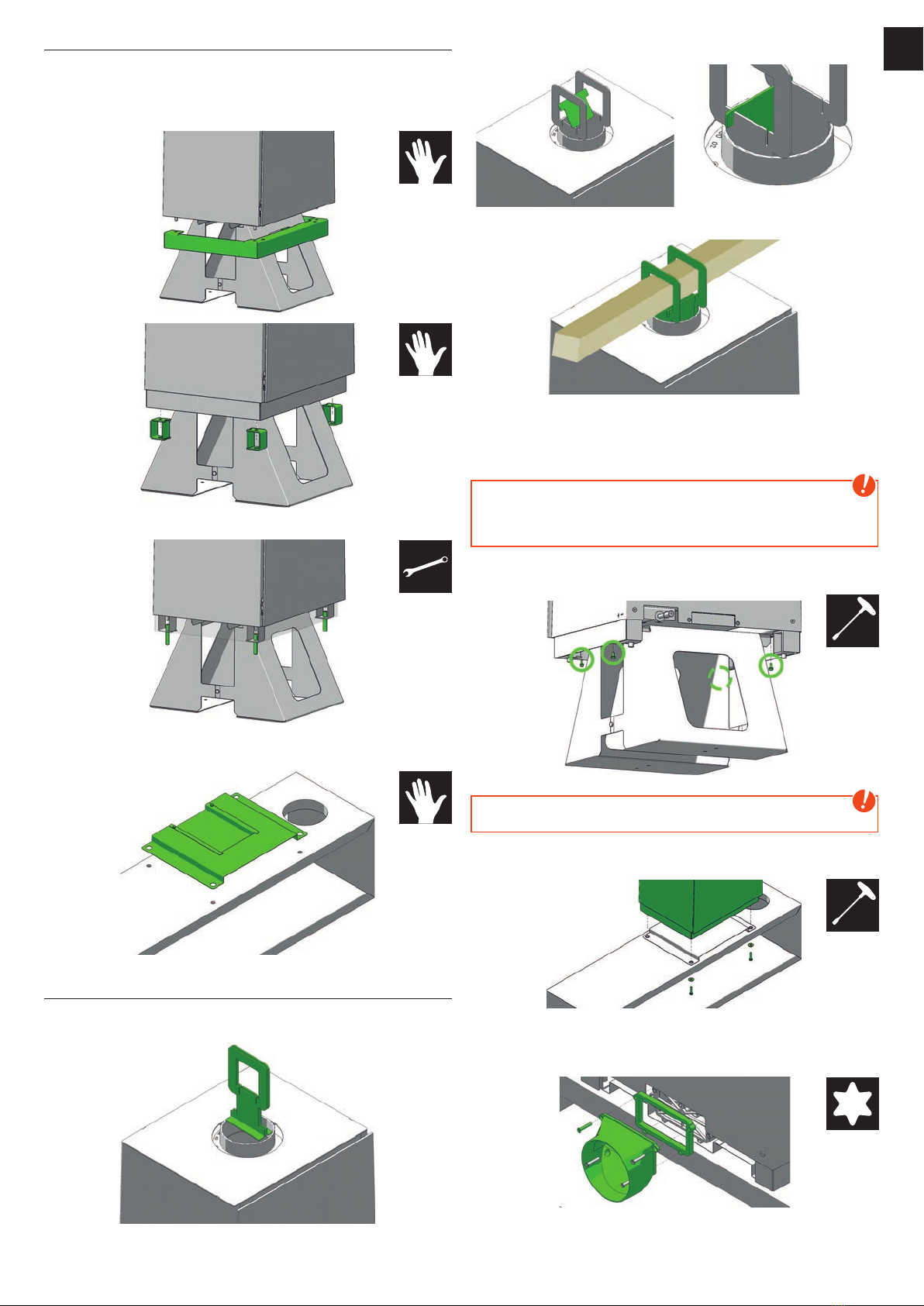
RIKA LOOK RLU User manual

Look RLU
Montageanleitung

2
Zeichenerklärung
...wichtiger Hinweis
#8
...Steckschlüssel
#8 #10
...Gabelschlüssel
#10 ...per Hand
...praktischer Tipp
#10
...Steckschlüssel
#10 #13
...Gabelschlüssel
#13
#25
...Innensechsrund
#25
1. ALLGEMEINES
Varianten Unterbau
1
1
Gussfüße Stahlfüße Holzbank
181
Hinweis
Der Ofen ist mit dem Transportgestell auf der Palette
angeschraubt und damit gegen Umfallen gesichert. Sämtliche
Montagetätigkeiten sollen unbedingt in dieser gesicherten Position
durchgeführt werden!
Tipp
Verwenden Sie die beigelegten Filzgleiter, um Ihren Fußboden zu
schützen!
Hinweis
Fragen Sie Ihren RIKA-Fachhändler nach der RIKA Montagehilfe
E15768. Es wird dringend empfohlen, die Montagehilfe zu benutzen
um den Ofen auf die Holzbank zu stellen.
Hinweis
Bei brennbaren Böden ist immer eine feuerfeste Unterlage
erforderlich, auch vor der Holzbank.
2. HOLZBANK
Lieferumfang E16088
1x Z37306 Sockelblende
1x LB00688
Hitzeschutzblech
1x B17640 Holzsitzbank
1x Z36328 Köcher
1x L03289 Distanz Zuluft
4x Z37307 Distanzhalter
4x Z37308 Gewindehülse
4x N111843
Unterlegscheibe
4x N112214
Sechskantschraube
4x Z33581 Filzgleiter
1x Z36327 Glasscheibe
1x Z36325 Kaminbesteck
Auslieferungszustand

|3
DE
2
Montage
Stellen Sie die Holzbank auf. Die Bohrungen sind symmetrisch, sie
können die Bank mit dem Sitzteil rechts oder links aufstellen.
Stecken Sie zuerst die Sockelblende, danach die 4 Distanzhalter auf
die am Ofen vormontierten Schrauben auf.
Befestigen Sie die Teile mit den beigelegten Gewindehülsen.
Bringen Sie das Hitzeschutzblech auf der Holzbank über den
Bohrlöchern in Position.
Montagehilfe E15768
Die beiden „Henkel“ in den Rauchrohrstutzen oben einführen, so
dass die unteren Kantungen nach außen zeigen.
Nun die beiden Abstandhalter so dazwischenstecken, dass sie mit
den Vorsprüngen in den Schlitzen einrasten.
Durch die Verbindung ist die Position der beiden Henkel fixiert.
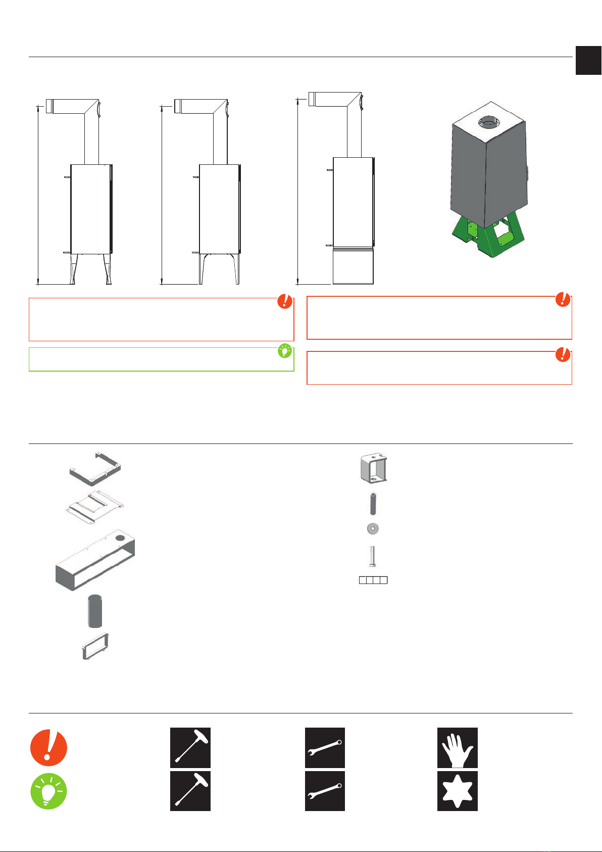
Führen Sie eine stabile Stange oder ein Kantholz durch die beiden
Öffnungen. Der Ofen kann nun angehoben werden. Eine weitere
Person sollte die Führung am unteren Ende des Ofens übernehmen,
um den Ofen in der korrekten Position auf die Holzbank aufzusetzen.
Hinweis
Verwenden Sie keine Rundstäbe oder Rohre, sondern Stangen
mit flacher Auflage. Rutschgefahr! Achten Sie auf gleichzeitiges
Anheben!
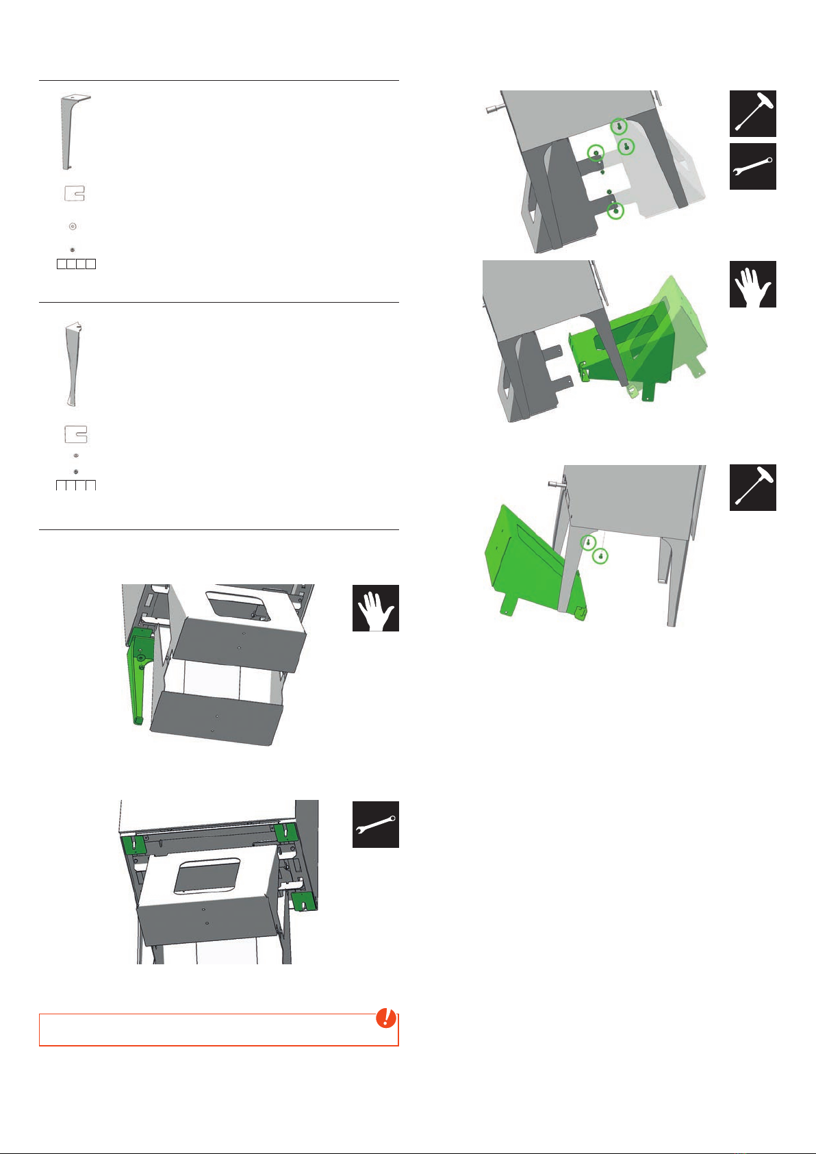
Jetzt lösen Sie nur die Befestigungsschrauben, mit denen die
Transportkonstruktion am Ofen angeschraubt ist.
Hinweis
Achtung, der Ofen ist nicht mehr gesichert, es besteht Kippgefahr!
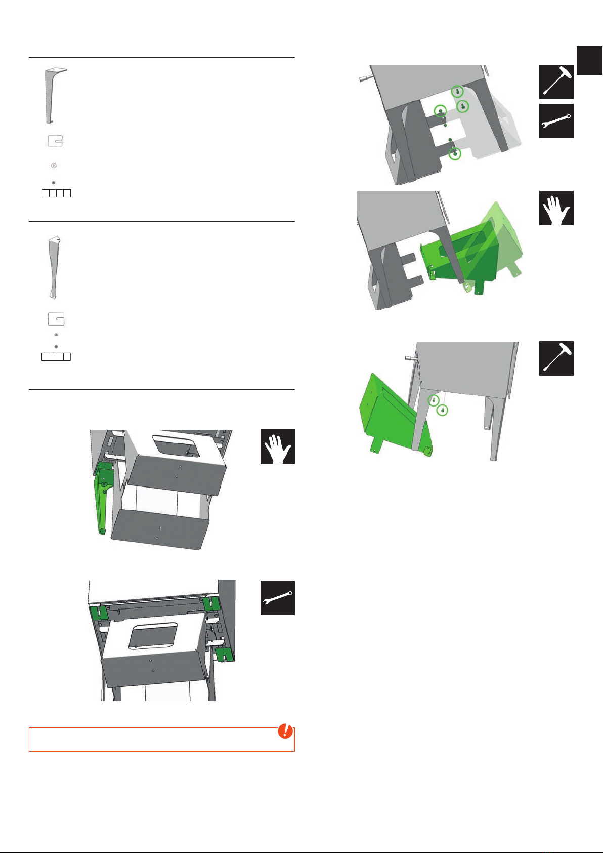
Heben Sie den Ofen vorsichtig auf die Bank, so dass die
Gewindehülsen in die Bohrungen einrasten.
Schrauben Sie die 4 Sechskantschrauben mit Unterlegscheibe
von unten in die Gewindehülsen ein. Der Ofen ist damit gesichert.
Schrauben Sie die Distanz und den Zuluftstutzen an.
Legen Sie die Glasplatte zum Schutz für die Holzoberfläche in das
untere Fach und stellen Sie den Köcher für das Kaminbesteck in die
dafür vorgesehene Bohrung.
#10
#8
#13
#25

4
3. STAHL- UND GUSSFUSS
Lieferumfang E15668 Stahlfuß
4x B17637 Stahlfuß
4x L02763 Einlageblech
4x N111843 Unterlegscheibe
4x N108656 Sechskantmutter
4x Z33581 Filzgleiter
Lieferumfang E 15669 Gussfuß
4x Z36216 Gussfuß
4x L02763 Einlageblech
4x N105049 Unterlegscheibe
4x N108656 Sechskantmutter
4x Z33581 Filzgleiter
Montage
(dargestellt am Beispiel LOOK Stahlfuß)
Befestigen Sie den Stahlfuß und die Einlagebleche mit den Muttern
und Scheiben.
Ziehen Sie die Muttern fest an. Befestigen Sie auf diese Art alle
4 Füße mit den Einlageblechen (Positionen wie unten gezeigt),
Unterlegscheiben und Muttern.
Lösen Sie die Schrauben, mit denen das Transportgestell auf der
Palette befestigt ist.
Hinweis
Achtung, der Ofen ist nicht mehr gesichert, es besteht Kippgefahr!
Kippen Sie den Ofen, z.B. mit Hilfe einer Transportkarre (Sackrodel).
Jetzt schrauben Sie eine Seite der Transportkonstruktion ab.
Nun kippen Sie den Ofen auf die freistehenden Füße und schrauben
den zweiten Teil der Transportkonstruktion ab.
Stellen Sie den Ofen vorsichtig auf alle 4 Füße.
#13
#8
#10
#8

Technische und optische Änderungen, sowie Satz- und Druckfehler vorbehalten
© 2017 | RIKA Innovative Ofentechnik GmbH
Z37440_Look_RLU_Montage_DE_FR_IT_EN_NL | 8.05.2017
RIKA Innovative Ofentechnik GmbH
Müllerviertel 20
4563 Micheldorf / AUSTRIA
Tel.: +43 (0)7582/686
- 41, Fax: -43
E-Mail: verkauf@rika.at www.rika.at

6
Look RLU
Notice de montage

|7
FR
6
Explication des symboles
...Information
importantes #8
...Tournevis
hexagonal #8 #10
...Clef à la
fourche #10 ...à la main
...Conseil pratique
#10
...Tournevis
hexagonal #10 #13
...Clef à la
fourche #13
#25
...Clef pour vis
étoile #25
1. GÉNÉRALITÉS
Variantes de piètements
1
1
181
Pieds en fonte Pieds en acier Banc en bois
Attention
Le poêle est vissé avec le châssis de transport sur la palette afin
d’éviter les risques de chute. Toutes les opérations de montage
doivent impérativement être réalisées dans cette position assurée!
Conseil
Utilisez les patins en feutre pour protéger votre sol !
Attention
Demandez le dispositif d’aide au montage E15768 auprès de votre
revendeur RIKA. Il est vivement recommandé d’utiliser le dispositif
d’aide au montage pour l’installation du poêle sur le banc en bois.
Attention
En cas de sol inflammable, un support ignifuge doit impérativement
être installé, aussi devant le banc en bois.
2. BANC EN BOIS
Eléments fournis E16088
1x Z37306 Cache de socle
1x LB00688 Bouclier
thermique
1x B17640 Banc en bois
1x Z36328 Serviteur
1x L03289 Distance pour
tuyau d‘aspiration
4x Z37307 Entretoise
4x Z37308 Manchon fileté
4x N111843 Rondelle
4x N112214 Vis à tête
hexagonale
4x Z33581 Patin en feutre
1x Z36327 Vitre
1x Z36325 Accessoires
État à la livraison du poêle

8
Montage
Installez le banc en bois. Les trous sont symétriques et permettent
de monter le banc avec le siège à gauche ou à droite.
Posez d’abord le cache de socle, puis les 4 entretoises sur les vis
prémontées sur le poêle.
Fixez les pièces à l’aide des manchons filetés joints.
Placez le bouclier thermique sur le banc en alignant les trous.
Dispositif d’aide au montage E15768
Insérez les deux « anses » dans le raccord du conduit de fumée de
sorte que les bords inférieurs soient orientés vers l’extérieur.
Installez ensuite les cales d’espacement de sorte que les saillies
s’insèrent dans les fentes.
La position des deux anses est bloquée par cet assemblage.
Passez une barre stable ou une pièce de bois équarri par les deux
ouvertures. Le poêle peut alors être soulevé. Une autre personne
doit tenir le bas du poêle afin de guider la manœuvre et assurer son
installation correcte sur le banc en bois.
Attention
N’utilisez pas de barres rondes ou de tubes, mais uniquement des
barres à surface plane. Risque de glissement ! Veillez à lever le
poêle simultanément !
Desserrez ensuite les vis fixant le châssis de transport au poêle.
Attention
Prudence : le poêle n’est plus fixé, risque de basculement !
Levez le poêle et posez-le avec précaution sur le banc de sorte que
les manchons filetés s’insèrent dans les trous.
Vissez les 4 vis à tête hexagonale avec une rondelle dans les
manchons filetés par-dessous. Le poêle est alors fixé. Vissez le tuyau
d‘aspiration avec la distance.
Posez la vitre de protection de surface du bois dans le compartiment
inférieur et placez le serviteur pour les accessoires dans l’orifice
prévu à cet effet.
#10
#8
#13
#25

|9
FR
8
3. PIEDS EN ACIER ET EN FONTE
Eléments fournis E15668 Pieds en acier
4x B17637 Pied en acier noir
4x L02763 Cale
4x N111843 Rondelle
4x N108656 Écrou six pans
4x Z33581 Patin en feutre
Eléments fournis E 15669 Pieds en fonte
4x Z36216 Pied en fonte
4x L02763 Cale
4x N105049 Rondelle
4x N108656 Écrou six pans
4x Z33581 Patin en feutre
Montage
(Illustration avec exemple LOOK avec des pieds en acier)
Fixez un premier pied en acier avec une cale au moyen d’un écrou
et d’une rondelle.
Serrez l’écrou à fond. Montez de cette manière les 4 pieds avec une
cale (positions indiquées ci-dessous).
Desserrez les vis fixant le châssis de transport à la palette.
Attention
Prudence : le poêle n’est plus fixé, risque de basculement !
Basculez le poêle, par exemple à l’aide d’un chariot de transport
(diable). Dévissez un côté du châssis de transport.
Basculez ensuite le poêle sur les pieds dégagés et dévissez le second
côté du châssis de transport.
Dressez le poêle sur ses 4 pieds avec précaution.
#13
#8
#10
#8

Sous réserve de modifications techniques et visuelles et d´erreurs de
composition et d´impression.
© 2017 | RIKA Innovative Ofentechnik GmbH
Z37440_Look_RLU_Montage_DE_FR_IT_EN_NL | 8.05.2017
RIKA Innovative Ofentechnik GmbH
Müllerviertel 20
4563 Micheldorf / AUSTRIA
Tel.: +43 (0)7582/686 - 41, Fax: -43
E-Mail: verkauf@rika.at www.rika.at

Look RLU
Istruzioni per montaggio

12
Spiegazione dei simboli
...Informazione
importante #8
...Esagonale #8
#10
...Chiave a
bocca #10 ...Manualmente
...Consigli pratici
#10
...Esagonale #10
#13
...Chiave a
bocca #13
#25
...Vite a stella #25
1. INTRODUZIONE
Tipi di basamenti
1
1
Piedino in ghisa Piedino in acciaio Panchina in legno
181
Attenzione
La stufa è fissata con la gabbia di trasporto sul pallet, il che
impedisce un’eventuale caduta della stufa. Tutte le attività di
montaggio vanno effettuate in questa posizione di sicurezza!
Consiglio
Utilizzare i feltrini per proteggere il vostro pavimento da eventuali
danni.
Attenzione
Chiedete al vostro rivenditore RIKA il kit montaggio E15768. Si
raccomanda vivamente l’utilizzo del kit montaggio per installare
la stufa sulla panchina.
Attenzione
In caso di pavimentazioni infiammabili è necessario predisporre
una base di appoggio (vetro, lamiera di acciaio o ceramica) sotto
la stufa, anche davanti alla panchina.
2. PANCHINA IN LEGNO
Articoli consegnati E16088
1x Z37306 Frontalino
basamento
1x LB00688 Lamiera
anticalore
1x B17640 Panchina in
legno
1x Z36328 Contenitore set
pulizia camino
1x L03289 Distanziatore
per ingresso aria
4x Z37307 Distanziatore
4x Z37308 Bussola filettata
4x N111843 Rondella
4x N112214 Vite esagonale
4x Z33581 Feltrino
1xZ36327 Piastra in vetro
1xZ36325 Set pulizia
camino
Stato della stufa al momento
della consegna

|13
IT
12
Montaggio
Appoggiare la panchina in legno. I fori sono simmetrici, potete girare
la panchina e installarla con la parte del sedile a destra o sinistra.
Fissare per prima cosa il frontalino e poi i 4 distanziatori sulle viti
premontati sulla stufa.
Fissare i pezzi con le bussole filettate.
Posizionare la lamiera anticalore sulla panchina appoggiandola sui
fori.
Kit montaggio E15768
Inserire i due ganci nel raccordo tubi superiore, con le lamiere
inferiori verso la parte esterna.
Inserire adesso in mezzo tra i due ganci i distanziatori, badendo al
corretto inserimento nella sede prevista.
Grazie alla connessione tra di loro, la posizione dei due ganci
rimane ben fissata.
Far passare una barra di metallo oppure un travetto in legno
dalle due aperture. Ora è possibile alzare la stufa. Si consiglia
che una altra persona controlli bene i movimenti del lato inferiore
della stufa, per poterla appoggiare sulla posizione corretta sui
basamenti.
Attenzione
Non utilizzare barre rotonde oppure tubi, utilizzare esclusivamente
barre con appoggio piano. Rischio di scivolamento! Fare attenzione
ad alzare la barra su entrambi i lati nello stesso momento!
Togliere le viti di fissaggio tra struttura di trasporto e stufa.
Attenzione
Attenzione, la stufa non è più fissata, pericolo di caduta!
Alzare la stufa con cautela sulla panchina, inserendo bene le bussole
filettate nei fori.
Inserire le viti esagonali con la rondella dalla parte inferiore nelle
bussole filettate. La stufa è quindi messa in sicurezza. Fissare il
distanziatore e l‘ingresso aria.
Appoggiare la piastra in vetro per proteggere la superficie del
legno, inserendola nella parte inferiore della panchina a legno.
Inserire il contenitore nel foro predisposto.
#10
#8
#13
#25

14
3. PIEDINI IN GHISA E ACCIAIO
Articoli consegnati E15668 Piedini in ghisa
4x B17637 Piedino in acciaio
4x L02763 Lamiera di fissaggio
4x N111843 Rondella
4x N108656 Dado
4x Z33581 Feltrino
Articoli consegnati E 15669 Piedini in
acciaio
4x Z36216 Piedino in acciaio
4x L02763 Lamiera di fissaggio
4x N105049 Rondella
4x N108656 Dado
4x Z33581 Feltrino
Montaggio
(esempio LOOK con piedino in acciaio)
Fissare il piedino in acciaio e la lamiera di fissaggio con i dadi e le
rondelle.
Fissare bene i dadi. Procedere nella stessa maniera tutti i 4
piedini con la lamiera di fissaggio (posizione come da immagine
sottostante), le rondelle ed i dadi.
Togliere le viti di fissaggio tra struttura di trasporto e bancale.
Attenzione
Attenzione, la stufa non è più fissata, pericolo di caduta!
Inclinare la stufa, ad esempio con l’aiuto di un carrello per il trasporto.
Ora svitare un lato della struttura per il trasporto.
Appoggiare ora la stufa sui piedini e svitare il secondo lato della
struttura per il trasporto.
Appoggiare la stufa con cautela su tutti i 4 i piedini.
#13
#8
#10
#8

Con riserva di modifiche tecniche e visive, come anche di errori di stampa e composizione.
© 2017 | RIKA Innovative Ofentechnik GmbH
Z37440_Look_RLU_Montage_DE_FR_IT_EN_NL | 8.05.2017
RIKA Innovative Ofentechnik GmbH
Müllerviertel 20
4563 Micheldorf / AUSTRIA
Tel.: +43 (0)7582/686
- 41, Fax: -43
E-Mail: verkauf@rika.at www.rika.at

Look RLU
Assembly manual
16

|17
EN
16
Explanations to symbols
...Important note
#8
...Hex #8
#10
...Open-end
wrench #10 ...Manually
...Useful tip
#10
...Hex #10
#13
...Open-end
wrench #13
#25
...Hexalobular
T25
1. PREFACE
Different basements
1
1
181
as oo eel oo ooden ench
Note
The stove is screwed with the transport construction on the pallet
to secure it against falling. All assembly operations have to be
carried out in this secured position!
Tip
Use the enclosed felt gliders to protect your floor!
Note
It is strongly recommended to use the “RIKA installation kit E15768”
for installation. Ask your local RIKA-dealer for it.
Note
A base is required (glass, sheet steel or ceramic) in front of the
stove if the floor is combustible. This is also valid for wooden bench.
2. WOODEN BENCH
Delivered Parts E16088
1x Z37306 Plinth panel
1x LB00688 Heat shield
1x B17640 Wooden bench
1x Z36328 Fire iron quiver
1x L03289 Distance for air
intake socket
4x Z37307 Spacer
4x Z37308 Threaded
sleeve
4x N111843 Washer
4x N112214 Hexagonal bolt
4x Z33581 Felt glider
1x Z36327 Glass plate
1x Z36325 Fire irons
Delivery state stove

18
Mounting
Set the wooden bench as desired. The holes are symmetrical, you
can turn around the bench and set the seat part right or left.
First, plug the plinth panel, then the 4 spacers on the preassembled
screws on the stove.
Fasten the parts with the enclosed threaded sleeves.
Lay the heat shield on the wooden bench, hole on hole.
Mounting support E15768
Insert the two „handles“ in the top flue outlet so that the lower
bending faces outward.
Now insert the two spacers between them so that they engage with
the tabs into the slots.
Now the position of the two handles is fixed.
Put a stable rod or a square timber through the two openings. The
stove can now be lifted. A third person should lead the bottom of
the stove to find the correct position on the basement.
Note
Do not use round rods or tubes, only rods with a flat contact
surface. Risk of slipping! Pay attention to the simultaneous lifting.
Now unscrew the transportation construction from the stove.
Note
Warning, the stove is no longer secured against tipping!
Lift the stove careful and set it on the bench with the threaded
sleeves into the holes.
Screw the hexagonal bolts and washers from the bottom into the
threaded sleeves. The stove is now secured. Attach the air intake
socket and the distance.
Insert the glass plate in the lower shelf to protect the wooden
surface. Put the quiver for the fire irons into the provided hole.
#10
#8
#13
#25

|19
EN
18
3. STEEL- AND CAST CASE LEGS
Delivered Parts E15668 Steel leg
4x B17637 Steel leg
4x L02763 Insert plate
4x N111843 Washer
4x N108656 Hexagonal nut
4x Z33581 Felt glider
Delivered Parts E 15669 Cast iron leg
4x Z36216 Cast iron foot
4x L02763 Insert plate
4x N105049 Washer
4x N108656 Hexagonal nut
4x Z33581 Felt glider
Mounting
(exemplified by LOOK with steel leg)
Attach the steel leg and the insert plate with the nut and washer.
Tighten the nut firmly. Attach all 4 legs in this way with the insert
plates (positions as shown below), washers and nuts.
Loosen the screws which are holding the transport frame to the
pallet.
Note
Warning, the stove is no longer secured against tipping!
Tilt the stove, for example with a transport trolley. Now unscrew one
side of the transport frame.
Now tilt the stove on the free-standing feet and unscrew the second
part of transportation frame.
Set the stove carefully on all 4 feet.
#13
#8
#10
#8

Technical and design changes, as well as typesetting and printing errors reserved
© 2017 | RIKA Innovative Ofentechnik GmbH
Z37440_Look_RLU_Montage_DE_FR_IT_EN_NL | 8.05.2017
RIKA Innovative Ofentechnik GmbH
Müllerviertel 20
4563 Micheldorf / AUSTRIA
Tel.: +43 (0)7582/686 - 41, Fax: -43
E-Mail: verkauf@rika.at www.rika.at
Other manuals for LOOK RLU
2
This manual suits for next models
3
Table of contents
Languages:
Other RIKA Stove manuals
Popular Stove manuals by other brands

SCAN
SCAN Andersen 4-5 Instructions for installation and use

ACR STOVES
ACR STOVES MV2CL Technical manual

Campingaz
Campingaz CAMP'BISTRO XL STOPGAZ Instructions for use

LAMINOX
LAMINOX IDRO Hot Spot 13 Wind Use and maintenance instructions

Palazzetti
Palazzetti TERMOPALEX 78 FAST PRODUCT TECHNICAL DETAILS

Heta
Heta SCAN-LINE GREEN 300 Operating and installation instructions