Rinnai CNTRLDRCIPB Quick start guide

Deluxe wired remote controllers
Operation and installation guide
26.5°C
AM
0
1
5
8
:
.5
°C
2
6
MODELS
CNTRLDRCIPB / CNTRLDRCIPW

Important
Controller must be installed in accordance with:
- Manufacturer’s installation instructions
- Current AS/NZS 3000, AS/NZS 5141, AS/NZS 5419,
AS/NZS 1677, and AS/NZS 60335.2.40
- HB276 - A Guide to good practice for energy ecient installation
Must be installed, maintained and removed only by an authorised
person.
Warning
Improper installation, adjustment, alteration, service and maintenance
can cause property damage, personal injury or loss of life.
For more information about buying, using, and servicing of Rinnai
appliances call: 0800 RINNAI (0800 746 624).

Contents
Safety and important information........................................
Installation ..........................................................................
Controller operation
LCD Display........................................................................
Controller buttons ...............................................................
Operation............................................................................
Special functions setting.....................................................
Fault codes.........................................................................
Wi-Fi control .......................................................................
Wi-Fi registration and connection.......................................
4
5
12
13
14
20
27
28
29

4|
Safety and important information
DO NOT install the controller in a place exposed to leakage or
ammable gases. Once ammable gases are leaked and left
around the controller, re may occur.
DO NOT operate with wet hands or let water enter the wired
controller—electric shock may occur.
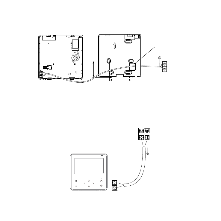
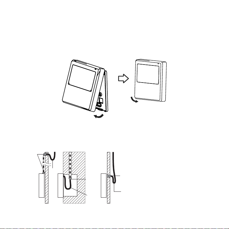
Controller must be wired according to the wiring diagram.
The wired controller operates in a low voltage loop circuit, DO NOT
contact the cable to 220-240 V power.
The shielded wire of the wired controller MUST BE grounded.
After completing the wired controller connection, DO NOT use a
megger tester to check the insulation. This may damage the product.
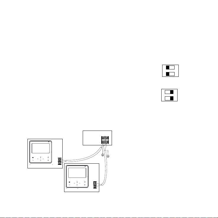
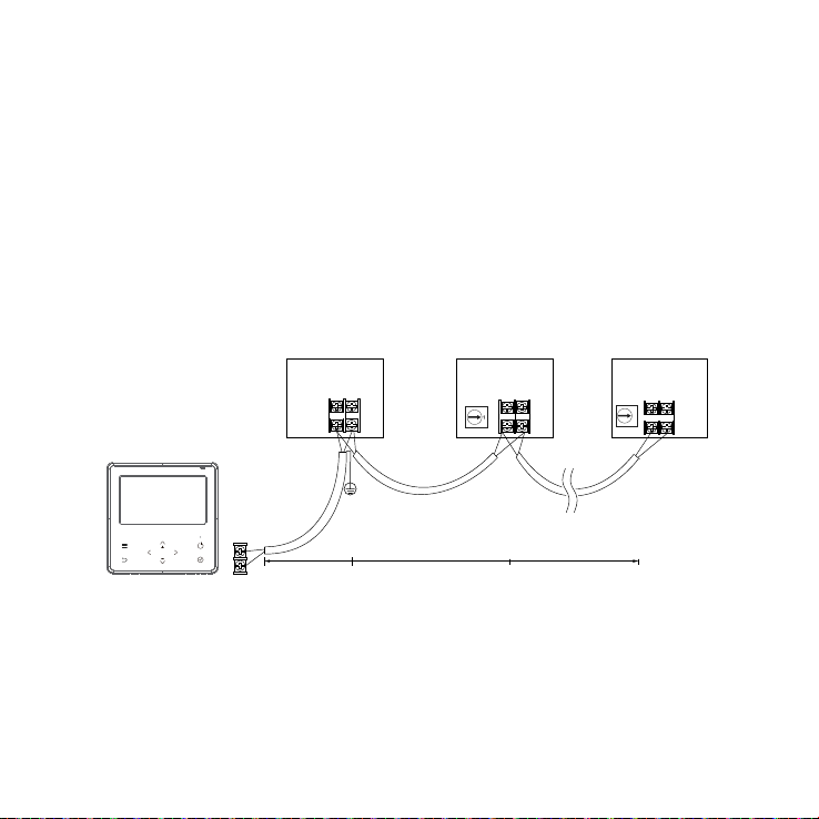
A maximum of TWO CONTROLLERS may be installed on a system.
Specication
Input voltage: DC 5 V / DC 12 V
Ambient temperature.: 0~43 °C
Ambient humidity: 40-90% RH
Controller loom shall be 2-core (0.5 mm2) shielded cable, up to 40 m.

| 5
Installation
Backing plate
Remove the backing plate by inserting
a at screwdriver in the lower part of the
controller, rotate (do not pry up and down) to
remove the backing plate.
The PCB is mounted in the upper part of the
controller, be careful not to damage.
Fasten the backing plate on the wall with three
screws (ST3.9*25) and plugs (provided).
120 mm
120 mm
20 mm
60 mm
46 mm
44 mm
84 mm 19 mm
Screwdriver
locations
Backing
plate

6|
Loom access point
Remove plastic knockout from the backing plate.
Create a hole in the wall to access the wall cavity
for routing the loom from the indoor unit to the
controller.
Put on a at surface. Be careful not to distort the
back plate by over tightening the mounting screws.
Battery installation (CR2032)
Keep batteries out of reach of children.
Swallowing may lead to serious injury
in as little as two hours, or death due to
chemical burns and potential perforation of
the oesophagus.
Slide the battery into the holder with the positive side facing up.
When rst turning on set up the time of day. If the system is exposed
to a power outage the battery will maintain the time of day. If the
displayed time is not correct once power is restored try replacing the
battery.
Remove
knockout
WARNING

| 7
Thermostat connection to the indoor unit
44 mm
Indoor unit
PCB
60 mm
Loom
knockout
HA
HB
Indoor unit
Connect the terminals on the wired controller (HA, HB), and the
terminals on the indoor unit (HA, HB). There is no polarity between HA
and HB, refer image below.
HB
Indoor unit
Wired controller
HA
HB
HA HB

8|
HA HB
Indoor unit
Earth the
shielded
wire
Max. 40 m
Max. 40 m
Controller 1
Controller 2
HA
HA
HB
HB
Setting up two controllers
Up to two controllers can be connected to the HA and HB terminals on
the indoor unit as shown.
From the factory all controllers are supplied with SW1
dip switch setting 1 OFF and dip switch setting 2
OFF. When conguring a second controller, two dip
switches on the rear of the second controller (SW1
location) must change to the ON position as shown.
Dip switch settings for the primary controller must
remain unchanged.
If two controllers are installed both are equal and
reect the same information, and operational changes can be done on
either controller. Wi-Fi control may be setup on one of the controllers
only. There is no polarity between HA and HB.
Controller 1 (primary)
SW1
1 2
ON
Controller 2 (secondary)
SW1
1 2
ON

| 9
Controller 1
Total length 40 m maximum
Indoor unit 1 Indoor unit 2 Indoor unit n
Max. 16
HA
HA HA HA HB
HB
HB
HB
2
One controller to multiple units
For some units, one wired controller can support multiple units (a
maximum of 16).
For conguration of multiple indoor units loom connection is polarity
sensitive and HA must connect to HA on all indoor units, the same
applies to HB. In group control there will be no error displayed on the
wired controller.

10 |
Reattach backing plate of the wired controller
To reconnect the fascia to the back plate, anchor the top lugs rst as
shown below then swing the fascia down and press lightly to engage
the bottom tabs. Be careful not to pinch the loom during the process.
DO NOT allow water to enter the controller, use trap and putty to seal
the connectors. Connecting wires must be securely xed in place.
Putty
Putty Putty
Trap
Trap Trap

Controller operation
Functions
• Mode: Auto-Cool-Dry-Heat-Fan
• Fan speed: Auto/Low/Med/High
• Timer ON/OFF
• Temperature setting
• Weekly timer
• Follow me
• Turbo
• Child lock
• Clock

12 |
LCD display
FAN SPEED display
Displays selected fan
speed:
LOW
MED
HIGH
TURBO
AUTO
Room temperature
Follow me
ECO
Wireless control
Active clean
Delay off
SLEEP
Filter cleaning reminder
Choose
Timer settings
Timer
Function
Mode
Child lock
Temperature
Warning
Set up
Vertical louver swing
Horizontal louver swing
26.5°C %66
AM
0
1
5
8
:
.5
°C
2
6
Time Status Bar
Navigation Bar
Function display
MODE display
Displays the current
mode,including:
AUTO COOL DRY HEAT FAN

| 13
Controller buttons
Menu
Return
Left / Right / Up / Down
Enter
ON/OFF

14 |
Operation
To start press the power button on the controller. The main page
display will appear.
Power-on status
main page display
Shutdown status
main page display
AM
0
1
5
8
:
.5
°C
2
6
26 .5°C %66
O
AM
,
0
1
5
8
:
Sun,
Nov
1
9
.
26 .5°C %66
AM
0
1
5
8
:
.5
°C
2
6
O
AM
,
0
1
5
8
:
Sun,
Nov
1
9
.
Power-on status
main page display
Shutdown status
main page display

| 15
Standby and screen o
Standby occurs after 30 seconds if no button is pressed. After entering
the standby state, the controller exits all setting states and restores the
main page display.
Screen o occurs after 60 seconds if no button is pressed. Press any
key to return to the home page screen.
°C
0
26
5
2
6
.
°C
6
6
%
AM
,
0
1
5
8
:
Sun,
Nov
1
9
.

16 |
Date and time setting
The lower section of date and time setting can be set to 12/24 hour
system switching, wired controller time setting or wired controller date
setting.
24-Hour Time
Timer Setting
Date Setting
Date & Time Setting
09:00
Nov-17-2021
The time, and date setting interface on the wired controller is as
follows:
0
8
0
0
A
M
Timer On
NOV 10 2021
Date Setting
°C / °F setting
Press the up and down buttons for three seconds will alternate the
display between °C and °F.

| 17
Mode setting (M)
1. Press the left or right buttons to select ‘Mode’.
2. Press the up or down buttons to select the mode of operation and
press the enter button (tick) to adjust the settings.
If Auto or Dry mode is selected, the fan speed is xed and cannot
be adjusted—the set temperature is adjustable.
If Cool or Heat mode is selected, the fan speed and temperature
can be adjusted.
When in Fan mode, the temperature display will be greyed out, the
temperature cannot be adjusted.
Set temperature setting
Press the up or down buttons to set the room temperature. Setting
temperature range 10/16/17~30 °C or 20~28 °C (model dependent).

18 |
Fan speed setting
Press the left or right buttons to select ‘Fan’. Fan speed is unavailable
in ‘Auto’ or ‘Dry’ modes. Press the up or down buttons to select the fan
speed and then press enter (tick) to change the fan speed.
Press the up or down buttons to select customised fan speed, then
press enter (tick) to enter stepless fan speed. In stepless fan speed
press the up or down buttons to adjust. The range is 1~100%. Press
return to exit.
AM
0
1
5
8
:
High
Med
Low
Auto
Fan Speed
5
0
%

| 19
Fan direction setting (model dependent)
Press the left or right buttons to select louver swing.
AM
0
1
5
8
:
Vertical Louver Swing
Horizontal Louver Swing
Press the up or down buttons to select the fan direction function, press
enter (tick) to enable or disable the function.
When the horizontal louver swing is selected, press enter (tick) to
enable/disable the horizontal swing function.
When the vertical louver swing is selected, press enter (tick) to enable/
disable the vertical swing function.
66 %C°5.62
AM
0
1
5
8
:
2
6
.5
°C
%
58

20 |
Turbo
This mode allows you to cool indoor air quickly in summer or warm
it quickly in winter. In turbo mode the fan is set to operate at the
maximum output.
Menu > up or down buttons > function icon > enter > turbo turn on
The turbo wind speed icon on the home page is displayed.
Special function settings
Follow me
When follow me is activated the room temperature is detected at the
sensor in the wired controller. When follow me is not active the room
temperature is detected at the air inlet of the indoor unit.
Menu -> up or down buttons -> function icon -> enter -> follow me. The
follow me icon on the home page is displayed.
This manual suits for next models
1
Table of contents
Other Rinnai Remote Control manuals
Popular Remote Control manuals by other brands

AERTECNICA
AERTECNICA TUBO CM837 instructions

Reely
Reely 2139582 operating instructions

Philips
Philips SRU9400/17 Instructions for use

Hard Head
Hard Head 007591 operating instructions

Universal Remote
Universal Remote Genesis MX-900 brochure

Mitsubishi Electric
Mitsubishi Electric PAR-SL101A-E Series Operation manual and installation manual