Rion NL-62 User manual

Sound Level Meter
NL-62
Quick Instruction Manual
(Ver.1.0)
RION CO., LTD.
Technical Support Division,
Sound and Vibration Measuring Instruments Business Department
November 9th, 2012
HU0-01
Sound Level Meter
(With low-frequency sound measurement function)
Class 1 NL-62

1
Contents
1 Controls and Functions...................................................................................................................................... 3
1-1. Front panel, Operation key panel.............................................................................................................. 3
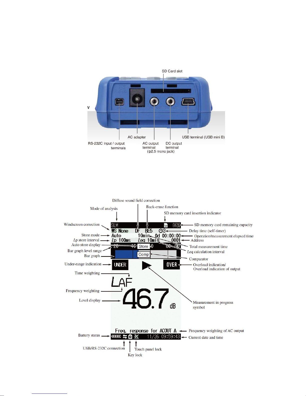
1-2. Input/Output Connectors........................................................................................................................... 4
1-3. Measurement screen display..................................................................................................................... 4
2. Preparations...................................................................................................................................................... 5
2-1. Power on/off.............................................................................................................................................. 5
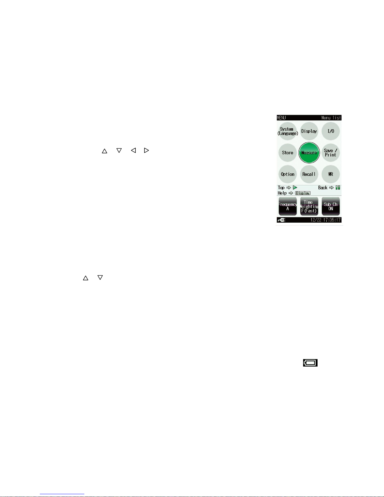
2-2. Menu list screen........................................................................................................................................ 5
2-3. Battery type............................................................................................................................................... 5
2-4. Battery status............................................................................................................................................. 5
2-5. Output level range..................................................................................................................................... 5
2-6. Internal calibration.................................................................................................................................... 7
2-7. Acoustic calibration .................................................................................................................................. 7
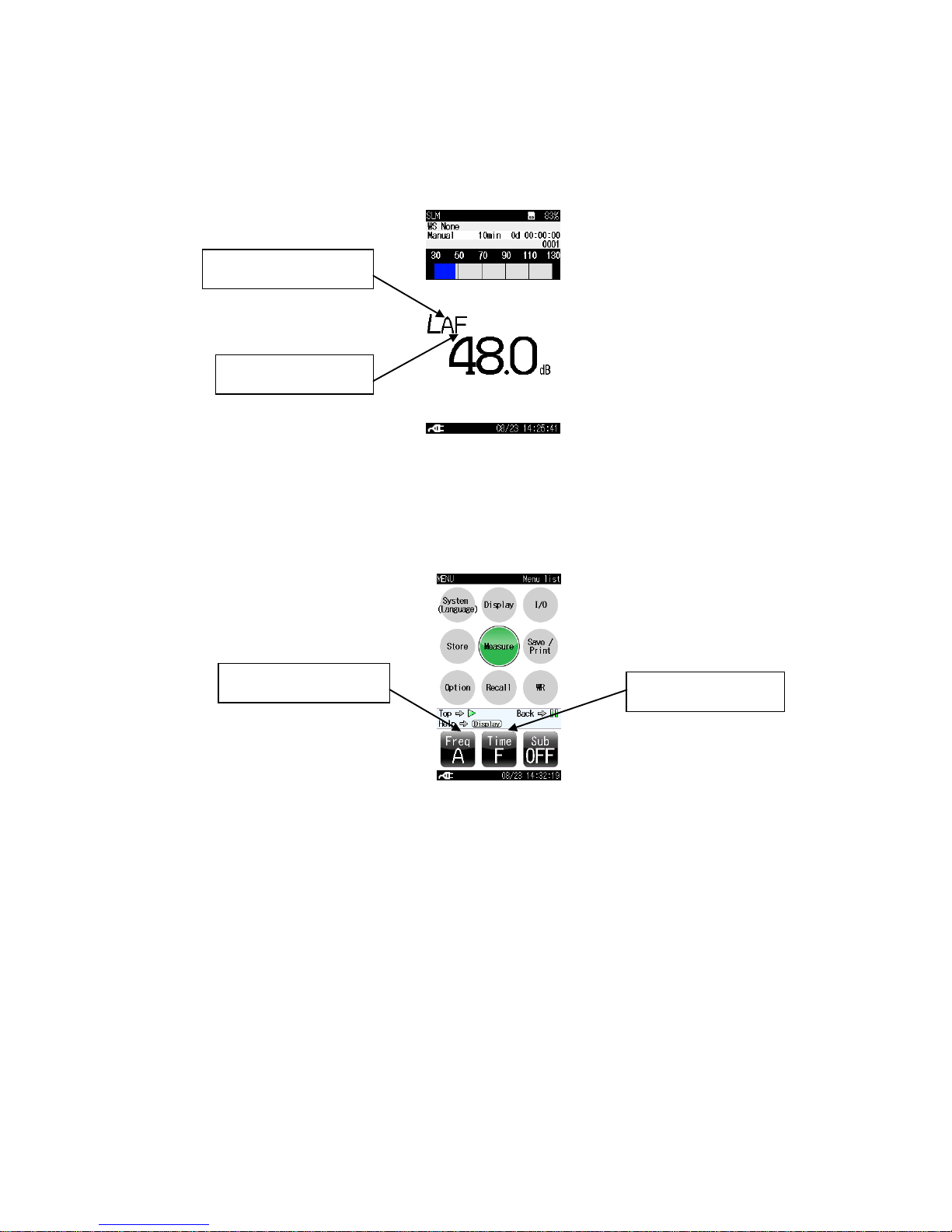
2-8. Setting of the frequency weighting and the time weighting...................................................................... 9
3. Measurement.................................................................................................................................................. 10
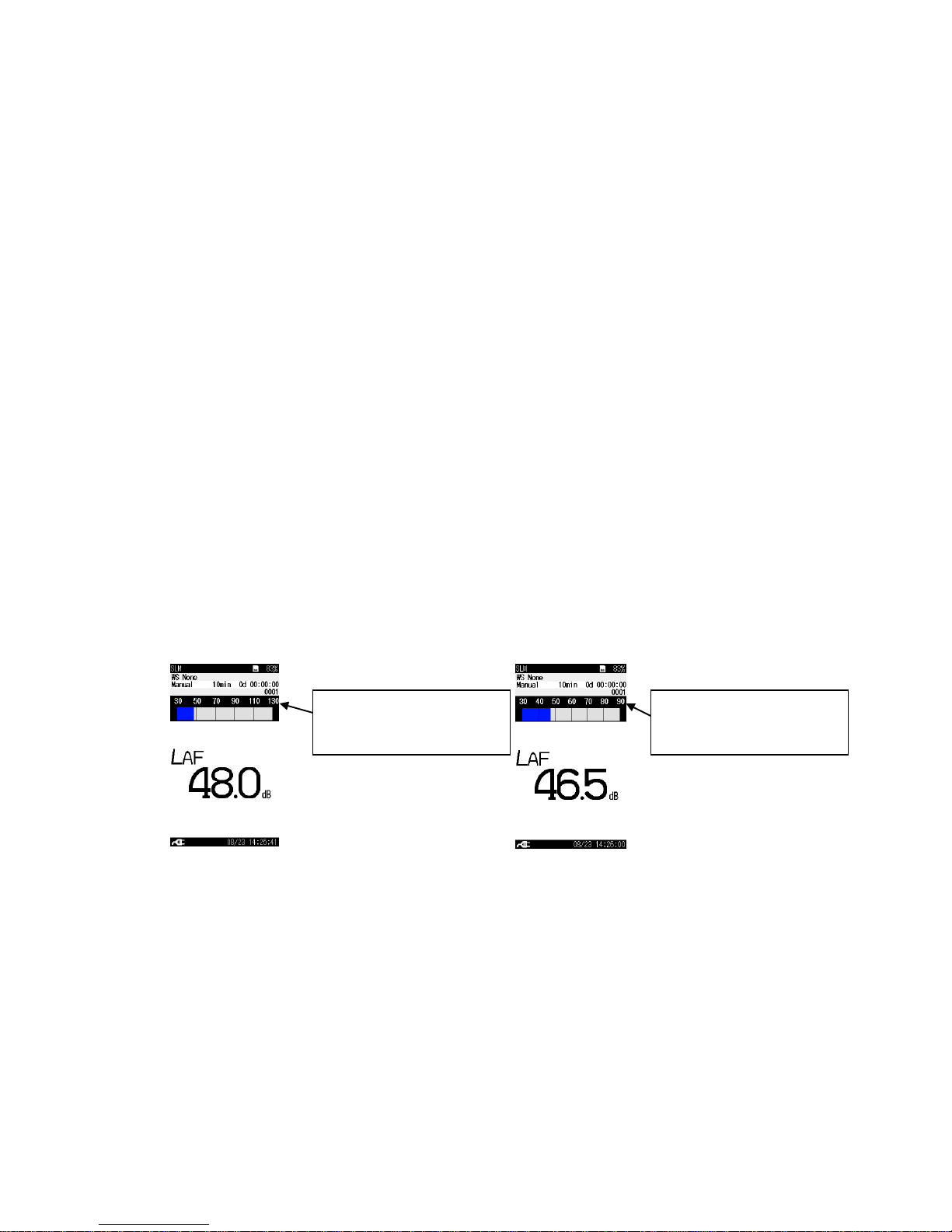
3-1. Sound level measurement ....................................................................................................................... 10
3-2. Store operation.........................................................................................................................................11
(1) Manual mode operation...........................................................................................................................11
(2) Auto mode operation .............................................................................................................................. 14
(3) Timer Auto mode operation.................................................................................................................... 17
4. Data recall ...................................................................................................................................................... 20
4-1. Recalling stored data on sound level meter............................................................................................. 20
4-2. Recalling stored data on a computer....................................................................................................... 22
5. Delay time, Pause, Back erase........................................................................................................................ 25
5-1. Delay time............................................................................................................................................... 25
5-2. Pause, Back erase.................................................................................................................................... 26
6. Marker............................................................................................................................................................ 28
7. Sub channel settings, Additional processing settings..................................................................................... 29
8. Waveform recording....................................................................................................................................... 31
8-1. Manual recording.................................................................................................................................... 34
8-2. Level recording....................................................................................................................................... 35
8-3. Interval recording.................................................................................................................................... 37
8-4. Total recording........................................................................................................................................ 38
9. Other operations ............................................................................................................................................. 39
9-1. Stored data copy to a computer connected via USB ............................................................................... 39
9-2. Data recovery.......................................................................................................................................... 39
9-3. Screen hard copy..................................................................................................................................... 39

2
9-4. Key lock.................................................................................................................................................. 40
9-5. Eco setting (Power-saving mode) ........................................................................................................... 40
10. Menu list....................................................................................................................................................... 41
10-1. Menu list items of NL-62...................................................................................................................... 41
10-2. Menu list items of NX-42WR............................................................................................................... 41

3
1.Controls and Functions
1-1.Front panel, Operation key panel
This sound level meter has the following display and key panel.
Several settings such as frequency weighting, time weighting and other parameters for measurement are set
from the menu list.
The display supports various languages, and enables user-friendly, intuitive operation designed to be used
comfortably, also by persons who are inexperienced in measurements.
Display
POWER key
Turns power to the unit on and off.
Indicator LED
Lights/fashes in red or blue
to indicate the operation or
status of the unit.
PAUSE/CONT key
Press the key to pause
measurement, and press the key
again to resume measurement.
CAL key
This key is used for calibration of
the unit and for level calibration of
connected equipment.
DISPLAY key
This key switches measurement
screen display.
LIGHT key
This key turns on the display
backlight. Press the key again to
turn the backlight off.
START/STOP key
Press to start or stop the measurement
MENU/ENTER key
Press this key to make or finalize the setting
of an item in a menu or any other setting.
When the key is pressed at the measurement
screen, the menu list screen comes up.
Microphone
Preamplifier
Bottom cover
This cover protects the connectors on
the bottom during transport or storage.
Removing the cover gives access to the
connectors.
key
These four keys serve for selecting
and setting items on menu screens.

4
1-2.Input/Output Connectors
A variety of I/O connections
1-3.Measurement screen display
The illustration below shows all elements of the display for explanation purposes.
In actual operation, such a screen will not be shown.

5
2.Preparations
2-1.Power on/off
Power on : Hold down the POWER key until the power-on screen appears (at least 1 second).
Power off : Hold down the POWER key until the unit is turned off (several seconds).
2-2.Menu list screen
①When the measurement screen is displayed, pressing the MENU/ENTER
key brings up the menu list screen as shown to the right.
②Use the / / / keys to select the desired menu item and press
the MENU/ENTER key.
③Pressing the DISPLAY key displays explanation (help) screen of the item
that has been selected.
④Pressing the PAUSE/CONT key switches back to the previous screen.
⑤Pressing the START/STOP key switches back to the measurement screen.
2-3.Battery type
In this menu item, you can select the type of battery used for the unit.
The battery power corresponding to the selected battery is displayed on the measurement screen.
From the [System(Language)] menu, select [Battery type] and press the MENU/ENTER key.
The battery type screen appears.
Use / the keys to select the battery type (Alkaline, Ni-MH[Nickel-metal hydride]) and press the
MENU/ENTER key.
If [Battery type] is set to the wrong type, the unit might be working but the battery life becomes shorter.
In addition, the battery status cannot be indicated in correct indicator segments.
This is because alkaline battery voltage is about 1.5 V and Ni-MH battery voltage is about 1.2 V.
Therefore, [Battery type] must be set correct.
2-4.Battery status
When the unit is operated on battery power, you should regularly check the battery indication . The
number of white segments will decrease as the batteries get used up. When the indication starts to flash in
red, replace the batteries with a fresh set.
2-5.Output level range
The unit can measure without switching rages. It is single range.
However, the output level range and bar graph level range of the unit need to be set, in order to connect
signal outputs to a Data Recorder or Level Recorder.

6
Especially when the unit is connected to a Level Recorder, Data Recorder or Frequency Analyzer, it is
necessary to consider the Dynamic Range.
For example, when the unit is connected to a Level Recorder, whose dynamic range is maximum 50 dB, if
the full scale output of the unit is set to 130 dB, the Level Recorder would record the data in the range
from 80 dB to 130 dB. Therefore it cannot record below 80 dB.
On the other hand, if the full scale output of the unit is set to 90 dB, the Level Recorder would record the
data in the range from 40 dB to 90 dB.
AC output and DC output specifications are shown below.
・AC output voltage:1 V(rms) at display full-scale point
・DC output voltage:2.5V, 25 mV/dB at display full-scale point
The procedure for setting the upper scale value of the bar graph and full scale of output voltage is as
follows:
①Select [Display] on the menu list and select [Output Level Range Upper].
②Use the △/▽ keys to set the value (70 to 130, 10 dB step). Then press the MENU/ENTER key.
③Return to the Measurement screen and confirm that the output level range changed.
Also confirm the upper scale value of the bar graph.
(For example, full scale settings of 130 dB and 90 dB are shown below)
・Reference
Set the lower Output level range.
Select [Output Level Range Lower] and press the MENU/ENTER key.
Use the △/▽ keys to set the value (20 to 80, 10 dB step).
Then press the MENU/ENTER key. This setting does not affect the output level.
In case full scale of output
level range is 130 dB.
In case full scale of output
level range is 90 dB.

7
2-6.Internal calibration (Electrical calibration)
Before and after a measurement, the unit must be calibrated.
Calibration is carried out using a signal generator (1 kHz, sinusoidal wave) built into the unit.
The procedure for internal calibration is described below.
①Press the CAL key. Verify that “Internal Calibration” is displayed in the upper part of the screen.
②If “Acoustic Calibration” is shown in the upper part of the screen, press the DISPLAY key. The
calibration mode will change to “Internal Calibration”.
③Confirm that the calibration value indication shows 124 dB steadily. If the bar graph upper limit
setting is not 130 dB, a value of [Output Level Range Upper -6 dB] will be flashing as the value on the
calibration value indication.
④Use the △/▽ keys to bring the level indication to the specified value (124.0 dB).
⑤When calibration to 124.0 dB is completed, press the CAL key once more to return to the
measurement screen.
Note: If the bar graph upper limit setting is not 130 dB, bring the level indication to a value that is 6 dB
below the current upper limit of the bar graph scale.
2-7.Acoustic calibration (with sound calibrator)
To confirm the microphone sensitivity, you need to execute acoustic calibration using a sound calibrator.
The procedure for acoustic calibration is described below.
If the output level range should be changed, refer to “2-5. Output level range”.
①Turn off the Sound Calibrator NC-74 and NL-62.
②Insert the microphone very carefully and slowly all the way into the coupler.
③Set the power switch of the Sound Calibrator to ON.
④Set the frequency weighting as described below.
Refer to “2-8. Setting of the frequency weighting and the time weighting”.
・When using the Sound calibrator NC-74:Select the frequency weighting A, C, or Z.
⑤Press the CAL key. Acalibration screen appears.
“Internal Calibration” is displayed
Use the △ / ▽ keys to bring the level
indication to the specified value (124.0 dB).

8
⑥Verify that “Acoustic Calibration” is displayed in the upper part of the screen. If “Internal
Calibration” is shown in the upper part of the screen, press the DISPLAY key. The calibration mode will
change to “Acoustic Calibration”.
Use the △/▽ keys to adjust the reading of the NL-62 to the value shown in the table below.
These values were derived taking into consideration the relationship between the sound pressure level at
the microphone in the coupler (specified sound pressure level) and the influence of case reflections and
the microphone refraction effect when placed in a sound field.
Calibrator
Calibration value
Sound Calibrator(NC-74)
94.0 dB
《Example of calibration display using sound calibrator NC-74》
⑦Press the CAL key. The measurement screen returns.
⑧Restore the frequency weighting.(refer to ⑤)
⑨Turn off the Sound Calibrator NC-74 and the NL-62.
⑩Remove the microphone very carefully and slowly from the coupler.
LAor LC or LZ
"Acoustic calibration" is displayed.
Use the △/▽keys to bring the
level indication to the specified
value.

9
2-8.Setting of the frequency weighting and the time weighting
①Press the MENU/ENTER key to bring up the menu list screen.
②On the touch screen, select the frequency weighting characteristic for the main channel. Each press
on the “Freq” field with the finger cycles through the following settings “A”, “C”, “Z”,”G”.
(The frequency weighting characteristic can also be set using the [Measure] screen in the menu list
screen.)
③Select the time weighting characteristic for the main channel on the touch screen. Each press on the
“Time” field of the touch screen with the finger cycles through the following settings “F (Fast)”, “S
(Slow)”,”10s”.
(The time weighting characteristic can also be set using the [Measure] screen in the menu list
screen.)
④Pressing the START/STOP key switches back to the measurement screen.
Frequency weighting
Time weighting
Frequency weighting
Time weighting

10
3.Measurement
3-1.Sound level measurement
①Press the MENU/ENTER key and select the frequency weighting characteristic on the touch screen.
②Set the frequency weighting as described below.
・A-weighted sound pressure level:“A” setting.
・C-weighted sound pressure level:“C” setting.
・Z-weighted sound pressure level:“Z” setting.
・G-weighted sound pressure level:“G” setting.
③Set the time weighting as described below.
・Time weighting F(Fast):“F(Fast)” setting.
・Time weighting S(Slow):“S(Slow)” setting.
・Time weighting 10s:“10s” setting.
④Pressing the START/STOP key switches back to the measurement screen.
⑤The level indication shows the currently measured sound level (sound pressure level). The reading is
updated once every second and the bar graph update frequency is 100 ms.
(An example of a measurement screen with settings for time weighting F and frequency weighting A
is shown below.)
Frequency weighting
Time weighting
Display of sound level
Bar graph

11
ON or OFF
3-2.Store operation
(1) Manual mode store operation
All processed data except sound level are considered as a single data set, and the operator stores the data
sets one-by-one manually.
When the operator performs the store operation after a measurement, each processed value and
measurement condition will be stored with the time value.
If no SD memory card is inserted, the data will be stored in the internal memory of the unit. If an SD
memory card is inserted, the data will automatically be stored on the card. Data store capacity is shown
below.
Memory
Data store capacity
Internal memory capacity
Max. 1000 data sets
SD memory card capacity
Max. 1000 data sets per store name, Max. 100 store names
●The procedure is as follows:
①Measurement settings as described in chapter “3-1 Sound level measurement” must be completed
beforehand.
②To select the measurement values Leq, LE, Lmax, Lmin and LN (N = 05, 10, 50, 90, 95)you want to
display, set the desired items to ON in the [Display] screen from the menu list screen.
In addition, the display setting of a measured value can be changed between ON and OFF again after
a measurement.
Refer to the figure below.

12
③Bring up the menu list screen and select [Store].
Manual mode setting is as follows. The store name only appears when a SD memory card is inserted.
Setting item
Setting
Store mode
Manual
Store name
Number of four digits
Measurement time
10 s / 1 min / 5 min / 10 min / 15 min / 30 min / 1 h / 8 h / 24 h / Manual
arbitrary measurement time (maximum 24 hours)
Manual mode
Number of four digits
Measurement time

13
④Back to the measurement screen, the
currently selected address is shown on
the screen. The △/▽keys can be used
to specify the address in the range from
0001 to 1000. (If the address is shown
in red, it already contains data. Take
care not to overwrite data that you want
to keep.)
⑤Press the START/STOP key to start the measurement. While the measurement is in progress, the
symbol flashes and the elapsed time is displayed. In addition, the indicator LED flashes red. When the
measurement time has elapsed, the measurement is terminated automatically. To terminate the
measurement before the pre-set time, press the START/STOPkey.
⑥When the measurement finishes, a confirmation screen will be displayed.
Select “Data saved” and press the MENU/ENTER key to store the
processing results in the internal memory or on the SD memory card.
When you select “Cancel”, the processing result is not saved.
(NB: All processed data are stored, whether you have displayed a processed value on the
measurement screen or not.)
⑦The measurement results are displayed. Each press of the “DISPLAY” key cycles through the displays
“Time-Level screen” and “Measurement screen”.
While the measurement is in
progress, the symbol
flashes and the elapsed time is
displayed. In addition, the
indicator LED flashes red.
Press the START/STOP key to
start the measurement
Use the △/▽ keys to
set store address
Press the “DISPLAY”
key. Press the key two
times when several
processing values exist.
Press the “DISPLAY” key

14
(2) Auto mode operation
An SD memory card should be inserted in the card slot.
The data will automatically be stored on the card.
With the Auto mode, Lpstore and Leq store are executed simultaneously
(Separate operation is also possible).
・Lpstore
This is useful when recording the sound level time profile. The sound level of up to 1,000 hours can be
stored continuously and automatically.
Stored data:Lpor Leq,1s(refer to note of next page)
Store interval:Can be selected from 100 ms / 200 ms / 1 s / LAeq,1s(Leq per second), OFF(= Lpis not
stored)
・Leq store
All processed data except sound level are considered as a single data set, and up to 100,000 data sets can
be stored continuously and automatically. This is suitable for a measurement over a specified long
period of time.
Stored data:Leq, LE, Lmax, Lmin, Ly (Sub channel), LN(Percentile sound level)
Processing interval:can be selected from 10 s / 1 min / 5 min / 10 min / 15 min / 30 mim / 1 h / 8 h / 24
h / manually selected time (up to 24 hours), OFF(= Leq is not stored)
Approximate times and data capacity are listed below.
Measurement parameter
Data capacity, Stored time
Approximate stored data
capacity per a day
When a 24 hours measurement is executed with a Lpstore interval of
100 ms and a Leq processing interval of 10 min, the data capacity is
approximately 74 Mbytes per day.
Approximate Lpstored data
capacity
When a 1 hour measurement is executed with a Lpstore interval of
100 ms, the data capacity is approximately 3 Mbytes per hour.
Approximate Leq stored
data capacity
When a 24 hour measurement is executed with a Leq processing
interval of 10 min, the data capacity is approximately 20 kbytes.
When a SD memory card
of 2 GByte (effectively 1.9
GByte) is used
When a measurement is executed with a Lpstore interval of 100 ms
and a Leq processing interval of 10 min, data can be stored for
approximately 25 days.
(calculation:1.9 GByte / 74 MByte =25.7 →approximately 25
days)

15
ON or OFF
●The procedure for Auto store operation is as follows:
①Measurement settings as described in chapter “3-1 Sound level measurement” must be completed
beforehand.
②To select the measurement values Leq , LE, Lmax, Lmin and LN(N = 05, 10, 50, 90,
95)you want to display, set the desired items to ON in the [Display] screen from
the menu list screen.(Refer to the figure on the right.)
(In addition, the display setting of a measured value can be changed between ON
and OFF again after a measurement.)
③Bring up the menu list screen and select [Store]. Make the settings as follows:
Setting item
Setting
Store mode
Auto
Store name
Number of four digits
Total measurement time
Can be selected from 10 s / 1 min / 5 min / 10 min / 15 min / 30 min / 1 h /
8 h / 24 h / arbitrary measurement time (maximum 24 hours).
Lpstore interval
Can be selected from OFF / 100 ms / 200 ms / 1 s / Leq,1s.
When “Leq,1s” is selected, Leq data per 1 sec is stored.
When “OFF” is selected, Lpstore is not executed.
Leq processing interval
Can be selected from OFF / 10 s / 1 min / 5 min / 10 min / 15 min / 30 min
/ 1 h / 8 h / 24 h / arbitrary measurement time (maximum 24 hours).
When “OFF” is selected, Leq store is not executed.
Number of four digits
Measurement time
Lpstore interval
Leq processing interval
Auto mode

16
④Press the START/STOP key to start the measurement. While the measurement is in progress, the
symbol flashes and the elapsed time is displayed. In addition, the indicator LED flashes red.
The measurement values will be stored on SD memory card automatically at every interval set for the Leq
calculation interval.
When a calculation interval is completed, the address is incremented by one step.
⑤Measurement and data store will stop when the end of the total measurement time is reached. To stop
the process earlier, press the START/STOP key.
※Note
Only when the Lpstore interval is set to 100 ms, the quanities Leq, Lmax, Lmin, Ly as well as Lpdata are stored.
When Lpstore interval is set to another value than 100 ms, only Lpdata is stored.
When the Lpstore interval is set to [Leq,1s], the data of Leq per second is stored.
Only when the sub channel is ON and the additional processing value is set to LCpeak or LZpeak, Ly data is
stored.
However, when recalling data on the unit, only Lpdata stored in memory is displayed on the recall screen.
Other stored data can be viewed by downloading it to a computer.
A
u
t
o
に
設
定
While the measurement is in
progress, the symbol flashes
and the elapsed time is displayed.
In addition, the indicator LED
flashes.
Press the START/STOP key to
start the measurement
The address is incremented by one step at every
completed interval set for Leq calculation interval.

17
ON or OFF
(3) Timer Auto mode operation
●About Timer Auto mode operation
An SD memory card should be inserted.
Auto store is executed using a set start time, stop time and, if set, a Timer Auto interval. Refer to the
figure below.
With the Timer Auto mode, Lpstore and Leq store are executed simultaneously (but separate operation
also possible).
About Lpstore and Leq store, refer to the above mentioned “(2) Auto store operation”
Timer Auto store operation, when Timer Auto interval is set to OFF.
Timer Auto store operation, when Timer Auto interval is set.
●To set up a Timer Auto store measurement, the procedure is as follows:
①Settings as described in chapter “3-1 Sound level measurement” must be completed beforehand.
②To select the measurement values Leq, LE, Lmax, Lmin and LN(N = 05, 10, 50, 90,
95)you want to display, you set the desired items to ON in the [Display] screen
from the menu list screen. (Refer to the figure on the right.)
(In addition, the display setting of a measured value can be changed between ON
and OFF again after a measurement.)
Measurement cycle set as
Timer Auto interval
set Start time
set Stop time
Leq processing interval
Standby(sleep mode)
Lp store, Leq processing and
Leq store are executed.
Standby(sleep mode)
Measurement cycle set as
Timer Auto interval
set Start time
set Stop time
Leq processing interval
Lp store interval

18
Timer Auto mode
Number of four digits
Lpstore interval
Leq processing interval
Start time
Stop time
Timer Auto interval
Sleep mode
③Bring up the menu list screen and select [Store]. Make the settings as follows:
Setting item
setting
Store mode
Timer Auto
Store name
Number of four digits
Lpstore interval
Can be selected from OFF / 100ms / 200ms / 1s / Leq,1s.
When “Leq,1s” is selected, Leq data per 1 sec is stored.
When “OFF” is selected, Lpstore is not executed.
Leq processing interval
Can be selected from OFF / 10s / 1min / 5min / 10min / 15min / 30min /
1h / 8h / 24h / arbitrary measurement time (maximum 24 hours).
When “OFF” is selected, Leq store is not executed.
Start time
Sets the start time(year, month, day, hour, minute)
Stop time
Sets the stop time(year, month, day, hour, minute)
Timer Auto interval
Sets the Timer Auto interval
(The “Timer Auto interval” is the time between measurements.)
Can be selected from OFF / 5min / 10min / 15min / 30min / 1h / 8h / 24h.
When “OFF” is selected, Timer Auto interval is not available.
Standby
(Sleep mode)
When sleep mode is enabled, the unit will enter a power-saving standby
condition at 60 seconds after pressing the START/STOP key and during
intervals between measurements. In this mode, power consumption is
reduced to about 1/10.
④When Sleep mode is selected, the unit will enter a power-saving standby condition at 60 seconds after
initiating the measurement by pressing the START/STOP key and during intervals between
measurements, until the measurement start time comes.
The LCD panel is off, and the indicator LED flashes in blue once every 5 seconds.
To check the measurement settings in standby condition, press the LIGHT key. The display will turn
on temporarily and will turn itself off again if no further operation steps are taken.
⑤When start time has been reached, measurement will start.

19
While the measurement is in
progress, the symbol flashes
and the elapsed time is displayed.
In addition, the indicator LED
flashes
Press the START/STOP key to
start the measurement
While the measurement is in progress, the symbol flashes and the elapsed time is displayed. In
addition, the indicator LED flashes red.
The measurement value will be stored on the SD memory card automatically at every interval set for
Leq calculation interval.
When a calculation interval is completed, the address is incremented by one step.
⑥When Timer Auto interval as well as sleep mode are set, the unit will enter in standby condition, after
passing of the time set by the Leq processing interval and having completed data store, until next the
storing starts.
⑦Measurement and data store will stop when the end of the total measurement time is reached. To stop
the process earlier, press the START/STOP key.
The address is incremented by one
step at every interval set for Leq
calculation interval.
Table of contents
Other Rion Measuring Instrument manuals
Popular Measuring Instrument manuals by other brands

Mirion Technologies
Mirion Technologies CheckPoint:Laundry RTM750 user manual

Kamstrup
Kamstrup MULTICAL 801 Installation and user guide

Keba
Keba KeMes A100 operating instructions

Atal
Atal ATD-06 instruction manual

Hach
Hach IntelliCAL ISENH3181 Series user manual

ProfiTap
ProfiTap ProfiShark 10G Installation and configuration manual