Rise INDORFIN 130 RACER User manual
© 2018 RISE, a Hobbico company. RTF – RISE0210 FPV-R – RISE0211 v1.1
WARNING
Please read and understand this manual, the operation and all safety aspects
required for the safe operation of the product. Before use, if you feel that this
product is not for you, please return it to the place of purchase.
Manual Specications and Description Changes
The instruction manual, warranties, and other associated documentation are
subject to change without notice. Hobbico assumes no responsibility for
inadvertent errors to this manual.
™
INSTRUCTION
MANUAL
130 RACER
WARNING! This product includes a lithium polymer (LiPo) battery.
Improper handling may result in FIRE! You are responsible for following all safety
precautions as outlined in this instruction manual.
2
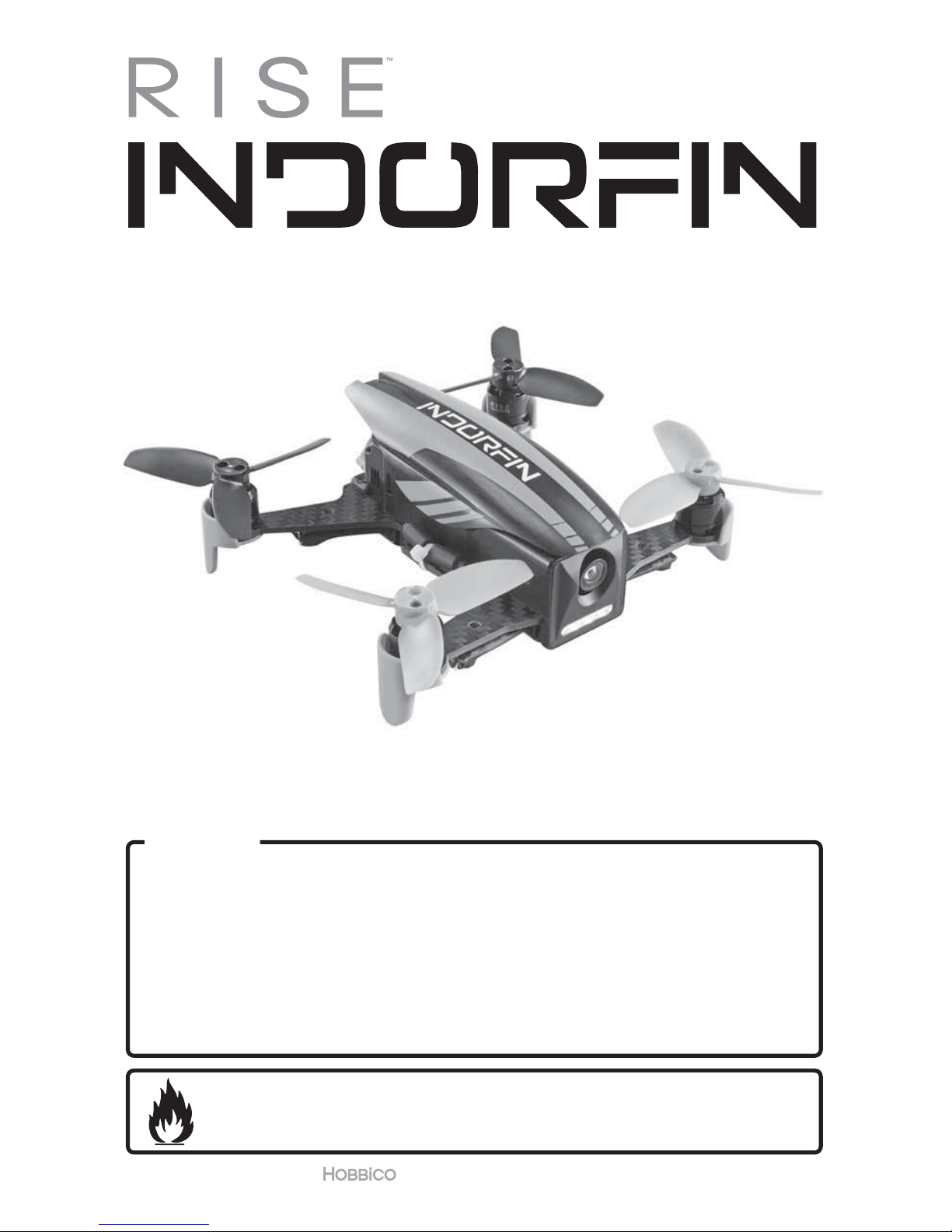
INTRODUCTION
Thank you for purchasing the INDORFIN 130 RACER. We want the time you spend
with your new R/C quadcopter to be fun and successful, so please read the entire
manual before beginning setup. If for any reason you think this R/C model is not
for you, return it to the dealer immediately. Your dealer cannot accept returns on
any model after final assembly.
For the latest technical updates or manual corrections for the INDORFIN 130
RACER please visit the RISE web site at www.explore-rise.com. If there is any new
technical information, changes or important updates to this model, a “tech notice”
box will appear on the page. Click the “tech notice” box to learn more.
LITHIUM BATTERY WARNING!
This product includes a lithium polymer (LiPo) battery. Improper
handling could result in FIRE! A lithium battery fire has the potential
to ignite surrounding areas and may cause property damage or cause
personal injury.
For safe LiPo handling, follow all of these guidelines. If you are unable to follow
these guidelines, return this product to the place of purchase.
●MOST IMPORTANT! NEVER leave the charger and LiPo battery unattended
while charging.
●Keep out of reach of children!
●NEVER charge a LiPo battery on a flammable surface or near combustible
materials.
●NEVER charge inside a vehicle or at a location that could be damaged in the
event of a LiPo fire.
●Do not charge or use a battery that is deformed, bent, crushed or has any type
of visible damage.
●Only use the included factory approved charger with this LiPo battery.
●ALWAYS keep a supply of sand accessible when charging. Dumping sand on
the battery will assist in extinguishing a LiPo chemical fire.
●It is normal for the charger to become warm to the touch. However, disconnect
the battery and unplug the charger immediately if either becomes hot, begins
to swell, or smoke!
●Disconnect the battery and unplug the charger if the charge time exceeds 2 hours.
●ALWAYS disconnect the battery and unplug the charger after the charge
is complete.
●ALWAYS disconnect and remove the battery from your model immediately
following operation.
●ALWAYS store/transport LiPo batteries in a fireproof container away from
combustible materials.
●NEVER put a LiPo battery in the pocket of any clothing.
●Keep LiPo batteries out of reach of animals. A punctured battery may cause a fire.

3
●Do not use the included charger for any battery other than the one included
with this model.
●In the event of a crash, place the battery into a fireproof container immediately.
Examine the battery for damage before further use.
●Only operate and store batteries between 40-110° F (4-43° C).
●NEVER allow the battery temperature to exceed 140° F [60° C] during operation.
●NEVER disassemble or modify a battery, its wiring, or puncture cells, as this
may result in fire.
●Do not allow the battery to short circuit by touching exposed wires together.
●Stop the operation of your model immediately when the battery power
is low. A battery failure can occur when attempting to recharge an over-
discharged battery.
●LiPo batteries must always be recycled or disposed of properly.
WARRANTY
RISE™ guarantees this kit to be free from defects in both material and workmanship
at the date of purchase. This warranty does not cover any component parts
damaged by use or modification. In no case shall RISE’s liability exceed the original
cost of the purchased kit. Further, RISE reserves the right to change or modify this
warranty without notice. In that RISE has no control over the final assembly or
material used for final assembly, no liability shall be assumed nor accepted for any
damage resulting from the use by the user of the final user assembled product. By
the act of using the user assembled product, the user accepts all resulting liability.
If the buyer is not prepared to accept the liability associated with the use of this
product, the buyer is advised to return this kit immediately in new and unused
condition to the place of purchase.
To make a warranty claim, please contact our support team at
www.explore-rise.com/support
SAFETY PRECAUTIONS
Failure to follow these safety precautions
may result in injury to yourself and others.
●Keep your face and body as well as all spectators away from the rotating plane
of the blades whenever the battery is connected. Keep loose clothing, shirt
sleeves, ties, scarfs, long hair or loose objects such as pencils or screwdrivers
that may fall out of shirt or jacket pockets away from the rotors. The spinning
blades of a model quadcopter can cause serious injury. When choosing a
flying site for your INDORFIN 130 RACER, stay clear of buildings, trees and
power lines. AVOID flying in or near crowded areas. DO NOT fly close to
people or pets. Maintain a safe distance from the quadcopter.
●Your INDORFIN 130 RACER should not be considered a toy. Because of its
performance capabilities, the INDORFIN 130 RACER, if not operated correctly,
could cause injury to you or spectators and damage to property.

4
●DO NOT alter or modify the model. Doing so may result in an unsafe or
unflyable model.
●When and if repairs are necessary you must correctly install all components so
that the model operates properly on the ground and in the air. Please check
the operation of the model before every ight to insure that all equipment is
operating and that the model has remained structurally sound. Be sure to check
connectors and the propellers before each ight. Replace them if they show
any signs of wear or fatigue.
KNOW BEFORE YOU FLY
As a new owner of an unmanned aircraft system (UAS), you are responsible for
the operation of this vehicle and the safety of those around you. Please contact
your local authorities to find out the latest rules and regulations.
knowbeforeyouy.org faa.gov/uas
AMA
We urge you to join the AMA (Academy of Model Aeronautics)
and a local R/C club. The AMA is the governing body of
model aviation and membership is required to fly at AMA
clubs. Though joining the AMA provides many benefits, one
of the primary reasons to join is liability protection. Coverage is not limited to
flying at contests or on the club field. It even applies to flying at public demonstrations
and air shows. Failure to comply with the Safety Code may endanger insurance
coverage. Additionally, training programs and instructors are available at AMA
club sites to help you get started the right way. There are over 2,500 AMA
chartered clubs across the country. Contact the AMA via the Internet at: www.
modelaircraft.org
IMPORTANT: Two of the most important things you can do to preserve the radio
controlled aircraft hobby are to avoid flying near full-scale aircraft and avoid
flying near or over groups of people.
FEATURES
●
130 class racing quad
●
Modular Oneshot125 speed controls, no
soldering required
●
4100Kv 1104 size Brushless motors
●
Ready to fly, no building required
●
Flight Controller is pre-programmed, no
setup needed
●
600TVL FPV Camera
●
200mW 40 channel VTX (25mW is
available)

5
DIMENSIONS
Size: 135mm (5.3 in.) diagonal motor to motor
Width: 127mm (5.0 in.)
Length: 108mm (4.3 in.)
Height: 47mm (1.9 in.)
Prop: 70mm (2.75 in.) 3 blade propeller diameter
Weight: 106g (3.7 oz.) without battery
Indorn RTF Racer Contents
●RISE Indorfin Racer
●Transmitter
●FPV Goggle and Monitor with
antenna
●Goggle Foam
●740mA 3s LiPo
●2S/3S LiPo Charger with AC
adapter
●Spare Props
●Prop Guards
●AA batteries
●Screwdriver
Indorn FPV-R Racer Contents
●RISE Indorfin Racer
●740mA 3s LiPo
●Spare Props
●AA batteries
●Screwdriver
●Receiver Cable
SETUP
UNBOXING
Remove the contents of the box and become
familiar with the included parts. To easily
remove the transmitter from the packaging,
push outward at the location shown while
lifting up on the transmitter from the same side.
LOW BATTERY ALARM
When the flight battery voltage gets low, the drone will beep to indicate that it
needs to land soon.
WARNING – Do not continue flying the Indorfin until the battery voltage is too
low for the drone to stay in the air. The battery can be damaged if the voltage
drops below 3.0 volts per cell (9 volts).
BETAFLIGHT CONFIGURATOR INSTALLATION
The Indorfin flight controller has Betaflight firmware loaded. To test the controls
and make changes to the settings, the Betaflight Configurator app must be loaded
on your PC. Download and install the Betaflight Configurator app from the Chrome
Web Store. Open the app and click on the link for the latest CP210x driver. Install
the driver and connect the Indorfin to your PC with a micro USB cable (not included).
After the drone is connected to your PC, select the COM port in in the Betaflight
Table of contents
Other Rise Quadcopter manuals


