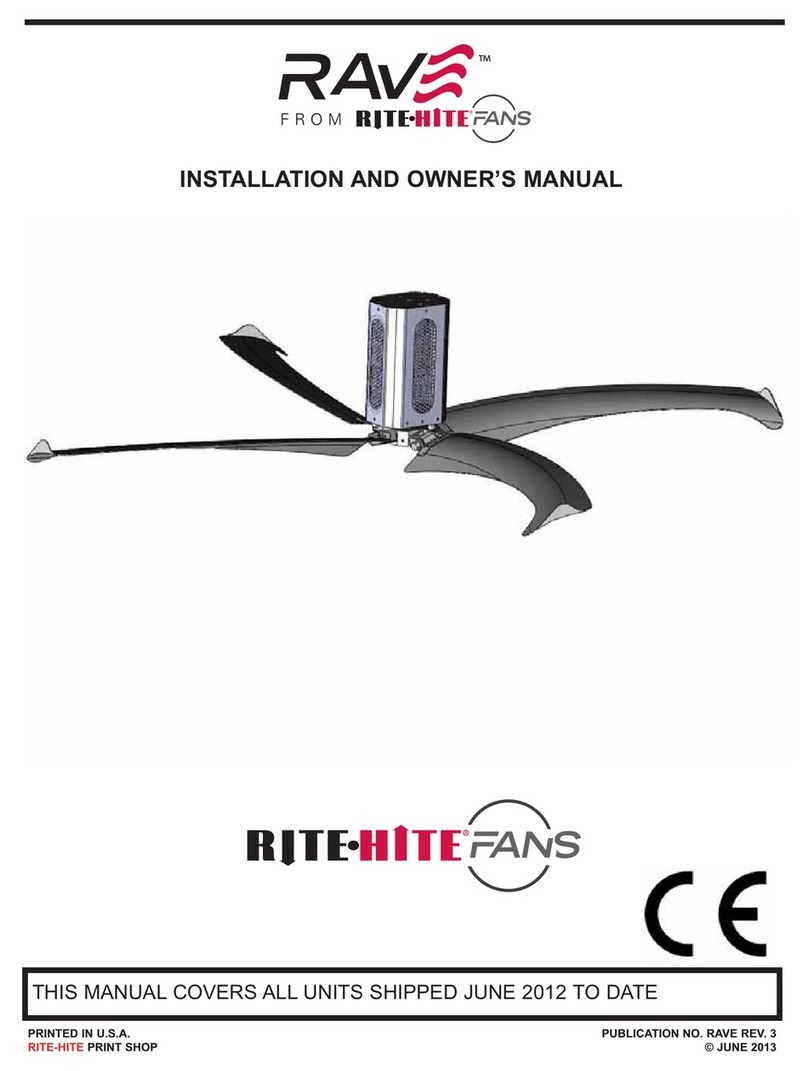
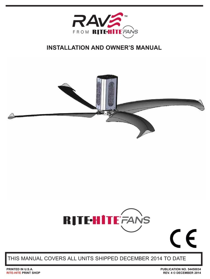
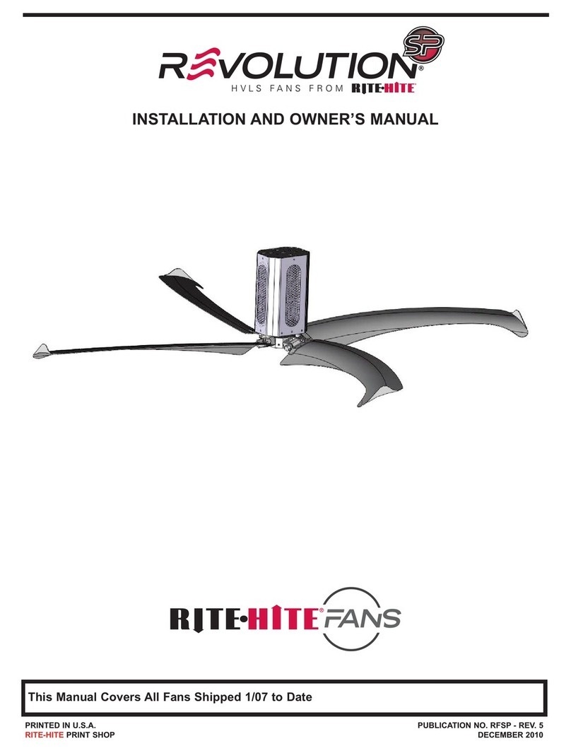
RITE-HITE Revolution Installation instructions

THIS MANUAL COVERS ALL UNITS SHIPPED 1/07 TO DATE
PRINTED IN U.S.A. PUBLICATION NO. RCF
RITE-HITE PRINT SHOP JANUARY 2007
AFTERMARKET
CORPORATION
REVOLUTIONTM
HV/LS FAN
INSTALLATION AND OWNER’S MANUAL

TABLE OF CONTENTS
REVOLUTIONTM FAN
2Pub. No. RF - JANUARY 2007
SAFETY WARNINGS . . . . . . . . . . . . . . . . . . . . . . . . . . . . . . . . . . . . . . . . . . . . . . . . . . . . . . . . .3
UNPACKING OF PARTS . . . . . . . . . . . . . . . . . . . . . . . . . . . . . . . . . . . . . . . . . . . . . . . . . . . . . .4
TOOLS REQUIRED . . . . . . . . . . . . . . . . . . . . . . . . . . . . . . . . . . . . . . . . . . . . . . . . . . . . . . . . . .4
MOUNTING OF FAN . . . . . . . . . . . . . . . . . . . . . . . . . . . . . . . . . . . . . . . . . . . . . . . . . . . . . . . . .5
I BEAM MOUNTING . . . . . . . . . . . . . . . . . . . . . . . . . . . . . . . . . . . . . . . . . . . . . . . . . . . . . . . . .6
SUPPORT CHANNEL MOUNTING . . . . . . . . . . . . . . . . . . . . . . . . . . . . . . . . . . . . . . . . . . . . . .6
ATTACHMENT OF MOTOR BRACKET . . . . . . . . . . . . . . . . . . . . . . . . . . . . . . . . . . . . . . . . . . .7
SAFETY CABLE . . . . . . . . . . . . . . . . . . . . . . . . . . . . . . . . . . . . . . . . . . . . . . . . . . . . . . . . . . . . .7
STABILIZATION CABLE . . . . . . . . . . . . . . . . . . . . . . . . . . . . . . . . . . . . . . . . . . . . . . . . . . . . . .8
BLADE ATTACHMENT . . . . . . . . . . . . . . . . . . . . . . . . . . . . . . . . . . . . . . . . . . . . . . . . . . . . . . . .8
GUARDING THE FAN . . . . . . . . . . . . . . . . . . . . . . . . . . . . . . . . . . . . . . . . . . . . . . . . . . . . . . . .8
FIELD WIRING DIAGRAM . . . . . . . . . . . . . . . . . . . . . . . . . . . . . . . . . . . . . . . . . . . . . . . . . . . . .9
CONTROL BOX WIRING . . . . . . . . . . . . . . . . . . . . . . . . . . . . . . . . . . . . . . . . . . . . . . . . . . . . .10
CONTROL BOX MOUNTING . . . . . . . . . . . . . . . . . . . . . . . . . . . . . . . . . . . . . . . . . . . . . . . . . .11
MOTOR WIRING . . . . . . . . . . . . . . . . . . . . . . . . . . . . . . . . . . . . . . . . . . . . . . . . . . . . . . . . . . .12
ANNUAL PLANNED MAINTENANCE . . . . . . . . . . . . . . . . . . . . . . . . . . . . . . . . . . . . . . . . . . .14
TROUBLE SHOOTING . . . . . . . . . . . . . . . . . . . . . . . . . . . . . . . . . . . . . . . . . . . . . . . . . . . . . .15
PARTS LIST – CEILING BRACKET . . . . . . . . . . . . . . . . . . . . . . . . . . . . . . . . . . . . . . . . . . . .18
PARTS LIST – LOWER BRACKET – MOTOR BRACKET . . . . . . . . . . . . . . . . . . . . . . . . . . .19
PARTS LIST – FAN BLADES . . . . . . . . . . . . . . . . . . . . . . . . . . . . . . . . . . . . . . . . . . . . . . . . . .20
PARTS LIST –
STABILIZATION CABLES-CONTROL BOXES-LABEL PLATE-EXTENSION TUBE . . . . . . . . .21
WARRANTY . . . . . . . . . . . . . . . . . . . . . . . . . . . . . . . . . . . . . . . . . . . . . . . . . . . . . . . . . . . . . . .24
PRODUCT INTRODUCTION
Thank you for purchasing the RevolutionTM Fan from RITE-HITE AFTERMARKET CORPORATION.
IMPORTANT
Read and understand contents of this manual prior to installation or operation of this equipment.
For best results, have this product serviced by your authorized RITE-HITE®Aftermarket
representative.
NOTICE TO USER
Your local RITE-HITE AFTERMARKET CORPORATION Representative provides the Planned
Maintenance Program (P.M.P.) which can be fitted to your specific operation. Call your local
representative or RITE-HITE AFTERMARKET CORPORATION at 1-414-355-2600 or toll free at
1-800-456-0600.

REVOLUTIONTM FAN
Pub. No. RF - JANUARY 2007 3
SAFETY WARNINGS
This is the highest level statement. Failure to
follow the listed instructions will most likely
result in severe injury or death.
IMPORTANT is used to draw attention
to a procedure that needs to be followed to
prevent machine or property damage.
When working with electrical or electronic
controls, make sure that the power source has
been locked out and tagged according to OSHA
regulations and approved local electrical codes.
This is a statement of serious hazard. Failure to
follow the listed instructions could place the
individual at risk of serious injury or death.
The statements used with this level of
warning deal with a safe operating
procedure. If the procedure is ignored, the
possibility of personal injury may exist.
WARNING!!!
!
WARNING!!!
!
CAUTION !!!
!
DANGER !!!
!
IMPORTANT!!!
LOCKOUT/TAGOUT PROCEDURES
The Occupational Safety and Health Administration requires that, in addition to posting safety warnings and
barricading the work area, the power supply has been locked in the OFF position or disconnected. It is mandatory
that an approved lockout device is utilized. An example of a lockout device is illustrated above. The proper lockout
procedure requires that the person responsible for the repairs is the only person who has the ability to remove the
lockout device.
In addition to the lockout device, it is also a requirement to tag the power control in a manner that will clearly note
that repairs are under way and state who is responsible for the lockout condition. Tagout devices have to be
constructed and printed so that exposure to weather conditions or wet and damp locations will not cause the tag to
deteriorate or become unreadable.
RITE-HITE®Corporation does not recommend any particular lockout device, but recommends the utilization of a
device that meets OSHA standards (refer to OSHA regulation 1910.147). RITE-HITE®Corporation also recommends
the review and implementation of an entire safety program for the Control of Hazardous Energy (Lockout/Tagout).
These regulations are available through OSHA publication 3120.

REVOLUTIONTM FAN
4Pub. No. RF - JANUARY 2007
UNPACKING OF THE COMPONENTS
You should have received the following items:
(2) boxes of fan blades, they are packed (2) per box for a total of (4) blades – approximately 50
lb. per box.
(1) motor / hub assembly – approximately 160 lb.
(1) box containing miscellaneous mounting hardware and cables - approximately 50 lb.
(1) box containing the control box – approximately 35 lb.
Insure you have received all of the above items before installation begins. Notify the factory if
parts are missing or damaged.
TOOLS REQUIRED:
(2) 7/16” wrenches
(2) 1/2” wrenches
(2) 9/16” wrenches
(2) ¾” wrenches
(1) Vice grip
(1) Large standard screwdriver
(1) Small standard screwdriver
(1) Torque wrench capable of 200 ft-lb
(1) ¾” square drive for torque wrench
(1) Metric 7mm deep well socket
(1) 1/4” cable cutter
If you are mounting to support angles that span building joists, you will also need a
drill and a ½” drill bit

REVOLUTIONTM FAN
Pub. No. RF - JANUARY 2007 5
MOUNTING OF THE FAN
FAN WEIGHT AND TORQUE
The weight of the fan that will be suspended
from the ceiling is approximately 300 lbs. and
will generate torque of up to 300 ft-lb.
IMPORTANT!!!
FAN DISTANCE FROM CEILING AND
OBSTRUCTIONS
The blades on the Rite-Hite Revolution Fan
are angled upward to provide improved
airflow. A combination of centrifugal force
and air pressure cause the blades to move
upward to their operating position. Measure
the distance to possible obstructions and
mount the fan accordingly using the diagram
below to insure the blades will have proper
clearance in all areas when the fan is
running. Whenever possible allow 12”
additional clearance to existing obstructions.
IMPORTANT!!!

REVOLUTIONTM FAN
6Pub. No. RF - JANUARY 2007
I-BEAM MOUNTING
If the fan is being mounted to a building
support I-beam (6-14 inches wide) the fan can
be mounted directly to the beam with the
brackets provided. Clamp the brackets around
the beam as shown using the holes in the
upper beam mounting bracket that are closest
to the edge of the beam. See figure below. For
beams that are larger than the bracket,
(greater than 14 inches wide) clamp the
bracket on one edge of the beam and drill
holes through the beam to bolt the other side
securely. Use only grade 8 hardware.
Use a level to insure the extension tube is
hanging vertical.
SUPPORT CHANNEL MOUNTING
Never mount the fan to only one building
joist. One joist will not provide the rigidity and
support necessary for the fan during operation.
When using a support channel to span (2)
building joists you must use material that will
securely support the fan. We recommend
using (2) pieces of 3” x 3” x .25” angle. These
angles should be mounted in a way such that
the fan can be hung using the standard I-beam
mounting bracket. See the figure below. The
angles should be securely mounted to the
building joists to insure the angles cannot
move. Use a level to insure the extension tube
is hanging vertical.

REVOLUTIONTM FAN
Pub. No. RF - JANUARY 2007 7
ATTACHMENT OF MOTOR BRACKET
The motor bracket attaches to the extension
rod with (2) ½” x 4.5” long – grade 8 bolts,
washers and lock nuts. Position the motor
bracket so that one angle is on each side of the
extension tube. The bolts can be inserted
through the holes in the angles at the top of the
motor bracket and through the extension rod
and back through the second angle. Tighten
both lock nuts securely. When an extended
down rod is used, the smaller square tubing (3”
x 3”) will telescope
inside the larger
square tubing (3.5” x
3.5”) The brackets
on the top of the
motor bracket are
bolted in slots to
allow the larger tube
to bolt to the top of
the motor. The 3” x
3” tube should
always bolt to the
ceiling bracket.
SAFETY CABLES
Cables are included with this kit to wrap
around the bolted brackets at the ceiling and
the top of the extension tube. A second
cable should be wrapped through the bottom
of the extension tube and the top of the
motor housing. On adjustable length
extension tubes, a third cable should be
used to secure the center bolted joint of the
extension tubes. These cables support the
fan to the ceiling if one of the bolted joints
were to come loose. Secure the cables with
the cable clamps that are provided. See
figures to the right.
IMPORTANT!!!

REVOLUTIONTM FAN
8Pub. No. RF - JANUARY 2007
STABILIZATION CABLES
Cables are included with the kit to attach the
fan bracket back to the ceiling in (4)
locations. These cables will help to stabilize
the fan for any situations such as cross
winds or impacts which may otherwise be
strong enough to tilt the fan and cause the
blades to impact a ceiling joist or other
object. These cables are secured at the
ceiling with (2) cable clamps and tightened
with a turnbuckle. Cut cable to length as
required.
IMPORTANT!!!
BLADE ATTACHMENT
The fan blades are set in place on the fan
hub. Raise the blade above the arm of the
hub and allow the blade to slide into the slot
provided on the hub. Each fan blade is then
attached to the hub with a 1” bolt that is
provided. Use a torque wrench with a ¾”
drive extension to tighten the bolt to 200 ft-lb.
When properly tightened the blade will tilt
upward from the hub at approximately 6
degrees. Clean each blade with a paper
towel to remove fingerprints and dirt before
the blades are installed.
IMPORTANT!!! GUARDING THE FAN
A fan should be guarded if there is potential
for a person or object to come into contact
with moving blades. In some cases this
guarding can be a structure which is built
near the edge of the blades to keep fork
trucks and other objects from entering a
danger area. In other cases such as when
fans are mounted on low ceilings, it may be
necessary to build a “cage” around the fan
blades to insure objects do not come into
contact with the moving blades. It will be
best to mount this cage independent of the
fan and support it from the ceiling or columns
as necessary.
IMPORTANT!!!

REVOLUTIONTM FAN
Pub. No. RF - JANUARY 2007 9
FIELD WIRING DIAGRAM

REVOLUTIONTM FAN
10 Pub. No. RF - JANUARY 2007
CONTROL BOX WIRING

REVOLUTIONTM FAN
Pub. No. RF - JANUARY 2007 11
CONTROL BOX MOUNTING
Mount the control box securely to a wall or building column with appropriate anchors (not
provided). The box should not be greater than 200 ft. from the fan it is controlling. The fan should
be visible from where the control box is mounted.
RECOMMEND FUSE RATINGS
Recommended Branch Recommended
Circuit Protection Incoming Service
Input Voltage Amps Amps
200-240V, 1PH, 60 Hz. 20A 30A
200-240V, 3PH, 60 Hz. 15A 20A
460-480V, 3 PH, 60 Hz. 10A 15A
380V, 3PH, 50 Hz. 10A 15A
575V, 3PH, 60 Hz. 6A 10A
INPUT WIRING
Bring the input wires into the bottom of the fuse block. Tighten the screws to secure the wires.
Insert the wires that are going to the motor into the contact blocks that are labeled U, V, W.
Insert the ground wire into the green contact block.
MOTOR RATING
Motor
Input Voltage Volts Freq. F.L.A
200-240V, 1PH, 60 Hz. 230 60 6.3
200-240V, 3PH, 60 Hz. 400 50 3.5
460-480V, 3 PH, 60 Hz. 460 60 3.15
380V, 3PH, 50 Hz. 575 60 3.15
575V, 3PH, 60 Hz. 575 60 2.5
Increasing the speed of the fan beyond
factory set limits is not recommended and
can shorten the life of the motor.
WARNING!!!
!

REVOLUTIONTM FAN
12 Pub. No. RF - JANUARY 2007
MOTOR WIRING
The fan motor will receive three phase power
from the fan control box even if single phase
power is provided to the control box. Remove
the cover from the motor junction box. Change
the wire leads as necessary for high or low
voltage. See the diagram below for the
appropriate wiring.
Do not use solid core wiring of any size
or insulation class for controller output /
motor leads.
IMPORTANT!!!
Use one of the wire types listed below to
connect the fan control box to the motor.
Acceptable unshielded cable types:
THHN / THNW, rated for 600V and
75 deg. to 90 deg. Celsius
Acceptable shielded cable types:
RHH / RHW-2, rated for 600V and 75
deg to 90 deg. Celsius
Belden 29501 through 29507
RHH / RHW-2, tray rated for 600V
and 75 deg. to 90 deg. Celsius
Shawflex 2ACD / 3ACD or
equivalent.
IMPORTANT!!!

REVOLUTIONTM FAN
Pub. No. RF - JANUARY 2007 13
MOTOR WIRING
CONDUIT RESTRICTIONS
AC supply lines for a controller MAY
share the same conduit with AC supply
lines for one or more additional
controllers.
AC supply lines for a controller and
output / motor leads for the same
controller or another controller MAY NOT
share the same conduit.
LABEL PLATE ATTACHMENT
Use (4) .25 -20 x 1.0” bolts with lock washers
to attach the label plate mounting brackets to
the bottom of the fan hub. Insert the bolts
through the end with the round hole. Align the
bracket so the slotted hole faces outward
toward the fan blade. Repeat this process for
the remaining (3) brackets. Do not tighten
completely until the label plate is attached.
Attach the label plate to the label plate brackets
by inserting the bolt up through the label plate
and through the label plate bracket. Install a
.25-20 nylok nut on the bolt to secure it in
position. You may need to puncture a small
hole through the label with a sharp object to
insert the bolt. Repeat this process to attach
the label plate to the remaining label plate
brackets. Tighten all of the bolts holding the
brackets and the label plate securely.
MOTOR COVER ATTACHMENT
The motor cover is attached over the motor
bracket with (4) .25-20 x 1.0” bolts with
locknuts. Insert the bolt through the cover and
motor bracket. Secure with a nylok nut on the
inside. Repeat this for the other (3) bolts and
tighten securely.
LAMINATED BEAM BRACKETS
(OPTIONAL)
The laminated beam brackets are through
bolted with one bracket on each side of the
laminated (or concrete) beam. The standard
ceiling mounting bracket should then be
attached to this bracket in the normal manner.
RUN / TEST
Turn the power disconnect switch on the
control box to the ON position. Allow a few
seconds for the frequency drive to power up.
Turn the Fan Control to the ON position.
Watch the rotation of the fan. The fan should
turn clockwise when you are standing below
the fan looking up. If the rotation is the wrong
direction, disconnect power to the control box
and reverse two of the three wires from the
control box to the motor.
LOSS OF POWER
Both the disconnect and the ON/OFF
switches must be turned to the OFF
positions to restart the fan. Turn the
disconnect switch to the ON position.
Wait 5 seconds for the variable frequency
drive to power up before turning the fan
switch to the ON position.
IMPORTANT!!!

REVOLUTIONTM FAN
14 Pub. No. RF - JANUARY 2007
ANNUAL PLANNED MAINTENANCE
FAN BLADE CLEANING
• Dirt and dust may be removed from the
blades by using a cloth or soft non-metallic
brush.
• Stubborn stains may be removed with a
cloth dampened with a mild detergent
solution. Do not use strong solvents.
FAN MOUNTING:
• Re-torque all fasteners [1/2-13 Grade 8 (98
ft-lbs)], [5/16-18 Grade 8 (29 ft-lbs)].
• Check the fan, including mounting supports
to make sure all hardware is tight and
shows no wear and tear.
CABLES:
• Retorque clamps.
• Check for fraying or wear.
GEAR REDUCER:
• Check for oil leaks.
MOTOR:
• Check motor for accumulated dust and dirt.
Remove using a brush or compressed air.
FAN CONTROLLER:
• Examine all terminal connections inside the
control box, tighten any loose connections.
• Use compressed air at 90~100 psi, to blow
loose debris and dust out of controller
interior.
When cleaning or attempting to re-torque you
must unplug or disconnect the fan and
controller from the power supply.
WARNING!!!
!

REVOLUTIONTM FAN
Pub. No. RF - JANUARY 2007 15
TROUBLE SHOOTING
MOTOR WOBBLE
Insure all hardware is tight. Insure stabilization cables are taunt.
Insure the motor bracket is installed vertical. Tighten all mounting hardware and secure in the
vertical position by tightening the appropriate stabilization cable.
HIGH FREQUENCY MOTOR NOISE
If you are installing a fan in an area where it is abnormally quiet, you may notice a high
frequency noise from the motor. You can adjust setting A091 (PWM Frequency) to a higher
level to minimize this noise. The standard setting is 4KHz. This can be adjusted up to 12kHz.
Increasing this setting will cause the motor to run warmer. Adjust this only as high as
necessary to eliminate the objectionable noise.
FREQUENCY DRIVE FAULTS
#NAME ACTION
F002 AUXILIARY INPUT Check remote wiring
F003 POWER LOSS Monitor incoming power lines for low power or power interruption.
F004 UNDER VOLTAGE Monitor incoming power lines for low power or power interruption.
F005 OVER VOLTAGE Monitor incoming power lines for high line voltage or transient
conditions. Install Line reactor if voltage spikes are common. Install step
down transformer if voltage is high. Activate A092 / A093 if spikes are
random and it is acceptable for the fan to restart itself.
F006 MOTOR STALLED Current trip was activated by something that physically stopped the fan
movement. Check fan for damage. Restart if no damage is detected.
Contact Rite-Hite if damage is found.
F007 MOTOR OVERLOAD
This signals the motor is drawing too much current. Under normal
operation this will not occur.
Check to insure motor wiring matches voltage provided.
Check for any mechanical interference causing extra load.
Check wire length from control box to motor. Is it greater than 200ft?
Check to insure input wiring is not in same conduit as wiring to motor.
Check to insure output wiring for multiple fans is not run in same
conduit.
F008 HEATSINK OVERTEMP
Temperature inside of control box is greater than 122F.
Check to insure the fan on the frequency drive is operational.

REVOLUTIONTM FAN
16 Pub. No. RF - JANUARY 2007
TROUBLE SHOOTING CONTINUED
FREQUENCY DRIVE FAULTS CONTINUED
#NAME ACTION
F12 OVER CURRENT
Check for excessive load.
Check to insure motor wiring matches voltage provided.
Check for any mechanical interference causing extra load.
Check wire length from control box to motor. Is it greater than
200ft?
Check to insure input wiring is not in same conduit as wiring to
motor.
Check to insure output wiring for multiple fans is not run in
same conduit.
F13 GROUND FAULT
Check the motor and external wiring to the drive output
terminals for a grounded condition.
F33 AUTO RESTART TRIES
Correct the cause for Auto restart and manually clear.
F38 PHASE U TO GROUND
Check the wiring between the drive and the motor. Check
motor for grounded phase. Replace drive if fault cannot be
cleared.
F39 PHASE V TO GROUND
Check the wiring between the drive and the motor. Check
motor for grounded phase. Replace drive if fault cannot be
cleared.
F40 PHASE W TO GROUND
Check the wiring between the drive and the motor. Check
motor for grounded phase. Replace drive if fault cannot be
cleared.
F41 PHASE UV SHORT
Check the motor and drive output wiring for shorted condition.
Replace drive if fault cannot be cleared.
F42 PHASE UW SHORT
Check the motor and drive output wiring for shorted condition.
Replace drive if fault cannot be cleared.

REVOLUTIONTM FAN
Pub. No. RF - JANUARY 2007 17
TROUBLE SHOOTING CONTINUED
FREQUENCY DRIVE FAULTS CONTINUED
#NAME ACTION
F43 PHASE VW SHORT Check the motor and drive output wiring for shorted condition.
Replace drive if fault cannot be cleared.
F122 I/O BOARD FAIL Cycle power. Replace drive if fault cannot be cleared.
F63 SW OVER CURRENT Check load requirements and A098 setting. Current trip was
activated by something that physically stopped the fan
movement. Check fan for damage. Restart if no damage is
detected. Contact Rite-Hite if damage is found.
F64 DRIVE OVERLOAD Reduce load
F70 POWER UNIT Cycle power. Replace drive if fault cannot be cleared.

REVOLUTIONTM FAN
18 Pub. No. RF - JANUARY 2007
PARTS
CEILING MOUNT BRACKET
ITEM PART# QTY DESCRIPTION
125353 1 Ceiling Mount Bracket Assembly (includes the following parts)
1 125354 1 Ceiling Mount Bracket
2 125355 2 Spacer
3 125356 2 Clamp Plate
4 125338 4 Bolt, .5"-13 x 2", Grade 8
5 125339 6 Nut, .5"-13, Nylock, Grade 8
6 125340 2 Bolt, .5"-13 x 4.5", Grade 8
7 51709 12 Washer, .5", Flat
5
3
2
1
4
67

REVOLUTIONTM FAN
Pub. No. RF - JANUARY 2007 19
PARTS
LOWER BRACKET HARDWARE
ITEM PART# QTY DESCRIPTION
125335 1 Motor Bracket Assembly (Includes the following parts)
1 125336 1 Motor Bracket
2 125337 2 Top Angle
3 125338 4 Bolt, .5"-13 x 2", Grade 8
4 125339 6 Nut, .5"-13, Nylock, Grade 8
5 125340 2 Bolt, .5"-13 x 4.5", Grade 8
6 51709 8 Washer, .5", Flat
7 125341 1 Motor Cover, 16 G, Fan (not shown)
8 125342 1 Safety Ring
9 125343 8 Bolt, ..3125"-18 x 1.0", Grade 8
10 125344 4 Bolt, .3125-18 x 1.5" Grade 8
11 125345 12 Nut, .3125"-18, Nylock, Grade 8
12 125346 4 Bracket, Safety Ring
13 125347 4 Bolt, .5"-13 X 1", Grade 8
14 51831 4 Washer, Lock, .5"
15 125348 4 Bolt, .25-20 x 1.0", Grade 5 (not shown)
16 125349 4 Nut .25-20, Nylock, Grade 5 (not shown)
17 125350 14 Bolt .375-16 x 1.25 Grade 8
18 125351 18 Nut .375-16 Nylk Grade 8
19 125352 4 Eyelet .375" x 2" (not shown)
MOTORS
PART# QTY DESCRIPTION
125046 1 2 HP, 240/480 V, 3 PH, 60 Hz., 48 RPM
125047 1 2 HP, 240/480 V, 3 PH, 60 Hz., 58 RPM
125048 1 2 HP, 240/480 V, 3 PH, 60 Hz., 70 RPM
125049 1 2 HP, 240/480 V, 3 PH, 60 Hz., 100 RPM
125050 1 2 HP, 575 V, 3 PH, 60 Hz., 48 RPM
125051 1 2 HP, 575 V, 3 PH, 60 Hz., 58 RPM
125052 1 2 HP, 575 V, 3 PH, 60 Hz., 70 RPM
125053 1 2 HP, 575 V, 3 PH, 60 Hz.,100 RPM
125054 1 2 HP, 380 V, 3 PH, 50 Hz.,48 RPM
125055 1 2 HP, 380 V, 3 PH, 50 Hz.,58 RPM
125056 1 2 HP, 380 V, 3 PH, 50 Hz., 70 RPM
125057 1 2 HP, 380 V, 3 PH, 50 Hz., 100 RPM
17,18
5
4
2
3,6
1
19
9,11
8
10
12,13,14

REVOLUTIONTM FAN
20 Pub. No. RF - JANUARY 2007
PARTS
FAN BLADES
PART# QTY DESCRIPTION
125042 1 Hub and (4) blade assembly, 12' (Includes the parts below)
125037 1 Hub, 2', 28 deg. Blade angle
125038 2 (2) Blade set, 12'
125043 1 Hub and (4) blade assembly, 16' (Includes the parts below)
125036 1 Hub, 2', 26 deg. Blade angle
125039 2 (2) Blade set, 16'
125044 1 Hub and (4) blade assembly, 20' (Includes the parts below)
125036 1 Hub, 2', 26 deg. Blade angle
125040 2 (2) Blade set, 20'
125045 1 Hub and (4) blade assembly, 24' (Includes the parts below)
125036 1 Hub, 2', 26 deg. Blade angle
125041 2 (2) Blade set, 24'
Table of contents
Other RITE-HITE Fan manuals
Popular Fan manuals by other brands

Broan
Broan HRV150S Series user manual

Princess
Princess 352500 Instructions for use

enervent
enervent greenair Plaza eco EC Planning, installation and operational instructions manual

NuAire
NuAire AX installation manual

Vortice
Vortice Nordik Design 1S Instruction booklet

wolter
wolter RH operating instructions

Gorenje
Gorenje BVN WS Series Instructions for installation and use

STIEBEL ELTRON
STIEBEL ELTRON VCR 180 MC Operation and installation

Bimar
Bimar VT7-30B Instruction booklet

Incubator Warehouse
Incubator Warehouse Little Giant 9300 installation instructions

Perel
Perel CFANF45N user manual

Miele
Miele DUU 2900 Operating and installation instructions