RITS-N IRM203-UNI User manual

The Radar sensor unit
may be negatively affected
by metal close to or
in the detection area.
( )
Red
Black
White
Green
Yellow
Blue
Gray
Brown
Power (AC/DC 12V~24V)
Safety output
Test Input + (DC 12~24V)
Test Input -
Activation Output
sno
is
nemiD roiretxE .2noitpircseD .1
3. LED Indicators
6. Mounting & Wiring Information
Unit : mm
Max 50mmMax 50mm
DO NOT use any
flat head screws.
WARNING
Accessories
Mounting
template
User Manual
Cable 2.5m
Mounting screws
Cable Length(Min) 80mm
265
60
42.5
Drill screw (mounting) (Ø3.5mm) ③ Use a flathead screwdriver to remove cover.
and power cable (wiring) (Ø10mm)
holes.
① Attach the mounting template so that it is
placed within a 50mm distance from the
bottom edge of the door engine cover.
④ Controller wiring ⑤ Attach the sensor to the door
⑦ Attach the cover.
⑥ Connect the power connector.
1. Insert a flathead screwdriver as shown
2. Turn the screwdriver counterclockwise gently to prise the cover from the sensor body
⑧ How to remove the cover after installation
②
Green
LED Indicators
Blue
Red
Standby
Radar detection
IR or IR+Radar detection
w
o
l
o
ot
si y
tiv
i
t
c
elf
er d
e
rar
fnI
d
e
R
+
n
ee
r
G
IRM203-UNI
User Manual
IRM203-UNI
Mounting height of
3m (9.8 ft) or
lower.
Make sure that the
sensor is not directly
exposed to heavy
rainfall.
If possible, ensure there is
no accumulation of snow
or water on the floor.
Ensure the minimum
of reflected sunlight
from the floor.
Use different frequency
settings for sensors
in close proximity.
Mount within 50mm of
the bottom of the door
engine cover.
Ensure that there are
no moving objects in
the detection area.
Ensure that no
condensation gets
onto the sensor.
Infrared detection area setting to maximise pedestrian safety.
Side view Plan view
Moving door leaf Moving door leaf
Cover
Connector
Indicator LED
(Green/Red/Blue)
Settings display IR detection area
adjustment
IR sensor
unit
IR angle adjustment screw
Menu button
Change settings button
Set (Apply) button
Menu display
Radar sensor unit
IR sensitivity
volume
IR angle scale
Radar sensitivity
volume
AB
A
B
3m
(9.8ft )
Max 50mm
12
4. Mounting Precautions
AC12V: 300[mA] (Max) / AC24V: 200[mA] (Max)
(
~
),
DC12V: 160[mA] (Max) / DC24V: 80[mA] (Max)
±10 [%] @ 50/60[Hz]
6[mA] @ 24[VDC]
Test input
250[g]
Black
Weight
Power consumption
Color
-20 ~ 50[°C]
0.5 seconds
AC DC 12~24V
Infrared & Radar sensor detection
Radar detection area adjustment
(Installed height: 2.2 m)
S3 : 3 Step(15°)
S6 : 6 Step(30°)
S9 : 9 Step(45°)
S3 : 3 Step(15°)
S6 : 6 Step(30°)
S9 : 9 Step(45°)
detection module
vertical angle
detection module
vertical angle
Removing/assembling the Radar Sensor Detection Module
1. Twist with your index finger
in the indicated direction.
2. Hold and pull forward the upper part of the
module with your index finger.
3. After removing the module, turn 90 degrees
clockwise, and re-assemble.
90°
8. Detection
※Ensure that detection setting does not exceed the door.
Screw
Near Far
(Default Sensitivity)
Narrow
Wide
Wide
m
m
m
m
1.0 0
.
2
]
m[
0
.
21.0
1.0
2.0
2.2
3.0
0
Narrow
IR detection area width adjustment
IR detection area depth adjustment
2 sec
i
Bi
n
U
30 sec 60 sec
CN
ON
CN
ON
without TEST With TEST without TEST without TEST With TEST without TEST
+++
+
Infrared presence
timer setting
Frequency
Setting
Safety Relay
Output
Radar unit
direction
detection
Activation
Relay Output
Factory
reset
Activation
Relay
Output
Configuration
TEST Input
Low reflection
setting
1.0[m] -0.5 0
1.0
2.0
2.2
3.0
3
row 2
row 1
row
[ Far ]
+4 Angle setting
Door
[ Near ]
1.0[m] -0.5 0
row row
1.0[m] -0.5 0
1.0
2.0
2.2
3.0
-8 Angle setting
Door

11. Troubleshooting
9. Operation check
<Disclaimer> The manufacturer shall not be held responsible for below
1. Misinterpretation of the installation instructions, poor connection, random disassembly and inappropriate installation.
2. Damage caused by inappropriate transportation.
3. Accidents or damages caused by fire, pollution, abnormal voltage, and natural disasters(Earthquake, lightning, wind, floods etc.)
4. Loss of business profits, business interruptions, business information losses and other financial losses
caused by malfunction or use of the sensor.
5. Total compensation beyond the selling price in all cases.
Problem LED Status Possible Causes Troubleshooting Measures
Door will not open even if a
person comes close to it. Off
Green
For no reason, the door
opens and closes
(ghosting)
A rain cover (sold separately) protects the sensor from snow and rain when installed outside.
Blue
Insert the sensor
connector correctly until it
clicks.
Supply the correct voltage
to the sensor.
(12~24V AC/DC)
Remove the moving object
from the detection area.
Reduce the radar sensitivity
volume to an appropriate value
according to the manual.
Activate the snow mode
setting
Set the presence timer
setting to 30 or 60 seconds.
Remove the highly reflective object
from the detection area or lower the
IR sensitivity volume.
Voltage failure
Defective wiring
There is a moving object
in the detection area
The radar sensitivity volume has
been set too high relative to the
installation environment.
Dust, frost, water droplets
are on the lens
Defective wiring
Excessive reflections in the infrared
detection area
Red
There is a moving object in the radar
detection area.
Remove the moving objects.
Radar
sensitivity volume
IR sensitivity
volume
12. Rain cover (not provided)
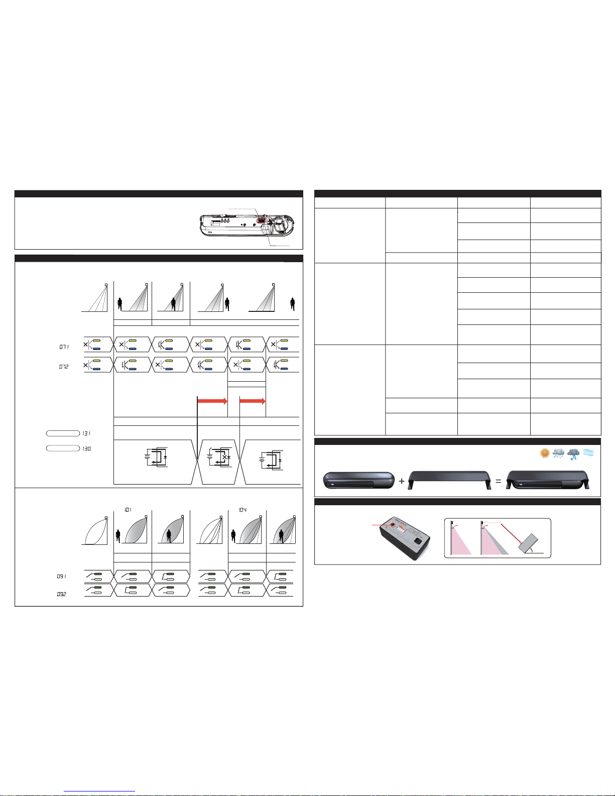
13. Spot finder (not provided)
A spot finder can be used to accurately locate the position of the infrared detection area and is a useful tool during the commissioning of this sensor.
MODEL : WC-IR/BL
Green + Red Infrared reflectivity is too low Adjust the mounting height or IR
sensitivity. If necessary, deactivate
low reflection setting(Menu:141)
An automatic doors
keeps open.
Set the frequency setting of both
sensors to be different (Menu: 041)
Detection area overlaps
with that of another sensor
Sensitivity value is too low Increase the radar sensitivity volume
to an appropriate value.
Loose connector
Recheck wiring
Green color after the red or blue Clean the sensor lens
Fallen leaves
Snowfall
Infinity presence timer setting used
Recheck wiring
45°
(o)(o) (x)
IR Sensor
0°~ 25° 0°~ 25°
SF100
Detection point of IR
yellow
blue
yellow
blue
yellow
blue
yellow
blue
yellow
blue
yellow
blue
yellow
blue
yellow
blue
yellow
blue
yellow
blue
yellow
blue
yellow
blue
Gray
Brown
Supplying DC 12 to 24V ,
make current flow from Gray to Brown.
It is under test state
when there is not
current flow.
sensor Gray
Brown
sensor
Gray
Brown
sensor
Green
White
Green
White
Green
White
Green
White
Green
White
Green
White
Green
White
Green
White
Green
White
Green
White
Green
White
Green
White
When it is used in automatic door controller in compatible with European standard EN16005,
the safety output signal timing can be checked based on the timing diagram below.
Safety Relay Output
/ Test Input Setting
Activation Relay Output
N.O.
N.C.
de
t
c
e
te
dn
Udet
c
et
eDde
tce
t
ed
nU
de
t
c
e
teD
d
etcetednUdetceteDd
e
tce
t
ednU
Power off
f
f
o
r
ewoP
f
fo
rew
oP
Menu
Menu
Menu
Menu
Menu
Menu
Menu Menu
N.O.
N.C.
Non-test Test Non-test
Test response DETECTION as
response to TEST
Test input used
Test input not used
DC12~24V
2 1
10. Timing of safety output signal
3 2 1
3 2 1 3 2 1 1 2
31
2 3
1
2
3
3 2 1 3 2 1
3 2 1 3 2 1 3 2 1
3 2 1
After completing installation, walk into the detection area of the sensor. If you feel that the detection
area is incorrect, then adjust it as per section 8. The infrared spot finder SF100 is recommended to
accurately set the infrared detection area.The IR sensitivity volume can also be increased/
decreased if detection problems persist.
If the device detects when there is nothing in the infrared detection area,
turn the sensitivity volume counter-clockwise.
Radar Radar Radar Radar Radar Radar
Table of contents
Other RITS-N Accessories manuals
Popular Accessories manuals by other brands

Hudora
Hudora 76989 INSTRUCTIONS ON ASSEMBLY AND USE

Marktime
Marktime 6421 instructions

Hacker
Hacker Para-RC Rucksack-Set S Evo Assembling manual

Excelitas Technologies
Excelitas Technologies MVS-5770 Series Operation manual

HomeMatic
HomeMatic HmIP-SWD Mounting instruction and operating manual

Kramer
Kramer RTBUS-11 user manual

Bozz
Bozz party cooler BWC10 instruction manual

Leviton
Leviton IPP0R installation instructions

SICK
SICK MRS6000 operating instructions

HBM
HBM C2A/M1 Series Mounting instructions

Clear Comfort
Clear Comfort CCW50 Installation, operation & maintenance manual

Boles d'olor
Boles d'olor BRUMIZADOR ESSENCIALS 400 instructions