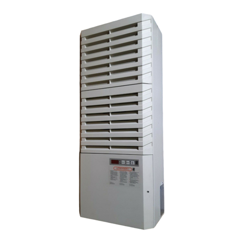
Rittal LCU CW User manual

Liquid cooling unit LCU CW
3313.610
Assembly and operating instructions

EN
2Rittal Liquid Cooling Unit LCU CW
Foreword
Foreword
Dear Customer,
Thank you for choosing a Rittal Liquid Cooling Unit (also
referred to hereafter as "LCU CW").
Please take the time to read this documentation carefully
and pay particular attention to the safety instructions in
the text and to section 2 "Safety instructions".
This is the prerequisite for:
– secure assembly of the LCU CW
– safe handling and
– the most trouble-free operation possible.
Please keep the complete documentation readily avail-
able so that it is always on hand when needed.
We wish you every success!
Your,
Rittal GmbH & Co. KG
Rittal GmbH & Co. KG
Auf dem Stützelberg
35745 Herborn
Germany
Tel.: +49(0)2772 505-0
Fax: +49(0)2772 505-2319
E-mail: info@rittal.de
www.rittal.com
www.rittal.de
We are always happy to answer any technical questions
regarding our entire range of products.

EN
Rittal Liquid Cooling Unit LCU CW 3
Contents
Contents
1 Notes on documentation .................. 4
1.1 LCU CW ....................................................... 4
1.2 Storing the documents.................................. 4
1.3 Symbols in these operating instructions ........ 4
1.4 Other applicable documents ......................... 4
1.5 Normative instructions .................................. 4
1.5.1 Legal information concerning the operating
instructions ........................................................... 4
1.5.2 Copyright ............................................................. 4
1.6 Validity .......................................................... 4
2 Safety instructions ............................ 5
2.1 General safety instructions ............................ 5
2.2 Safety instructions for transportation ............. 5
2.3 Safety instructions for assembly.................... 5
2.4 Safety instructions for installation .................. 5
2.5 Safety instructions for operation.................... 5
2.6 Safety instructions for maintenance............... 6
2.7 Safety instructions on shutting down............. 6
2.8 Operating and technical staff......................... 6
2.9 Personal protective equipment...................... 6
2.10 RoHS compliance......................................... 6
3 Product description .......................... 7
3.1 General functional description ....................... 7
3.2 Control modes.............................................. 7
3.2.1 General information .............................................. 7
3.2.2 Automatic mode ................................................... 7
3.3 Ambient conditions ....................................... 8
3.4 Air routing ................................................... 10
3.4.1 General .............................................................. 10
3.5 Proper and improper usage ........................ 10
3.6 Supply scope.............................................. 10
4 Transportation and handling ........... 11
4.1 Transportation ............................................ 11
4.2 Unpacking .................................................. 11
5 Assembly and siting ....................... 13
5.1 Installation site requirements ....................... 13
5.2 Installing the LCU CW in a VX IT
server rack .................................................. 13
5.3 Positioning the pressure sensors................. 15
6 Installation ...................................... 16
6.1 Electrical connection ................................... 16
6.2 Cooling water connection ........................... 17
7 Configuration ................................. 20
7.1 General ....................................................... 20
7.2 HTTP connection ........................................ 20
7.2.1 Making the connection ....................................... 20
7.2.2 Changing the network settings ........................... 20
7.2.3 Changing the measurement units ....................... 21
7.2.4 LCU CW configuration ........................................ 21
7.2.5 Settings .............................................................. 25
8 Operation ....................................... 26
8.1 Control unit for the LCU CW....................... 26
8.2 Display ....................................................... 26
8.2.1 General information about programming ............ 27
8.2.2 Setting the unit ................................................... 27
8.2.3 Manually acknowledge a system message ......... 28
8.2.4 Rittal Scan & Service app ................................... 28
8.3 Description of operation ............................. 28
8.3.1 General .............................................................. 28
8.3.2 Acknowledging messages .................................. 28
8.4 Extended options by connecting the
LCU CW to a network ................................ 29
8.5 General operation ...................................... 29
8.5.1 Layout of screen pages ...................................... 29
8.5.2 Navigation area in left-hand section .................... 29
8.5.3 Index tabs in the configuration area .................... 30
8.5.4 Message display ................................................. 30
8.5.5 Other displays .................................................... 31
8.5.6 Changing parameter values ................................ 31
8.5.7 Logging off and changing the password ............. 32
8.5.8 Reorganising the connected components .......... 33
8.6 Monitoring index tab .................................. 33
8.6.1 Device ................................................................ 33
8.6.2 Air Temp ............................................................ 33
8.6.3 Fans ................................................................... 34
8.6.4 Coolant .............................................................. 35
8.6.5 Valve .................................................................. 36
8.6.6 Cooling Capacity ................................................ 36
8.6.7 Leakage Sensor ................................................. 37
8.6.8 Setup ................................................................. 37
8.7 Configuration index tab .............................. 40
8.8 Tasks ......................................................... 40
9 Updates and data backup .............. 42
10 Troubleshooting ............................. 43
10.1 General faults ............................................. 43
10.2 System messages...................................... 45
11 Inspection and maintenance ........... 47
12 Storage and disposal ...................... 48
13 Technical specifications .................. 49
13.1 General technical specifications ................. 49
13.2 Cooling capacity ........................................ 49
13.3 Water side pressure loss ............................ 51
13.4 P&ID scheme ............................................. 52
13.5 Circuit diagram........................................... 53
14 Information concerning the filling
and additive water .......................... 63
15 Spare parts .................................... 64
16 Accessories .................................... 65
17 Glossary ......................................... 66

4Rittal Liquid Cooling Unit LCU CW
1 Notes on documentation
EN 1 Notes on documentation
1.1 LCU CW
The Liquid Cooling Unit, hereafter referred to as the
LCU CW, boasts a range of different approvals, details
of which can be found on the Rittal website.
Installation and maintenance must only be carried out by
qualified personnel.
1.2 Storing the documents
The assembly and operating instructions as well as all
applicable documents are integral components of the
product. They must be handed out to those persons
who are engaged with the unit and must always be avail-
able and on hand for operating and maintenance per-
sonnel.
1.3 Symbols in these operating instructions
The following symbols are found in this documentation:
This symbol indicates an "action point" and shows that
you should perform an operation or work step.
1.4 Other applicable documents
In conjunction with these assembly and operating in-
structions, the superordinate system documentation (if
available) also applies.
Rittal GmbH & Co. KG is not responsible for any damage
which may result from failure to comply with these as-
sembly and operating instructions. The same applies to
failure to comply with the valid documentation for acces-
sories used.
1.5 Normative instructions
1.5.1 Legal information concerning the operating
instructions
We reserve the right to make changes in content. Rittal
GmbH & Co. KG will not be held liable for any mistakes
in this documentation. Liability for indirect damages
which occur through the delivery or use of this docu-
mentation is excluded to the extent allowable by law.
1.5.2 Copyright
The distribution and duplication of this document and
the disclosure and use of its contents are prohibited un-
less expressly authorised.
Offenders will be liable for damages. All rights created by
a patent grant or registration of a utility model or design
are reserved.
1.6 Validity
These Operating Instructions only apply to the LCU CW.
Danger!
Hazardous situation which will result in
death or serious injury if the instructions
are not followed.
Warning!
Hazardous situation which may lead to
death or serious injury if the instructions
are not followed.
Caution!
Hazardous situation which may lead to
(minor) injuries if the instructions are not
followed.
Note:
Information concerning individual proce-
dures, explanations, or tips for simplified ap-
proaches. Also indicates situations which
may result in material damage.

Rittal Liquid Cooling Unit LCU CW 5
2 Safety instructions
EN
2 Safety instructions
The LCU CW produced by Rittal GmbH & Co. KG are
developed and produced by Rittal with due regard to all
safety precautions. Nevertheless, the unit still causes a
number of unavoidable dangers and risks. The safety in-
structions provide you with an overview of these dan-
gers and the necessary safety precautions.
In the interest of your safety and the safety of others,
please read these safety instructions carefully before as-
sembly and commissioning of the LCU CW.
Follow the user information found in these instructions
and on the unit carefully.
2.1 General safety instructions
Please observe the following general safety instructions.
Always wear the required personal protective equip-
ment when working on this device (see section2.9
"Personal protective equipment").
Please do not make any changes to the LCU CW that
are not described in these operating instructions or
other applicable assembly and operating instructions.
The LCU CW should only be combined and operated
with the prescribed Rittal system accessories.
Other than these general safety instructions, it is also
vital to observe the specific safety instructions when
carrying out the tasks described in the following chap-
ters.
– Danger of injury from electric shock if the unit is
opened while connected to the mains. The unit must
only be opened and repaired by trained specialists or
qualified individuals.
2.2 Safety instructions for transportation
– There is a risk of injury from falling loads. Do not stand
under suspended loads when transporting the unit
with a hoist trolley, a forklift, or a crane. Be sure to use
an appropriate means of transport.
– There is a risk of injury when cutting through the pre-
tensioned tightening straps. Wear personal protective
equipment (PPE)!
– There is a risk of injury due to the heavy weight of the
device. Please observe the maximum permissible
weight to be lifted by one person. Use suitable lifting
devices, if needed.
2.3 Safety instructions for assembly
– Have the devices installed by qualified specialists
trained by Rittal.
– Beware of injuries if the unit tips over. From a horizon-
tal position, the unit should always be set upright by
two people working together, with one person bracing
the unit to prevent it from slipping as it is lifted. Wear
personal protective equipment (PPE)!
– There is a risk of injury from the device tipping over.
While upright, the LCU CW is at risk of toppling over
until it installed and correctly secured inside the server
rack. The second person should hold the unit securely
in an upright position until this has been done.
– While inserting the unit into the server rack, there is a
danger of crushing between the outer edges of the
unit and the frame section of the rack. Wear personal
protective equipment (PPE)!
2.4 Safety instructions for installation
– There is a risk of crushing when the containment sys-
tem is inserted into the server enclosure. Wear per-
sonal protective equipment (PPE)!
– There is a risk of becoming trapped and cut when
screwing on and sealing the coolant lines. Wear per-
sonal protective equipment (PPE)!
– Following installation, ensure that the coolant lines do
not restrict the flow of air through the device.
– Work on electrical systems or equipment may only be
carried out by an electrician or by trained personnel
guided and supervised by an electrician. All work must
be carried out in accordance with electrical engineer-
ing regulations.
– Use only insulated tools. Wear personal protective
equipment (PPE)!
– The voltage values shown in the wiring plan or on the
rating plate must match the mains voltage.
– Incorrect assembly and installation may lead to the risk
of condensation forming in the device, which can lead
to an electrical short circuit or to leaks of liquid.
2.5 Safety instructions for operation
– Risk of malfunction or damage! Do not modify the unit!
Use only original spare parts!
– There may be an increased noise level when the LCP
is in operation, especially when the device is operated
directly on the display. Wear personal protective
equipment (PPE)!
– Proper and flawless unit operation can only be en-
sured when it is operated under the intended ambient
conditions. As far as possible, be sure that the ambi-
ent conditions for which the unit is designed are com-
plied with, e.g. temperature, humidity, air purity.
– The medium necessary for the control system, i.e.
cooling water, must be available throughout the entire
operating time.
– If leaks occur, there is the risk of injury caused by es-
caping refrigerant, in particular glycol. Wear personal
protective equipment, collect any escaped refrigerant
with suitable cloths or absorbent materials, and rectify
the leakage cause without delay.
– The leak sensor built into the unit is for functional leak
detection only and should not be used as part of a
safety chain system.
– Injury caused by fan impellors! Keep persons and ob-
jects away from the fan impellors! Do not remove cov-
ers until the power supply is disconnected and impel-
lors are not moving! Always use mechanical protection
when working! Shut down the respective fan during

6Rittal Liquid Cooling Unit LCU CW
2 Safety instructions
EN
maintenance work, if possible! Tie long hair back! Do
not wear loose clothing! Fans start up automatically
following power disruptions!
2.6 Safety instructions for maintenance
– The unit must be safely disconnected from the power
supply before carrying out any maintenance work or
troubleshooting inside the unit. Either pull the connec-
tor from the mains or use the all-pole disconnector in
the supply lead and secure against unintentional reac-
tivation.
– In particular, the sharp edges of the heat exchanger
module may cut and cause injury while working on the
unit. Put on personal protective equipment before be-
ginning assembly or cleaning work!
– When removing and installing a fan module, injuries
may potentially be caused by the sharp edges inside
the LCU CW, or if the module is dropped, or as a result
of high air speeds and noise. Wear personal protective
equipment (PPE)!
– Always read the relevant safety data sheet when work-
ing with the cooling medium.
2.7 Safety instructions on shutting down
– Laypeople are not qualified to ensure the required
shutdown procedures. This work must only be carried
out by qualified, trained experts.
– During storage and transportation below freezing
point, the water circuit should be drained completely
using compressed air!
2.8 Operating and technical staff
The installation, commissioning, maintenance and repair
of this unit may be performed only by qualified special-
ists trained by Rittal.
Only properly instructed personnel may perform service
on a unit while in operation.
– Never allow the unit to be used by people (or children)
with limited physical, sensory or mental abilities or in-
sufficient knowledge and experience, unless super-
vised or properly instructed.
– Children must be supervised and never allowed to play
with the unit.
2.9 Personal protective equipment
Personal protective equipment, which should as a mini-
mum include waterproof protective gloves and safety
goggles, must be worn during any work on the unit
when personnel might come into contact with refrigerant
(for deployment of a water-glycol mixture).
We also recommend the wearing of suitable ear muffs
and a hair net when working near the unit.
For all work on the LCU CW, in particular on the outlet
side, wearing safety goggles is recommended to pre-
vent eye injuries caused by the high air speeds.
2.10 RoHS compliance
The LCU CW fulfils the requirements of EU directive
2011/65/EC on the Restriction of Use of Certain Hazard-
ous Substances in Electrical and Electronic Equipment
(RoHS 2) of 08 June, 2011.
Safety notice according to Regulation (EC) No.
1907/2006
The product contains the following SVHC substances:
According to the manufacturer, there are no health risks
if the product is used properly.
After use, the product must be properly disposed of in
accordance with the applicable legal regulations.
Note:
Corresponding information concerning the
RoHS directive is provided by our firm on the
Internet at www.rittal.com/RoHS.
SVHC substance CAS No.
4,4'-isopropylidenediphenol 80-05-7
Lead 7439-92-1
Cadmium 7440-43-9
Mercury 7439-97-6
Lead titanium trioxide 12060-00-3
Lead monoxide (lead oxide) 1317-36-8
Diboron trioxide 1303-86-2
Tab. 1: SVHC substances

Rittal Liquid Cooling Unit LCU CW 7
3 Product description
EN
3 Product description
3.1 General functional description
The LCU CW is essentially an air/water heat exchanger
that is used to dissipate high heat losses from server en-
closures or for the effective cooling of devices built into
a server enclosure.
The air routing in the LCU CW supports the "front to
back" cooling principle of the devices built into the server
enclosure. The hot air expelled by the devices in the
server enclosure is drawn in by the fans and thus routed
through the heat exchanger module.
In the heat exchanger module, the heated air is directed
through an air/water heat exchanger, and its thermal en-
ergy (heat losses from the server) is transferred to a cold
water system. As a result, the air is cooled to a freely se-
lectable temperature within the authorised parameters
and then routed directly in front of the 482.6 mm (19")
level in the server enclosure.
3.2 Control modes
3.2.1 General information
The LCU CW can be operated in various control modes
depending on the deployment condition:
– Automatic mode: The server inlet temperature (cold
air) serves as a reference variable. The water flow and
the fan speed are controlled to provide the required
cooling capacity.
– Manual control: The water flow and the fan speed are
specified manually. The set parameters serve as refer-
ence variables.
3.2.2 Automatic mode
The temperature of the cold air intake is controlled via
constant comparison of the actual temperature with the
setpoint temperature set on the LCU CW (default is
+24 °C).
If the server-in temperature exceeds the setpoint tem-
perature, the control valve in the cooling water system
opens (linear opening from 0 – 100%), and the heat ex-
changer is supplied with cold water.
Fig. 1: Opening degree of the control valve
If the difference "server inlet temperature – setpoint val-
ue"
– is less than 0: the control valve is further closed.
– is greater than 0: the control valve is further opened.
– is equal to 0: the control valve retains its opening
degree.
The temperature differential between the setpoint and
the warm air that is drawn is used to determine and set
the fan speed. The control unit attempts to keep the air
temperature constant in front of the 482.6 mm (19") level
(LCP Rack) by activating the control valve.
Fig. 2: Fan control
– The lower limit of the Delta-T value can be set in the
range between 0 K…20 K.
– The upper limit of the Delta-T value can be set in the
range between 3 K…40 K.
– The lower speed value can be set in the range be-
tween the minimum speed and 80% of the maximum
speed.
Optional: Fan speed control according to the pres-
sure difference
If the fan speed is controlled according to the pressure
difference, the pressure in front of and behind the server
rack's built-in devices is ascertained and compared with
the set pressure difference to calculate the fan speed.
Note:
The water inlet temperature must always be
chosen (controlled) so that it always lies
above the dew point for the prevailing ambi-
ent temperature and humidity in the data
centre. The dew point can be found in the
Mollier h-x diagram (fig. 3).
Furthermore, we advise compliance with the
ASHRAE standard "ASHRAE TC 9.9, 2011
Thermal Guidelines for Data Processing Envi-
ronments".
Note:
Rittal cannot accept any liability for damage
and consequential damage caused by im-
proper parameter settings.
100%
19%
0º 90º
Water flow
Opening degree
15 K 20 K5 K Δ
T
100%
Fan speed
Minimum
speed

8Rittal Liquid Cooling Unit LCU CW
3 Product description
EN
3.3 Ambient conditions
The LCU CW is used to dissipate the thermal load gen-
erated by IT equipment and prevent the installation site
of the IT equipment from overheating. If IT systems are
operated at excessive ambient temperatures, this may
lead to malfunctions and restricted operation of the sys-
tem. The correct system temperature is based on man-
ufacturer-specific information.
Based on the prescribed conditions, please use the Mol-
lier h-x diagram to check whether cooling at the pre-
scribed cold water temperature will fall below the dew
point (fig. 3 "Mollier h-x diagram for humid air").
The blue markings in the Mollier h-x diagram give an ex-
ample of how to calculate the dew point for the following
conditions:
– Room temperature: 22 °C
– Relative humidity: 50%
This produces a dew point of 11 °C.
Sensitive and latent cooling output
If the surface temperature of the heat exchanger in the
LCU CW is below the dew point, condensation will form
on the heat exchanger. This leads to cooling capacity
losses, because the energy is sometimes used for con-
densation (latent cooling capacity).
If, however, when working with cold water temperatures
where the surface temperature of the heat exchanger is
above the dew point, the energy is used only to cool the
server supply air (sensitive cooling capacity).
Section6.2 "Cooling water connection" describes a
tried-and-tested hydraulic circuit which quickly and eas-
ily supplies the required volume of water at the correct
temperature.
Note:
By default, the fan is controlled according to
the temperature difference.
Note:
ASHRAE (American Society of Heating, Re-
frigerating and Air-Conditioning Engineers)
recommends server intake air temperatures
of between 18 °C and 27 °C. The selected
server intake air temperature should be
agreed with the manufacturer of the IT equip-
ment and the operator at the project planning
stage.
Note:
To obtain support, contact Rittal.

Rittal Liquid Cooling Unit LCU CW 9
3 Product description
EN
Fig. 3: Mollier h-x diagram for humid air
1.25 kg/m3
1.20 kg/m3
1.15 kg/m3
1.10 kg/m3
1.05 kg/m3
0 kJ/kg
20 kJ/kg
40 kJ/kg
60 kJ/kg
Enthalpy
100%
50%
90%
80%
70%
60%
40%
30%20%15%10%5%
Rel. Humidity
0 g/kg
2 g/kg
4 g/kg
6 g/kg
8 g/kg
10 g/kg
12 g/kg
14 g/kg
16 g/kg
18 g/kg
20 g/kg
Water
-15º
-10º
-5º
0º
5º
10º
15º
20º
25º
30º
35º
40º
Temperature
Mollier h-x diagram for humid air – pressure 0.950 bar (537.000 m / 10.000ºC / 80.000% rF)
22º
11º
Dew point curve

10 Rittal Liquid Cooling Unit LCU CW
3 Product description
EN
3.4 Air routing
3.4.1 General
In order to achieve sufficient cooling in the server enclo-
sure, it is important to ensure that the cooling air passes
through the interior of the built-in units and is unable to
flow past at the sides.
Targeted air routing in the server enclosure has a major
effect on the heat loss to be dissipated.
In order to ensure targeted air routing in the system, the
server enclosure should be divided vertically into warm
air and cold air sections. The division is accomplished in
the front section of the server assembly to the left and
right of the 482.6 mm (19") level using foam strips or air
baffle plates which, depending on the enclosure width
and the number of server enclosures to be cooled, can
be ordered as an accessory.
3.5 Proper and improper usage
The LCU CW is an air/water heat exchanger that cools
closed spaces or housings in which IT components,
such as servers, switches or similar, are installed and are
used in a technology room or data centre.
LCUs must always be used in conjunction with a cold-
water supply, typically chiller or free-cooler. The water
supply must always be a closed circuit. The water quality
during the complete service life must conform with the
details in these instructions.
The unit may be deployed only within the technical op-
erational limits as described in these instructions.
The unit is state of the art and built according to recog-
nised safety regulations. Nevertheless, improper use
can present a hazard to life and limb of the user or third
parties, or result in possible damage to the system and
other property.
Consequently, the unit must only be used properly and
in a technically sound condition.
Any malfunctions which impair safety should be rectified
immediately. Follow the operating instructions!
Proper use also includes following the operating instruc-
tions and fulfilling the inspection and maintenance con-
ditions.
Inappropriate use may result in danger. Inappropriate
use may include:
– Use of impermissible tools.
– Improper use.
– Improper rectification of malfunctions.
– Use of replacement parts which are not authorised by
Rittal GmbH & Co. KG.
– Failure to observe the required water quality.
– Use of a coolant other than water.
– Expelling the cold air into an air duct system.
– Use in an industrial environment.
– Non-stationary use, e.g. on moving or vibrating ma-
chines.
– Continuous operation below the dew point.
– Operation as air conditioning for humans.
– Operation as food cooling.
– Provision of the units in publicly accessible areas.
– Violation of the permitted electrical voltage ranges.
3.6 Supply scope
The LCU CW supply includes:
Note:
The 482.6 mm (19") level must likewise be
completely sealed. This is already the case in
a fully equipped server enclosure. If the serv-
er enclosure is partially equipped, the open
height units (U) of the 482.6 mm (19") level
must be sealed with blanking plates, which
are available as Rittal accessories.
As more devices are installed in the server
enclosure, it becomes even more important
to follow this specification.
Qty. Parts
1 Liquid Cooling Unit CW
1 Dispatch bag:
1 Support for LCU CW
1 Condensate discharge hose (3 m)
2 Angular hose connector 90°
12 Screw M5 x 12, self-tapping NZ/TX30
1 7-pole female connector
1 Assembly and operating instructions
Tab. 2: Supply scope

Rittal Liquid Cooling Unit LCU CW 11
4 Transportation and handling
EN
4 Transportation and handling
4.1 Transportation
The LCU CW is delivered shrink-wrapped on a pallet.
Because of its heavy weight, never lift the LCU CW by
yourself (or even together with several people). Always
use appropriate lifting gear.
4.2 Unpacking
Remove the separate lid from the wooden box.
Fig. 4: Removing the separate lid
Remove the packaging materials and lift out the ac-
cessories.
Fig. 5: Removing the packaging materials and accessories
Key
1 Packaging materials
2 Accessories
With two people holding the device by the handles, lift
it up.
Fig. 6: Lifting the device
Take care not to rest or set the device down on the
water connections at the rear.
Fig. 7: Water connections on the rear of the device
Pull the device forwards slightly and set down on the
edge of the wooden packaging.
Caution!
Risk of injury during transport and when
handling the unit.
Wear your personal protective equip-
ment for the work described below.
Caution!
Transport of the LCU CW:
Use only suitable and technically sound
lifting gear and load-bearing devices
with sufficient load capacity.
Caution!
There is a risk of crushing when remov-
ing the LCU CW from its wooden pack-
aging.
1112

12 Rittal Liquid Cooling Unit LCU CW
4 Transportation and handling
EN
Fig. 8: Setting down the device
With two people at the end faces, grasp hold of the
device from beneath and remove it from the packag-
ing.
Set the LCU CW down vertically on its underside and
protect it from tipping over.
Check the unit for any damage that may have oc-
curred during transport.
Note:
After unpacking, the packaging materials
must be disposed of in an environmentally
friendly way. They are comprised of the fol-
lowing materials:
Wood, polyethylene film (PE film), strap, edge
protectors, cardboard.

Rittal Liquid Cooling Unit LCU CW 13
5 Assembly and siting
EN
5 Assembly and siting
5.1 Installation site requirements
The LCU CW is an air/water heat exchanger for IT equip-
ment.
Please observe the following general remarks on the in-
stallation site:
– The installation site of the LCU CWs must be ade-
quately protected from external weather conditions.
– Please follow the standard code of practice when po-
sitioning.
– If the intake air to the installation room is cooled by an
air-conditioning system, be sure to tailor the relative air
humidity to the water inlet temperature of the
LCU CWs. This avoids condensation and ensures
maximum energy efficiency (see section3.3 "Ambient
conditions").
– The unit must not be located or operated at sites ac-
cessible to the general public. Only appropriately au-
thorised personnel should have access to the installa-
tion site.
– The cabinet housing the LCU CW must be easily ac-
cessible from the front and rear, with at least 0.8 m x
1 m (width x depth) of free space in front of the cabi-
net.
– The maximum altitude at which the LCU CW may be
operated is 2000 m above sea level.
In order to ensure problem-free operation of the
LCU CW, the following conditions for the installation lo-
cation should be observed:
Supply connections required at the installation site
per LCU CW
5.2 Installing the LCU CW in a VX IT server
rack
The internal unit may be mounted both on the right and
on the left of the VX IT server rack.
Before the internal unit of the LCU CW can be installed
in a VX IT server rack, the following work should be car-
ried out:
Slide the 482.6 mm (19") mounting angles away from
you by 50 mm.
Fig. 9: 482.6 mm (19") mounting angle pushed away
Position the front 482.6 mm (19") level in position 7to
carry out air blocking with the recommended acces-
sories.
Fig. 10: Positioning the 482.6 mm (19") level
Position one punched section with mounting flange at
the very bottom and one at the very top of the rack.
Secure it to the inner level of the VX frame (mounting
side).
– VX punched section with mounting flange 23 x
64 mm for enclosure depth 1000 mm: 8617.150,
1pack=4pcs.
– VX punched section with mounting flange 23 x
64 mm for enclosure depth 1200 mm: 8617.160,
1pack=4pcs.
Type of connection Connection description
Power connection: 230 V, 1~, 50/60 Hz
Coolant connection: Max. permitted operating pres-
sure PS = 10 bar
Tab. 3: Supply connections required at the installation site
Note:
Please see the notes and data regarding the
cold water connection in section6.2 "Cool-
ing water connection".
Note:
The illustration below shows installation on
the left-hand side of the VX IT server rack.
123456
1
3
5
7

14 Rittal Liquid Cooling Unit LCU CW
5 Assembly and siting
EN
Fig. 11: Bottom punched section with mounting flange
Fig. 12: Top punched section with mounting flange
Secure the rail for mounting the LCU CW right at the
front of the bottom punched section with mounting
flange (see fig. 13).
Using the two brackets at the front and rear, secure
the mounting rail to the bottom punched section with
mounting flange with 2 screws.
Please observe the following distances between the
front edge of the VX frame and the front edge of the
mounting rail:
Minimum 130 mm.
For the 1000 mm deep VX IT rack max. 150 mm
For the 1200 mm deep VX IT rack max. 160 mm
Fig. 13: Front fastening of the rail
Key
1 Fastening screws
2 Mounting rail
The above spacings ensure sufficient space at the front
of the device for the expelled air, and sufficient space at
the rear of the device for the various connections.
Position the LCU CW on the mounting rail.
Screw the LCU CW onto the top punched section with
mounting flange using the brackets provided.
Note:
If the LCU CW is installed in a different net-
work/server rack, the distance between the
front edge of the rack frame and the air outlet
of the LCU CW should be at least 130 mm.
Caution!
There is a risk that the LCU CW might tip
over.
Protect the LCU CW from tipping over
until it is securely attached to the top
punched section with mounting flange.
12

Rittal Liquid Cooling Unit LCU CW 15
5 Assembly and siting
EN
Fig. 14: Securing the LCU CW to the front at the top
Key
1Fasteningscrews
2LCU
5.3 Positioning the pressure sensors
For fan speed control according to the pressure differ-
ence, you will additionally need at least one or a maxi-
mum of two differential pressure sensors (7030.150).
These are available as Rittal accessories.
Fit the differential pressure sensor in the rack as de-
scribed in the instructions enclosed with the sensor.
When fitting the air hoses, be careful not to position
the two measurement points for reference pressure
and comparison measurement in a direct airflow.
Connect the pressure sensor to the CAN bus connec-
tion of the climate controller (see fig. 29).
The sensor is then managed under "Real Devices" in the
selection tree on the LCU CW website.
Note:
Take care to ensure that air routing in the air
intake and outlet zone of the LCU CW is not
obstructed by other installed components.
12

16 Rittal Liquid Cooling Unit LCU CW
6 Installation
EN 6 Installation
During the installation of the unit, the personal protective
equipment, consisting of at least waterproof protective
gloves and safety goggles, must be worn.
6.1 Electrical connection
The LCU CW is electrically connected using the type
C14 connector.
Fig. 15: Connections in the rear top area
Key
1 IEC 60320 type C14 connector with lock plate
2 ON/OFF button
3 2 network connections
4 Connection cable: Earthing pin / C13 socket
Remove the screw from the connector lock plate.
Fig. 16: Securing the lock plate
Key
1 Screw
2 Connector lock plate
Gently push the lock plate downwards and then pull it
off backwards.
Note:
Please keep this electrical documentation
readily available so that it is always on hand
when needed. This is the only documentation
which is authoritative for the unit.
Caution!
Work on electrical systems or equip-
ment may only be carried out by an elec-
trician or by trained personnel guided
and supervised by an electrician. All
work must be carried out in accordance
with electrical engineering regulations.
The unit may only be connected after the
above-named personnel have read this
information.
Use only insulated tools.
Wear personal safety equipment.
The connection regulations of the ap-
propriate electrical power company are
to be followed.
The voltage values shown in the wiring
plan or on the rating plate must match
the mains voltage.
The pre-fuse specified in the wiring plan/
rating plate should be provided to pro-
tect the cable and equipment from
short-circuits. The unit must be individu-
ally fused.
No additional control equipment may be
connected upstream of the device at the
supply end.
34
12
1
2

Rittal Liquid Cooling Unit LCU CW 17
6 Installation
EN
Fig. 17: Removing the lock plate
Connect the cable, which is included in the scope of
delivery with the C13 jack to the device connector.
Re-attach the lock plate over the C13 jack and the
connection cable and secure with the screw.
6.2 Cooling water connection
The LCU CW is connected to the cold water network via
two G¾" threaded pipe connections (external thread) on
the inlet and return.
Fig. 18: Cooling water connection
In case of a low water inlet temperature, the inlet and re-
turn lines should be appropriately insulated. If this is not
done, condensate may form on the supply lines.
General remarks on the cold water system
IT climate control poses a major challenge for the cold
water system, because the IT equipment whose heat
loss is to be dissipated by the cold water system can un-
dergo multiple load changes per minute. This hysteresis
is transferred directly to the cold water system, leading
to a fluctuating ΔT. If this causes a major load step, lead-
ing to a rapid increase in heat loss, cold water must be
made available immediately by the cold water system.
Depending on the distance of the cooling unit from the
IT cold water circuit, this can create a significant dead
time during which no water is available to cool the IT
heat loss.
Because of hysteresis induced by the IT equipment, ΔT
fluctuations in the cold water circuit are unavoidable.
Fluctuations of between 1 K and 10 K are not uncom-
mon in IT climate control. For this reason, the usual ΔT
of 6 K for a cold water circuit cannot be used to calculate
the pipework. In the case of LCU CW, the volumetric
flow required for the rated cooling output is always spec-
ified. With this volumetric flow, the correct pipe dimen-
sions can be selected when calculating the pipework.
Example of an injection circuit
Fluctuations in the ΔT in the cold water circuit can be
compensated using an hydraulic circuit. For example, by
assembling an injection circuit, the cold water system is
able to counteract the hysteresis generated by the IT
equipment.
With the injection circuit, the primary circuit is installed as
close as possible to the secondary circuit. The second-
Note:
The cooling water connection must always
be made with union nuts
Caution!
When installing, observe the applicable
specifications concerning water quality
and water pressure.
Note:
Any on-site pipework with multiple LCUs on
one water circuit should include a flow regu-
lator to adjust the flow rate of each LCU CW.
Ideally, the LCU CWs are connected to the
cooling water circuit via a water/water heat
exchanger when using a water/glycol mix-
ture.
Pros:
– Reduction of water volumes in the second-
ary circuit,
– Setting of a defined water quality,
– Setting of a defined input temperature and
– Setting of a defined volumetric flow.

18 Rittal Liquid Cooling Unit LCU CW
6 Installation
EN
ary circuit is assembled in the immediate vicinity of the
equipment. The cold water is able to circulate perma-
nently in the primary circuit, and is therefore always avail-
able when needed by the secondary circuit. Without this
circuit, the cold water would first need to cover the entire
distance from the producer to the equipment whenever
the flow rate is altered by the equipment. Here too, there
may be a significantly lower temperature in the primary
circuit than in the secondary circuit, e.g. 6 °C in the pri-
mary circuit and 15 °C in the secondary circuit as a re-
sult of mixing.
In this way, the primary circuit pump 1 permanently pro-
vides the secondary circuit with water. The mixer valve
in the return limits the volume of water flowing out of the
secondary circuit and back into the primary circuit. This
therefore limits the incoming water volume as well. The
secondary circuit pump allows the entire volume of wa-
ter required for cooling in the secondary circuit to circu-
late, and is responsible for mixing the temperatures.
Pump 2 allows water from the secondary return to be
"injected" into the secondary inlet via the bypass. In this
way, cold water from the primary circuit is raised directly
to the correct temperature level. The injection circuit is
just one example of many possibilities for adapting the
cold water system to the requirements of IT climate con-
trol.
Fig. 19: Injection circuit (layout diagram)
In the LCU CW, a sensor built into the upstream end
measures the water flow rate without any moving com-
ponents. The measurement range of this flow meter is
between 2 l/min and 40 l/min.
If the server racks are initially only equipped with minimal
IT equipment, or if operating at low water inlet tempera-
tures (e.g. 10 °C), the flow rate will be low. If this flow rate
falls below the aforementioned limits, this may lead to
system warnings from the flow meter. These warnings
may be deactivated by configuring the parameters "Sys-
tem Warning min. Flow" and "System Warning min.
Valve" (see section7.2.4 "LCU CW configuration")
Alternatively, the occurrence of such error messages
can also be avoided by using the injection circuit. To this
end, the supplied cooling water from the primary and
secondary circuit must be mixed differently to create a
higher inlet temperature.
Hydraulic balancing
For an efficient cold water supply to the LCU CW, the
cold water system must be hydraulically balanced. If the
hydraulics are not balanced, the LCU systems will not be
supplied homogeneously with the required volume of
cold water. This will adversely affect efficient operation.
Fig. 20: Cooling distribution without hydraulic balancing
Key
1 Circulating pump
2 Shut-off valve
3 Fine filter
4Return
5Inlet
6 Pump pressure
7 Cooling supply
8 Opening degree of control valve
9 Control valve
Here, hydraulic balancing can be achieved via circuit
control valves.
LCU
LCU
LCU
LCU
1
2
Bypass line
30%30%
70%
30%
70%
30%
100% 100%
100% 100%
1
30
%
3
0
%
1
00
%
"Circuit 2"
"Circuit 1"
15°C
1
4
5
6
7
2
3

Rittal Liquid Cooling Unit LCU CW 19
6 Installation
EN
Fig. 21: Cooling distribution with hydraulic balancing
Note:
Before commencing operation with water, all
supply lines must be adequately flushed.
Note:
To avoid the loss of fluids due to diffusion for
closed systems, it is recommended to deploy
automatic filling with conditioned additive wa-
ter.
Note:
The 2-way control valve used in the device is
opened at zero current.
15°C
1
4
5
6
7
2
3
8
9

20 Rittal Liquid Cooling Unit LCU CW
7 Configuration
EN 7 Configuration
7.1 General
Basic configuration of the LCU CW, particularly the (one-
off) adjustment of the network settings, may be carried
out in various ways:
1. HTTP connection via the Ethernet interface
2. Telnet/SSH connection via the Ethernet interface
3. Serial connection via a USB cable
The settings are generally made via an HTTP connec-
tion. If this is not possible, for example because access
via HTTP or HTTPS has been deactivated, we recom-
mend access via a Telnet/SSH connection. To this end,
as with access via an HTTP connection, the IP address
of the climate controller integrated into the LCU CW
must be known. If this address is not known, the device
may be accessed directly via the USB-C/serial interface.
The following descriptions assume that the LCU CW,
and in particular the climate controller, are in their deliv-
ered state, i.e. that no changes have been made to the
basic configuration. In particular, the connection types
"HTTP" and "Telnet/SSH" must not be blocked.
7.2 HTTP connection
7.2.1 Making the connection
Using a network cable, connect the device to your
computer via the Ethernet interface (fig. 15, item 3).
Change your computer's IP address to any address
within the range 192.168.0.xxx, e.g. 192.168.0.191.
The device's preset address 192.168.0.190 must not
be used.
Set the subnet mask to the value 255.255.255.0.
If applicable, switch off the proxy server in the browser
to facilitate a direct connection to the device.
In the browser, enter the address
http://192.168.0.190. The log-on dialogue for regis-
tering the device will appear.
Fig. 22: Log-on screen with an HTTP connection
Log in with the username admin and the password
admin (fig. 22, item 1).
The overview window for the device will appear (fig. 23).
7.2.2 Changing the network settings
As a general rule, during the course of commissioning,
the network settings of the climate controller will only
need to be changed once, so that it is linked into your
network structure.
In the left-hand section of the overview window (navi-
gation area), click on the Processing Unit entry
(fig. 23, item 3) and in the right-hand section (configu-
ration area), click on the Configuration tab (fig. 23,
item 4).
Fig. 23: Adjusting the TCP/IP settings
In the group box Network, click on the TCP/IP button
(fig. 23, item 5).
Fig. 24: Adjusting the TCP/IP settings
In the TCP/IP Configuration window, change the
device's IP address in the IPv4 Configuration group
box to an address permitted in the network (fig. 24).
If necessary, correct the settings for the subnet mask
and the gateway.
Note:
Depending on your computer, you may need
to use a crossover cable.
1
Note:
The following sections describe in detail how
to make the setting for the IPv4 protocol. Fur-
ther notes regarding the TCP/IP configura-
tion are contained in the assembly and
operating instructions for the IoT Interface
3124.300.
4
3
5
This manual suits for next models
1
Table of contents
Other Rittal Computer Hardware manuals
Popular Computer Hardware manuals by other brands
Dantel
Dantel 46020-41 Installation & operation manual
NXP Semiconductors
NXP Semiconductors i.MX 8M quick start guide

Hydraram
Hydraram MK Series Operation and maintenance manual
Panasonic
Panasonic CF-BAW0512AU operating instructions
Mylex
Mylex eXtremeRAID Quick installation guide

Stahl
Stahl IS1+ 9440/15 Series operating instructions

