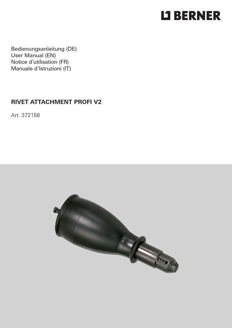
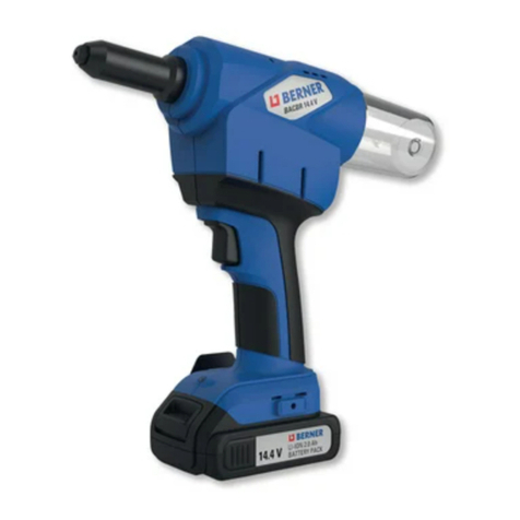
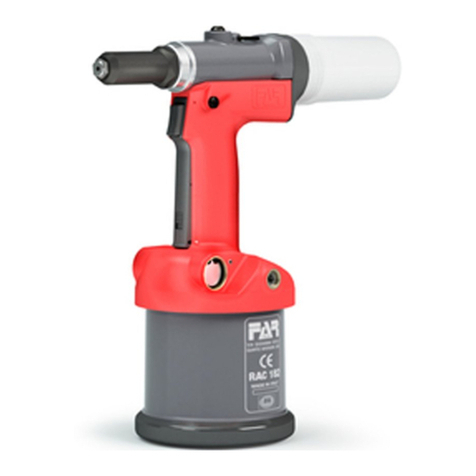
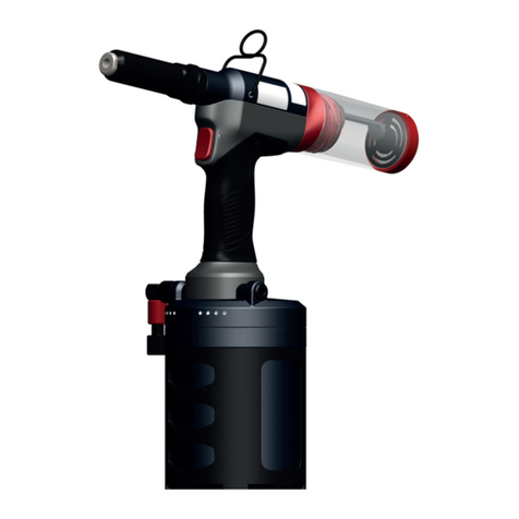
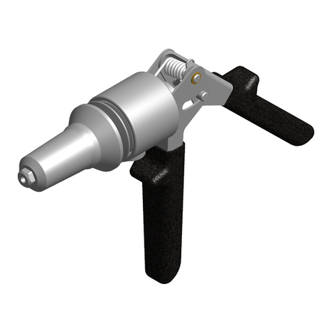
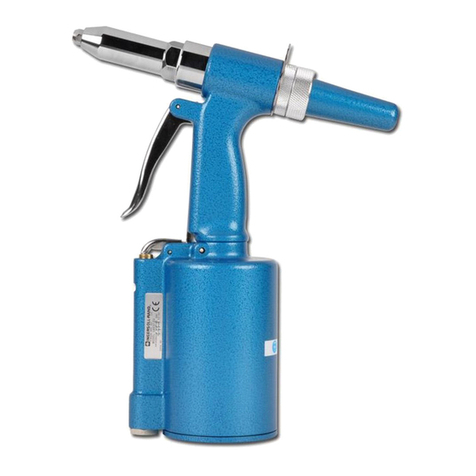
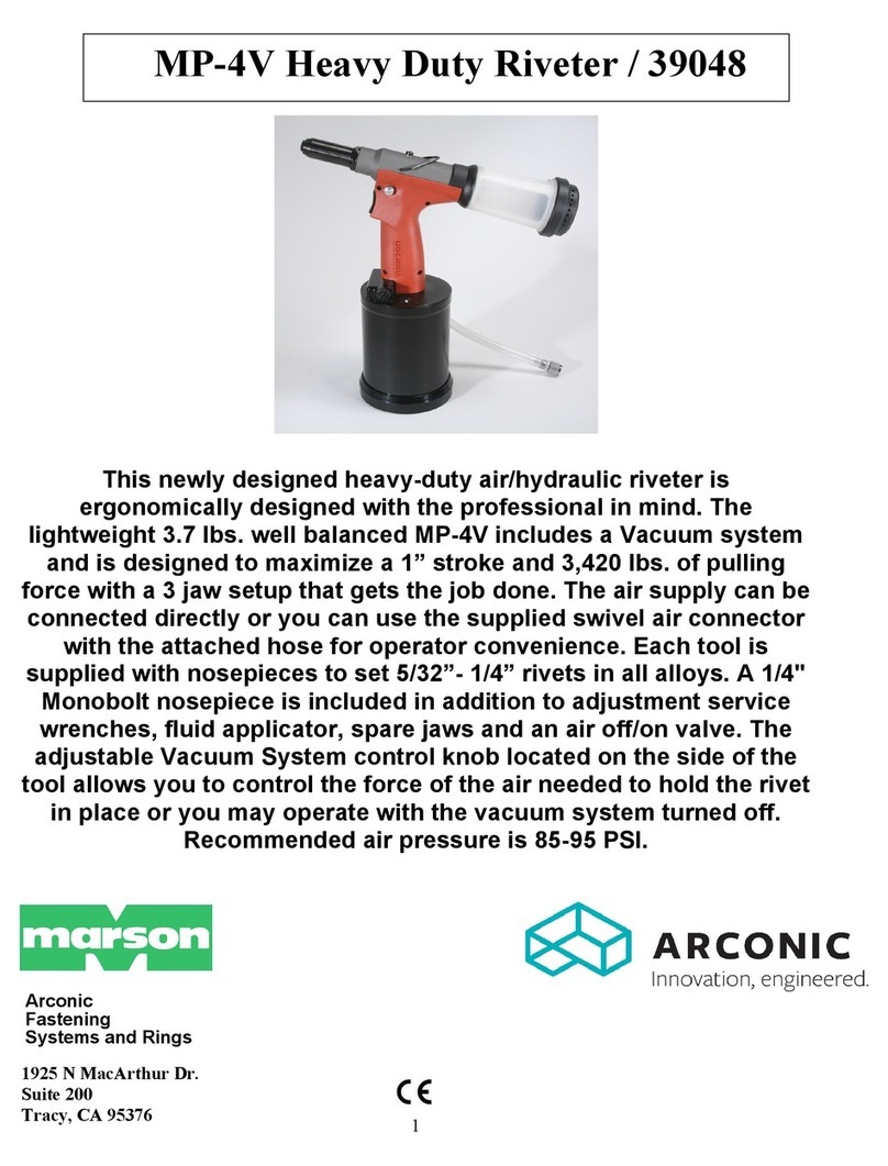
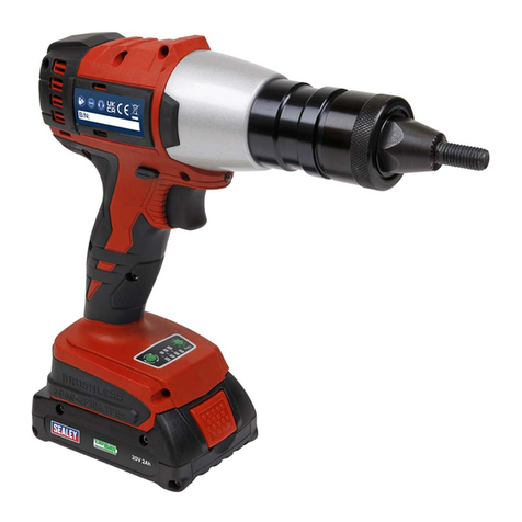
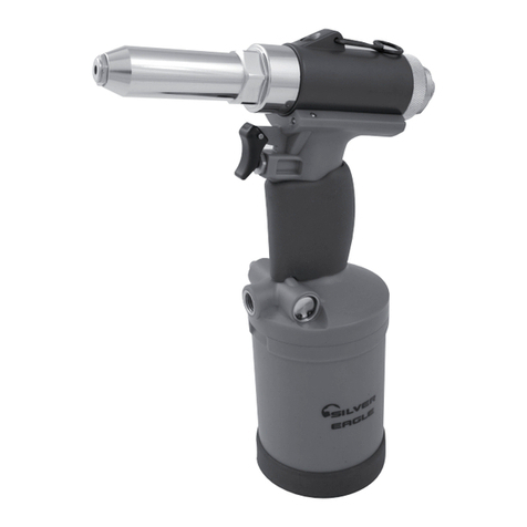
Berner BPT-BR 3.2-5 MM User manual

Bedienungsanleitung (DE)
Instruction Manual (EN)
Notice d’utilisation (FR)
Instrucciones de manejo (ES)
Manual de Instruæoes (PT)
Manuale d’Istruzioni (IT)
Gebruiksaanwijzing (NL)
Brugsanvisning (DK)
Brugsanvisning (SE)
Brugsanvisning (NO)
Instrukcja obsługi (PL)
Návod k použití (CZ)
Manuál (SK)
Használati utasítás (HU)
Instrucţiuni de operare (RO)
Priručnik za upotrebu (HR)
Lietošanas norādījumi (LV)
Naudojimo instrukcija (LT)
BPT-BR 3.2-5 MM RIVET GUN
Art. 414401
BPT-BR 4.8-6.4MM RIVET GUN
Art. 414402

(DE)
· Dieses Werkzeug sollte ausschließlich
zum Anbringen der als Werkzeugkapazität
vorgeschriebenen Blindnieten verwendet
werden. Es kann nicht für andere Zwecke
verwendet werden, z.B.alsHammer usw.
· Das Werkzeug muss bei jeder Art
von Wartung oder Reparatur von der
Druckluftquelle GETRENNT werden.
· VERWENDEN SIE das Werkzeug NICHT,
wenn Sie müde sind oder unter dem Einfluss
von Drogen, Alkohol oder Medikamenten
stehen. Ein Moment der Unaufmerksamkeit
beim Arbeiten mit demWerkzeug kann
zuschweren Verletzungen führen.
· VERWENDEN SIE das Werkzeug
NICHT unter nachfolgend beschriebenen
Umgebungsbedingungen:
Treibsto undVerbrennungsluft.
Schnell steigende Temperatur.
Feuchtigkeit, Regen, Wasser, Sturm
undGewitter.
Das Werkzeug ist nicht für
explosionsgefährdete Bereiche ausgelegt.
· Stellen Sie sicher, dass das Werkzeug
nicht herunterfallen kann, wenn das
Werkzeug während des Gebrauchs am
Bedienungshaken aufgehängt wird.
· Tragen Sie bei der Verwendung des
Werkzeugs stets Sicherheitsschuhe,
Schutzbrillen, Schutzhandschuhe,
Schutzhelm, Gehörschutz und andere
notwendige Schutzausrüstung. Dies wird
aus Sicherheitsgründen dringend empfohlen.
· Entfernen Sie vor dem Einschalten
des Druckluftwerkzeugs die Einstellwerkzeuge
oder Schraubenschlüssel. Ein mit
einem rotierenden Teil des Werkzeugs
verbundener Schraubenschlüssel kann
zuVerletzungen führen.
· Erlauben Sie keinen Personen die Benutzung
des Werkzeugs, die diese Anleitung nicht
gelesen haben oder mit demWerkzeug nicht
vertraut sind.
· Halten Sie beim Arbeiten mit dem Werkzeug
Kinder und andere Personen fern. Wenn Sie
abgelenkt sind, verlieren Sie möglicherweise
die Kontrolle über das Werkzeug.
· Lassen Sie Ihr Werkzeug nur von
qualifiziertem Fachpersonal und nur mit
Originalersatzteilen reparieren. Im Zweifelsfall
das Werkzeug immer an den Händler
zurückgeben.
· Änderungen am Werkzeug, seinem Zubehör
oder an seinen Ersatzteilen liegen in der
alleinigen Verantwortung des Kunden.
· Das Werkzeug muss in einwandfreiem
Zustand gehalten und regelmäßig auf
Beschädigungen und ordnungsgemäßen
Betrieb überprüft werden. Stellen Sie sicher,
dass bewegliche Teile ordnungsgemäß
funktionieren und sich nicht verklemmen
unddass Teile nicht so defekt oder
beschädigtsind, dass die Funktion des
Werkzeugs beeinträchtigt wird. Lassen
Siebeschädigte Teile vor der Verwendung
desWerkzeugs reparieren.
· Zielen Sie mit dem Werkzeug niemals auf
eine andere Person.
· Sauersto oder andere brennbare Gase aus
Druckflaschen dürfen nicht als Antriebsmittel
dienen.
· Vermeiden Sie unnötigen Kontakt mit der
Hydraulikflüssigkeit, um mögliche allergische
Reaktionen der Haut zu vermeiden.
· Entsorgen Sie das Werkzeug nach Ablauf
der Lebensdauer gemäß den geltenden
Entsorgungsvorschriften.
· Der Druckregler muss mit einem Filter
ausgestattet sein, um Verunreinigungen
undNässe zu vermeiden.
LESEN SIE DIESE BEDIENUNGSANLEITUNG SORGFÄLTIG DURCH, BEVOR SIE DAS WERKZEUG BENUTZEN!
Für einen ausreichenden Schutz vor Verletzungen ist es WICHTIG, die Sicherheitshinweise zu befolgen.
Art. 414401
WERKZEUGKAPAZITÄT
Blindnieten 3,0/3,2mm - 4,0mm - 4,8/5,0mm, Standard
WERKZEUG-SPEZIFIKATIONEN
Druck der Luftzufuhr: 0,5Mpa ~ 0,7Mpa
Ausgangszugkraft: 10.300N ~ 14.420N
Hub: 19mm
Nettogewicht: 1,42kg
Art. 414402
WERKZEUGKAPAZITÄT
Strukturelle Monobolzen-Blindnieten oder gleichwertiger Kalottenkopf 4,8mm - MundstückK/3.1
Strukturelle Monobolzen-Blindnieten oder gleichwertiger Kalottenkopf 6,4mm - MundstückM/4.2
Strukturelle Interlok-Blindnieten oder gleichwertiger Kuppelkopf 4,8mm - MundstückJ/3.2
Strukturelle Interlok-Blindnieten oder gleichwertiger Kalottenkopf 6,4mm - MundstückL/4.5
Strukturelle Monobolzen-/Interlok-Blindnieten oder gleichwertiger Senkkopf oder Standardblindnieten 4,8mm - MundstückP/3.3
Strukturelle Monobolzen-/Interlok-Blindnieten oder gleichwertiger Senkkopf oder Standardblindnieten 6,4mm - MundstückL/3.3
WERKZEUG-SPEZIFIKATIONEN
Druck der Luftzufuhr: 0,5Mpa ~ 0,7Mpa
Ausgangszugkraft: 14.225N ~ 19.915N
Hub: 26mm
Nettogewicht: 1,80kg
(DE)
ERSTE SCHRITTE
Bitte beachten Sie die EXPLOSIONSDARSTELLUNG DES WERKZEUGS und die TEILELISTE in dieser Bedienungsanleitung,
umausreichend über die beschriebenen Werkzeugteile informiert zu sein. Die Beschreibungen der Werkzeugteile sind
in dieserBedienungsanleitung kursiv gedruckt, wobei die Positionsnummern der Teile mit der Explosionsdarstellung des
Werkzeugs übereinstimmen.
1) Dieses pneumatisch angetriebene Werkzeug sollte mit Druckluftzufuhr betrieben werden. Es wird empfohlen, einen Luftschlauch
miteinem Durchmesser von über 8mm zu verwenden;
2) Stellen Sie sicher, dass der Druckluftdruck innerhalb des angegebenen Bereichs zwischen 0,5Mpa und 0,7Mpa liegt, und schließen
Sie den Luftschlauchadapter an den Luftadapter des Werkzeugs (Nr.53) an. Für den Luftadapter gibt es in verschiedenen Ländern und
Gebieten unterschiedliche Versionen. Die Werkzeuge sind in der Regel standardmäßig mit der richtigen Version ausgestattet. Sollte der
Luftadapter in Ihrem Adapter für den Luftzufuhrschlauch nicht passend sein, wenden Sie sich bitte an den/die Werkzeughändler;
3) Wechseln Sie je nach Größe des zu setzenden Niets auf das richtige Mundstück (Nr.1) und verwenden Sie dieses.
DiesesWerkzeug ist im Werkzeugset mit den Mundstücken 3,0/3,2mm, 4,0mm und 4,8/5,0mm (am Werkzeug) ausgestattet.
GehenSiewienachstehend beschrieben vor, um das Mundstück (Nr.1) zu wechseln:
a) um den Luftzufuhrschlauch vom Luftadapter (Nr.53) zu entfernen,
b) um mit dem Schraubenschlüssel (im Zubehörpaket) das
Mundstück (Nr.1) vom Werkzeug zu entfernen,
c) um das richtige Mundstück im Zubehörpaket auszuwählen
und auf das Werkzeug aufzuschrauben, wobei es mit dem
Schraubenschlüssel fest auf dem Werkzeug fixiert wird,
d) um den Dornsammler (Nr.25, im Zubehörpaket) auf der
Rückseite des Werkzeugs zu montieren.
WERKZEUGBETRIEB ZUM SETZEN DES BLINDNIETS
1) Setzen Sie nach den Vorbereitungen für die Inbetriebnahme den Niet mit dem Nietdorn in das Mundstück ein und halten
Siedas Werkzeug, um den Niet in das vorgebohrte Loch der Werkstücke einzuführen, in dem die Werkstücke befestigt
werdenmüssen;
2) um den Werkzeugabzug (Nr.49) zu ziehen und den Blindniet in seiner Position auf dem Werkstück zu setzen;
3) Nach dem Setzen des Niets wird der Restdorn der Nieten automatisch in den Dornsammler (Nr.25) gesaugt. Stellen Sie sicher,
dass der Dornsammler (Nr.25) rechtzeitig entleert wird, da das Werkzeug den Dorn sonst nicht richtig freigeben kann.
4) Die Luftleistung beim Ansaugen des Restdorns kann durch den Knopf auf der Rückseite des Werkzeugs, der mit dem
Entfernen des Dornsammlers sichtbar wird, höher oder kleiner eingestellt werden:
5) Am Luftadapterschlauch (Nr.54), mit dem dieses Werkzeug ausgestattet ist, befindet sich ein Schiebeschalter zum
Unterbrechen der Luftzufuhr. Zum Luftsparen ausschalten.
Knopf

(DE)
WERKZEUGPFLEGE
Wenn keine Schmiervorrichtung an der Luftverteilung angeschlossen ist, geben Sie täglich und vor Arbeitsbeginn zur besseren
Leistung des Werkzeugs ein paar Tropfen Hydrauliköl auf den Einlass des Luftadapters (Nr.53) des Werkzeugs, um die Reibung
derWerkzeugteile zu verringern, da das Öl beim Betrieb des Werkzeugs in das Innere des Werkzeugs geblasen wird.
Nach einer gewissen Betriebszeit kann sich der Hub des Werkzeugs verringern, was darauf hinweist, dass das Hydrauliköl des
Druckluftwerkzeugs nachgefüllt oder ausgetauscht werden muss:
1) Die Schraube (Nr.11) mit einem Sechskantschlüssel entfernen. 2) Schließen Sie die Luftzufuhr an und bedecken
Sie das Loch, in dem die Schraube (Nr.11) entfernt
wurde, mit einem Tuch. Ziehen Sie dann den Abzug
(Nr.49). Das Öl tritt aus dem Werkzeug aus.
3) Schrauben Sie den Öleinspritzadapter
(am Öleinspritzset im Zubehörpaket) in das Loch,
indem die Schraube (Nr.11) entfernt wurde.
4) Spritzen Sie das Öl mit dem Öleinspritzer
(imZubehörpaket) langsam ein, bis nicht mehr eingefüllt
werden kann (ca. 15ml), entfernen SiedenÖleinspritzer
und seinen Adapter, befreien SieWerkzeug vom
Ölundbefestigen Sie die Schraube (Nr.11) wieder
festam Werkzeug.
5) Prüfen Sie den Werkzeughub. Wenn der Hub immer noch nicht so ist, wie er sein sollte, bedeutet dies, dass sich
beim Nachfüllen des Öls in das Werkzeug möglicherweise etwas Luft im Ölzylinder (Nr.13) angesammelt hat. Dann
muss die überschüssige Luft aus dem Werkzeug abgelassen werden.
Um das Werkzeug an die Luftzufuhr anzuschließen, ziehen Sie den Werkzeugabzug (Nr.49) 6- oder 7-mal, lösen dann
die Schraube (Nr.11), lassen die überschüssige Luft ausströmen und ziehen dann die Schraube (Nr.11) wieder fest.

(DE)
Nach längerem Gebrauch des Werkzeugs kann es vorkommen, dass die Metallspäne vom Setzen der Nieten im Mundstück des
Werkzeugs verbleiben und die Leistungsfähigkeit des Werkzeugs beeinträchtigen. Daher wird empfohlen, die Teile des Mundstücks
regelmäßig zu reinigen oder auszutauschen.
1) Verwenden Sie den Schraubenschlüssel (im Zubehörpaket) und einen vom Werkzeugbenutzer bereitgelegten Maulschlüssel:
2) So demontieren Sie das Mundstück
(Nr.1) am Werkzeug mit einem
Schraubenschlüssel.
3) So demontieren Sie die vordere
Hülse (Nr.2).
4) So demontieren Sie
die Klemmhülse (Nr.3).
5) Nehmen Sie den 3-Backen-Satz (Nr.4) aus der Klemmhülse (Nr.3) und den
Montageschieber (Nr.5) und die Schieberfeder (Nr.6) aus dem Werkzeug und
dem Dornrohr (Nr.20) heraus und reinigen Sie alles. Überprüfen Sie in der
Zwischenzeit die Teile auf Abnutzung oder Beschädigung, um sie gegen neue
Teile auszutauschen.
6) Montieren Sie die gereinigten oder
neuen Teile wieder an das Werkzeug.
Stecken Sie dieSchieberfeder (Nr.6) auf
den Montageschieber (Nr.5), und setzen
Siediesewieder in das Werkzeug ein,
wo sich derÖlzylinder (Nr.13) befindet.
7) Stellen Sie zum Einsetzen des
3-Backen-Satzes (Nr.4) in die
Klemmhülse (Nr.3) sicher, dass die
3Backen richtig in der Position sitzen.
8) Setzen Sie die Klemmhülse (Nr.3)
mit dem 3-Backen-Satz (Nr.4) in ihrer
Position auf den Montageschieber
(Nr.5), um sicherzustellen, dass sie
festmontiert wird.
9) Montieren Sie die vordere Hülse
(Nr.2) und das Mundstück (Nr.1)
wieder an das Werkzeug.
Dornrohr
Klemmhülse
3-Backen-Satz
Montageschieber
Schieberfeder
Schlüsselweite1 für hinteren Einsteller (Nr.22);
Schlüsselweite2 für Klemmhülse (Nr.3);
Schlüsselweite3 für Mundstücke (Nr.1);
Schlüsselweite4 für vordere Hülse (Nr.2);
im Zubehörpaket
vom Benutzer bereitgelegt

(DE)
STÖRUNGSBESEITIGUNG
GARANTIEBEDINGUNGEN
Während der Garantiezeit darf der Kunde keine anderen als die vom Hersteller zugelassenen Veränderungen (Wartung) vornehmen.
DieReparaturen müssen von einem autorisierten Servicecenter durchgeführt werden.
Um eine Garantiereparatur einräumen zu können, muss der Kunde das defekte Werkzeug mit dem Kaufbeleg an das Servicecenter des
Herstellers zurückgeben. Die Garantie ist nur gültig, wenn sich das Werkzeug in der Garantiezeit befindet (12Monate ab Kaufdatum,
bestätigt durch den Kaufbeleg) und wenn die Nutzungsbedingungen eingehalten wurden.
Die Garantie gilt nicht, wenn verschlissene Ersatzteile ausgetauscht werden müssen (bei normalem Gebrauch des Werkzeugs).
STÖRUNGEN MÖGLICHE URSACHEN LÖSUNGEN
Nietdorn bricht nicht ab
· 3-Backen-Satz verschlissen oder
beschädigt
· Hydrauliköl im Werkzeug nicht
ausreichend
· Luftzufuhr mit niedrigem Druck
· 3-Backen-Satz wechseln
· Hydrauliköl nachfüllen
· Druck der Luftzufuhr innerhalb des
Spezifikationsbereichs erhöhen
Backen rutschen auf Nietdorn
· 3-Backen-Satz verschlissen
· Metallspäne zwischen den Backen
· Schieberfeder ermüdet
· 3-Backen-Satz wechseln
· Backen reinigen
· Schieberfeder austauschen
Nietdorn kann nicht in Mundstück
eingesetzt werden
· Gewählte Mundstückgröße nicht korrekt
· Backen bleiben bei nicht gelöstem
Restdorn hängen
· Auf richtige Größe des Mundstücks wechseln
· Verbliebenen Restdorn durch Demontage
der vorderen Hülse und der Klemmhülse
herausnehmen
Restdorn kann nicht richtig in den
Dornsammler gesaugt werden
· Saugkraft der Dornfreigabe nicht
ausreichend
· Luftzufuhr mit niedrigem Druck
· Saugkraft des Dorns erhöhen, s.
WERKZEUGBETRIEB, Abschnitt4
· Druck der Luftzufuhr innerhalb des
Spezifikationsbereichs erhöhen

(DE)
EXPLOSIONSDARSTELLUNG DES WERKZEUGS (Art. 414401)

(DE)
DP 03.2021 Irrtümer und technische Änderungen vorbehalten
EXPLOSIONSDARSTELLUNG DES WERKZEUGS (Art. 414402)

(EN)
· This tool should be used exclusively to
apply blind rivets prescribed
as TOOL CAPACITY. It can’t be used
for other purposes, such as hammer,
etc.
· The tool must be, during any
kind of maintenance or repair,
DISCONNECTED from the source of
compressed air.
· DO NOT use the tool when you are
tired or under the influence of drugs,
alcohol or medication. One moment of
inattention when working with the tool
can result in serious injuries.
· DO NOT use the tool in the
environment described as below :
fuel and combustion air.
temperature rapidly rising.
humidity, rain, water, storm and
thundering.
The tool is not designed for explosive
environment.
· When the tool is suspended by the
operation hook during use, be sure the
tool will not fall.
· When using the tool, always carry
safety shoes, protective goggles,
protective gloves, safety helmet,
ear protectors and other necessary
protections. It is highly recommended
for safety reason.
· Remove the setting tools or wrenches
before switching on the pneumatic tool.
A wrench connected to a rotating part
of the tool can result in injuries.
· Do not allow persons who have not
read these instructions or who are not
familiar with the tool to use it.
· Keep children and other persons away
when you are working with the tool. If
distracted, you may lose control over
the tool.
· Have your tool repaired only by qualified
specialist personnel and onlywith original
spare parts. If in doubt,always return the
tool to the distributor.
· Any alterations of the tool, its accessories
or spare parts remain in sole responsability
of the customer.
· The tool must be kept in top condition and
regularly tested for damage and proper op-
eration. Check that moving parts function
correctly and do not jam and that parts are
not broken or damaged in such a way that
the function of the tool is impaired. Have
damaged parts repaired before using
the tool.
· Never aim with the tool at another person.
· Oxygen or other flammable gasses from
pressure cylinders must not serve as a
driving agent.
· Avoid unnecessary contact with the
hydraulic fluid to prevent possible allergy
reaction of the skin.
· After the service life, discard the tool ac-
cording to the applicable disposal.
· The pressure regulator has to be equipped
with a filter to avoid impurities and water.
READ THIS MANUAL CAREFULLY BEFORE USING THE TOOL !
It is IMPORTANT to follow the safety instructions for adequate protection against injuries.
Art. 414401
TOOL CAPACITY
blind rivets 3,0/3,2mm – 4,0mm – 4,8/5,0mm standard
TOOL SPECIFICATIONS
Air supply pressure : 0,5Mpa ~ 0,7Mpa
Output traction power: 10,300 N ~ 14,420 N
Stroke: 19 mm
Net weight: 1,42 kgs
Art. 414402
TOOL CAPACITY
Blind structural rivets Monobolts or equivalent dome head 4,8mm - nosepiece K/3.1
Blind structural rivets Monobolts or equivalent dome head 6,4mm – nosepiece M/4.2
Blind structural rivets Interlok or equivalent dome head 4,8 mm – nosepiece J/3.2
Blind structural rivets Interlok or equivalent dome head 6,4mm – nosepiece L/4.5
Blind structural rivets Monobolts / Interlok or equivalent countersunk head or standard blind rivets 4,8mm – nosepiece P/3.3
Blind structural rivets Monobolts / Interlok or equivalent countersunk head or standard blind rivets 6,4mm – nosepiece L/4.3
TOOL SPECIFICATIONS
Air supply pressure: 0,5Mpa ~ 0,7Mpa
Output traction power: 14,225 N ~ 19,915 N
Stroke: 26 mm
Net weight: 1,80 kgs

(EN)
GETTING START TO WORK
Please refer to the TOOL EXPLOSIVE ILLUSTRATION and the PARTS LIST in this manual in order to have a good understanding
of the tool parts described. The descriptions of the tool parts appear in this manual are in italics with the parts position num-
bers corresponding to the tool explosive illustration.
1) This pneumatic powered tool should be worked with compressed air supply. It is recommended to use the air hose with diameter
bigger than 8 mm;
2) To check the compressed air pressure within the specified range between 0,5Mpa and 0,7Mpa, and to connect the air hose adaptor
onto the tool air adaptor (#53). The air adaptor has its dierent versions in dierent countries and areas, normally the tools are equipped
with the correct version as default, in case the air adaptor does not apply in your air supply hose adaptor, contact the tool distributor(s);
3) To change and use correct nosepiece (#1) according to the size of the rivet to be set. This tool is equipped with nosepieces
3,0/3,2mm, 4,0mm and 4,8/5,0mm (on the tool) in the tool kit. Follow the steps below to change the nosepiece (#1):
a) To remove the air supply hose from air adaptor (#53).
b) To use the wrench (in accessories pack) to remove
the nosepiece (#1) from the tool.
c) To select the correct nosepiece in accessories pack
and screw on to the tool, using the wrench to fix it
firmly on the tool.
d) To install the mandrel collector (#25, in accessories
pack) on the back of the tool.
TOOL OPERATION FOR SETTING BLIND RIVET
1) After start-up preparations, to put the rivet into the nosepiece with the rivet mandrel, and holding the tool to insert the rivet
into the pre-drilled hole of the work pieces where the work pieces needs to be fastened;
2) To pull the tool trigger (#49) to set the blind rivet in its position on work piece;
3) After setting the rivet, the rest mandrel of the rivets will be sucked into the mandrel collector (#25) automatically. Be sure to
empty the mandrel collector (#25) in time otherwise the tool can not release the mandrel properly.
4) The air power of sucking the rest mandrel can be adjusted bigger or smaller, by the knob on back of the tool visible when the
mandrel collector removed:
5) On the air adaptor hose (#54) equipped for this tool, there is a sliding switch for pause the air supply. To switch o for saving
air.
Knob

(EN)
TOOL MAINTENANCE
If there is no lubricating device connected in the air distribution, daily and before starting work, for better performance of the tool, add a
few drops of hydraulic oil on the inlet of the air adaptor (#53) of the tool in order to reduce the frictions of the tool parts since the oil will
be blown inside the tool when tool operates.
After certain period of use, the tool stroke might be reduced, it shows the hydraulic oil of the pneumatic tool is necessary to be refilled
or changed:
1) To remove the screw (#11) by hexagon wrench. 2) To connect the air supply and to cover some cloth
over the hole where the screw (#11) removed, then to
pull the trigger (#49) and the oil will be leaked out from
the tool.
3) To screw the oil inject adaptor (on oil injector
set in the accessories pack) into the hole where
screw (#11) removed.
4) To use the oil injector (in the accessories pack) to
inject the oil slowly until not able to refill (approx. 15ml),
to remove the injector and its adaptor, then clean the oil
on the tool and tightly screw on the screw (#11) back to
the tool.
5) To test the tool stroke. If the stroke still not enough as it should be, it means there could be some air in
the oil cylinder (#13) when you refilling the oil to the tool. Then the extra air needs to be released from the
tool.
To connect the tool with air supply, to pull the tool trigger (#49) 6 or 7 times, then loosen the screw
(#11), let the extra air leaking out, then screw on the screw (#11) tight again.

(EN)
After long time use of the tool, it could be possible that the metal chips from rivets setting remains in the nose assembly of the tool
and the tool eciency will be influenced, therefore it is recommended to have the nose assembly parts cleaned or the parts changed
periodically.
1) To use the wrench (in accessories pack) and a spanner prepared by tool user:
2) To disassemble nosepiece (#1) on
the tool by wrench.
5) To take out the 3-jaw set (#4) from the clamping sleeve (#3), and take out
the assembly pusher (#5) and the pusher spring (#6) from the tool, and mand-
rel tube (#20), and clean them all. Meanwhile to check the parts, if any worn
or damaged, to change the new parts.
7) To put 3-jaw set (#4) into the
clamping sleeve (#3), be sure the 3
jaws are seated in it correctly in the
position.
3) To disassemble front sleeve (#2).
8) To put the clamping sleeve (#3) with
3-jaw set (#4) inside it onto the assem-
bly pusher (#5) in their position, to be
sure it is assembled firmly.
4) To disassemble clamping sleeve
(#3).
6) To re-assemble the cleaned parts or new parts
back to the tool. To put the pusher spring (#6)
onto the assembly pusher (#5), and insert it back
to the tool where assembly oil cylinder (#13)
located.
9) To assemble the front sleeve (#2)
and nosepiece (#1) back to the tool.
Wrench hole 1 for assembly rear adjustor (#22);
Wrench hole 2 for clamping sleeve (#3);
Wrench hole 3 for nosepieces (#1);
Wrench hole 4 for front sleeve (#2);
in accessories pack
mandrel tube
clamping sleeve
3-jaw set
assembly pusher
pusher spring
prepared by user

(EN)
TROUBLES SHOOTING
WARRANTY CONDITIONS
During the warranty period, the customer must not perform any alterations other than those permitted by the manufacturer (mainte-
nance). The repairs must be done by an authorized service center.
To admit warranty repair, the customer must return the defective tool to the service center of the manufacturer with the proof of
purchase. Warranty is valid only if the tool is in its warranty period (12 months from the date of purchase confirmed by the proof of
purchase) and if the conditions of use have been respected.
Warranty is not valid if worn spare parts have to be replaced (further to a normal use of the tool).
TROUBLES POSSIBLE CAUSES SOLUTIONS
Rivet mandrel does not break
· 3-jaw set worn o or damaged
· Hydraulic oil in tool not sucient
· Air supply with low pressure
· Change 3-jaw set
· Refill hydraulic oil
· Increase air supply pressure within the
specification range
Jaws slippery on rivet mandrel
· 3-jaw set worn o
· Metal chips between jaws
· Pusher spring fatigued
· Change 3-jaw set
· Clean the jaws
· Change pusher spring
Rivet mandrel can not be put into nosepiece
· Nosepiece size chosen not correct
· Jaws get stuck by rest mandrel not
released
· Change correct size of nosepiece
· Take out the remained rest mandrel by
disassembling front sleeve and clamping
sleeve
Rest mandrel can not be sucked into mand-
rel collector properly
· Mandrel release sucking power not
sucient
· Air supply with low pressure
· Increase the mandrel sucking power, ref.
TOOL OPERATION section 4
· Increase air supply pressure within the
specification range.

(EN)
TOOL EXPLOSIVE ILLUSTRATION (Art. 414401)

(EN)
DP 03.2021 Errors and technical changes reserved
TOOL EXPLOSIVE ILLUSTRATION (Art. 414402)

(FR)
•Cette machine ne doit être utilisée que
pour riveter des rivets qui correspondent
à la CAPACITE DE LA MACHINE. Elle ne
peut pas être utilisée dans un autre but
(marteau etc…).
•DECONNECTER l’alimentation en
air comprimé de la machine avant le
remplacement d’une pièce ou pendant
une réparation.
•NE PAS utiliser la machine en cas de
fatigue, ou sous l’influence de substances
telles que les drogues, l’alcool ou encore
les médicaments.
•NE PAS utiliser la machine dans un
environnement tel que décrit ci-dessous :
- Carburant et air de combustion.
- Hausse rapide de température.
- Humidité, pluie, tempête et orage.
Cette machine n’est pas adaptée aux
environnements explosifs.
•Quand la machine est suspendue par le
crochet d’opération pendant l’utilisation,
s’assurer qu’elle ne puisse pas tomber.
•N’utiliser la machine que sur des supports
pré-percés pour rivet.
•Le port de lunettes protectrices est
obligatoire. Il est recommandé de
porter des chaussures de sécurité, des
vêtements adaptés, des gants, un casque
de sécurité, des protections auditives et
toutes autres protections nécessaires.
•Ne pas porter de vêtements amples ni
de bijoux. Et veiller à garder les cheveux,
vêtements et gants à l’écart des pièces
en mouvement. Les vêtements amples,
les bijoux ou les cheveux longs pourraient
s’emmêler dans les pièces en mouvement.
•Retirer les éventuels accessoires ou clés
de réglage avant de mettre la machine
en marche. Une clé montée sur une
pièce rotative de l’outil peut entraîner des
blessures.
•Ne pas laisser les personnes non
familiarisées ou expérimentées utiliser la
machine.
•Tenir les enfants et toutes autres
personnes à l’écart pendant l’utilisation
de la machine. Un moment d’inattention
peut vous faire perdre le contrôle de la
machine.
•Toute modification de l’outil, de ses
accessoires ou de ses pièces de rechange
reste sous la seule responsabilité du
client.
•N’utiliser que les pièces de rechange
vendues par le fabricant.
•Les réparations doivent être eectuées par
une personne habilitée. En cas de doute,
toujours retourner l’outil au distributeur.
•L’outil doit être entretenu correctement
et il doit être régulièrement testé pour
vérifier son bon fonctionnement. Vérifier
que les pièces mobiles ne bloquent pas
le système. Vérifier également qu’aucune
pièce ne soit cassée ou endommagées,
cela pourrait altérer le fonctionnement de
l’outil. Toujours faire réparer les pièces
endommagées avant d’utiliser l’outil.
•Ne jamais diriger la machine vers soi, vers
une autre personne ou vers un animal.
•L’oxygène ou d’autres gaz inflammables
provenant de bouteilles à pression ne
doivent pas servir d’agent d’entraînement.
•Éviter tout contact inutile avec le fluide
hydraulique afin d’éviter toute réaction
allergique de la peau.
•A la fin de sa durée de vie, jeter l’outil
dans un endroit adapté afin que les pièces
puissent être recyclées.
•Le régulateur de pression doit être équipé
d’un filtre pour éviter les impuretés et
l’eau.
CE MANUEL D’UTILISATION DOIT ÊTRE LU ATTENTIVEMENT AVANT TOUTE UTILISATION DE LA MACHINE !
Il est IMPORTANT de suivre les instructions de sécurité pour une bonne utilisation de la machine sans
prise de risque
Art. 414401
CAPACITE DE LA MACHINE
Rivets aveugles standard 3,0/3,2mm – 4,0mm – 4,8/5,0mm
CARACTERISTIQUES DE LA MACHINE
Pression circuit d’air comprimé : 0,5bar ~ 0,7bar
Force : 10,300 N ~ 14,420 N
Course : 19 mm
Poids net : 1,42 kgs
Art. 414402
CAPACITE DE LA MACHINE
Rivets de structure type Monobolts ou équivalent, tête plate, diamètre 4,8mm - nez K/3.1 art. code P09011-00
Rivets de structure type Monobolts ou équivalent, tête plate, diamètre 6,4mm – nez M/4.2 art. code P09013-00
Rivets de structure type Interlok ou équivalent, tête plate, diamètre 4,8mm – nez J/3.2 art. code P09010-00
Rivets de structure type Interlok ou équivalent, tête plate, diamètre 6,4mm – nez L/4.5 art. code P09012-00
Rivets de structure type Monobolts / Interlok ou équivalent, tête fraisée ou rivets standards diamètre 4,8mm – nez P/3.3 art. code
P03147-00
Rivets de structure type Monobolts / Interlok ou équivalent, tête fraisée ou rivets standards diamètre 6,4mm – nez L/4.3 art. code
P03146-00
CARACTERISTIQUES DE LA MACHINE
Pression circuit d’air comprimé :
0,5bar ~ 0,7bar
Force : 14,225 N ~ 19,915 N
Course :26 mm
Poids net :1,80 kgs

(FR)
AVANT TOUTE UTILISATION
Afin de bien comprendre les pièces de l’outil décrites dans ce mode d’emploi,
veuillez-vous reporter au schéma d’illustration de l’outil et à la liste des pièces.
1) Cet outil à moteur pneumatique doit être utilisé avec une alimentation en air comprimé.
Il est recommandé d’utiliser un tuyau d’air dont le diamètre est supérieur à 8 mm.
2) Vérifiez que la pression de l’air comprimé se situe entre 0,5 et 0,7 MPa, et connectez l’adaptateur du
tuyau d’air sur l’adaptateur de l’outil. L’adaptateur d’air de l’outil existe en diérentes versions selon les pays
et les régions. Normalement, les outils sont équipés par défaut de la bonne version. Si l’adaptateur d’air de
l’outil ne correspond pas à votre adaptateur du tuyau d’alimentation en air, veuillez contacter le distributeur
de l’outil.
3) Changez et sélectionnez le bon nez en fonction de la taille du rivet à poser. Cet outil est fourni avec
des nez de pose pour des rivets de diamètres 3,0/3,2mm, 4,0mm et 4,8/5,0mm. Suivez les étapes
ci-dessous pour changer le nez de pose.
a) Retirez le tuyau d’air de l’adaptateur.
b) Utilisez la clé fournie pour retirer le nez de pose de l’outil.
c) Sélectionnez le bon nez et vissez-le sur l’outil
en utilisant la clé pour le fixer correctement.
d) Installez le bol récupérateur à l’arrière de l’outil.
REGLAGE DE L’OUTIL POUR LA POSE DE RIVETS
1) Après avoir suivi les étapes de préparation préalables, insérer la tige du rivet dans le nez de pose puis tout en
maintenant l’outil, positionner la tête du rivet dans le trou préalablement percé du support de pose.
2) Appuyer sur la gâchette pour fixer le rivet.
3) Après la pose, la tige tombe automatiquement dans le bol récupérateur. Assurez-vous de vider le bol
récupérateur régulièrement pour un bon fonctionnement de l’outil.
4) Vous pouvez régler la puissance à l’aide du bouton situé à l’arrière de l’outil.
5) Vous pouvez également suspendre l’alimentation en air en faisant
coulisser la bague d’ouverture/fermeture du circuit d’alimentation.
Knob

(FR)
ENTRETIEN DE L’OUTIL
Si la machine n’est pas équipée d’un dispositif de lubrification au niveau de la distribution d’air, il est recommandé
d’ajouter régulièrement quelques gouttes d’huile hydraulique à l’entrée de l’adaptateur d’air afin de préserver
performances de l’outil. Quand l’outil est en marche, l’huile est injectée à l’intérieur du système et permet de
réduire les frictions entre les diérentes pièces.
Après une certaine période d’utilisation, la course de l’outil peut être réduite. Cela indique que vous devez remettre
de l’huile hydraulique dans l’outil pneumatique ou changer d’huile :
1) Retirez la vis à l’aide d’une clé hexagonale :
2) Connectez l’arrivée d’air et recouvrez le trou où
la vis a été retirée avec un chion puis relâcher
la gâchette pour que l’huile s’échappe de l’outil :
3) Vissez l’adaptateur d’injection d’huile (fourni avec
les accessoires) dans le trou où la vis a été retirée :
4) Utilisez l’injecteur d’huile (fourni avec
les accessoires) pour injecter l’huile lentement
jusqu’à ce que vous ne puissiez plus remplir.
Retirez l’injecteur et son adaptateur, puis nettoyez
l’huile sur l’outil et vissez correctement la vis à l’outil.
5) Testez la course de l’outil. Si la course ne sut toujours pas, cela signifie qu’il y a peut-être de l’air qui
s’est installé dans le cylindre d’huile lorsque vous le remplissiez. Il faut donc libérer l’air de l’outil.
Connectez l’outil à l’alimentation d’air, appuyez sur la gâchette de l’outil 6 ou 7 fois, puis desserrez la vis,
laissez s’échapper l’air supplémentaire, puis revissez à nouveau la vis :

(FR)
Après plusieurs utilisations, il est possible que de petits bouts de métal soient coincés dans l’assemblage
du nez ce qui altère la performance de l’outil. C’est pourquoi il est recommandé de nettoyer ou de changer
régulièrement les pièces de l’assemblage.
1) Vous pouvez utiliser la clé fournie avec l’outil ou une clé de votre choix :
2) Démontez le nez de pose de l’outil : 3) Démontez la partie avant : 4) Démontez la douille de serrage :
5) Retirez toutes les pièces de l’assemblage, le jeu de 3 mors, la tige
d’assemble, le ressort, pour les nettoyer.
Pensez également à vérifier si certaines pièces sont abimées afin de pouvoir
les changer :
6) Pour assembler de nouveau les parties
nettoyées, mettez le ressort sur la tige d’assem-
blage, et insérer cet ensemble dans l’outil au
niveau de la partie cylindrique huilée :
7) Mettez le jeu de 3 mors dans
la douille de serrage et assurez-vous
qu’ils soient bien positionnés comme
sur le schéma ci-dessous :
8) Mettez la douille de serrage avec le
jeu de 3 mors correctement positionnés
sur la tige d’assemblage et assurez-vous
que tout soit bien fixé.
9) Assemblez la partie avant et le nez
de pose sur l’outil :
Tube de mandrin
Manchon de serrage
Jeu de 3 mors
Curseur de montage
Ressort de glissière
Partie n°1 de la clé : pour l’ajusteur arrière ;
Partie n°2 de la clé : pour la douille de serrage ;
Partie n°3 de la clé : pour les nez de pose ;
Partie n°4 de la clé : pour la partie avant ;
dans le paquet d‘accessoires
fourni par l‘utilisateur

(FR)
EVENTUELS PROBLEMES RENCONTRES
CONDITIONS DE GARANTIE
Pendant la période de garantie, le client ne doit eectuer aucune modification autre que celles autorisées par le
fabricant (maintenance). Les réparations doivent être eectuées par un centre de service habilité.
Pour bénéficier d’une réparation sous garantie, le client doit renvoyer l’outil défectueux au centre de service du
fabricant avec la preuve d’achat. La garantie n’est valable que si l’outil est dans sa période de garantie (12 mois à
compter de la date d’achat confirmée par la preuve d’achat) et si les conditions d’utilisation ont été respectées.
La garantie n’est pas valable si les pièces de rechange usées doivent être remplacées (suite à une utilisation
normale de l’outil).
PROBLÈMES CAUSES POSSIBLES SOLUTIONS
La tige du rivet ne se case pas.
· Le jeu de 3 mors sont usés ou abimés
· Le niveau d’huile n’est pas susant
· La pression de l’air est trop basse
· Changer les jeux de mors
· Remplir le réservoir d’huile
· Augmenter la pression de l’air
Les jeux de mors glissent sur le mandrin
· Le jeu de 3 mors sont usés ou abimés
· Des bouts de métal sont coincés entre les
mors
· Le ressort est usé
· Changer les jeux de mors
· Nettoyer les mors
· Changer le ressort
Impossibilité de mettre la tige
du rivet dans le nez de pose
· La taille du nez de pose choisi n’est pas la
bonne
· Les mâchoires sont bloquées par une tige
non libérée
· Sélectionner la bonne taille de nez
· Retirez manuellement la tige du rivet en
démontant la partie avant et la douille de
serrage
La tige du rivet n’est pas aspirée
correctement dans le bol récupérateur
· La puissance d’aspiration n’est pas
susante ;
· La pression de l’air est trop basse.
· Augmentez la puissance d’aspiration
· Augmenter la pression de l’air
This manual suits for next models
3
Table of contents
Languages:
Other Berner Rivet Tools manuals
Popular Rivet Tools manuals by other brands

Cherry Aerospace
Cherry Aerospace G-689 Original instructions

BGS technic
BGS technic BGS 3284 instruction manual

HS-Technik
HS-Technik NutBee NBPS-21 operating instructions

Emhart Teknologies
Emhart Teknologies RP4 Operator's manual

Bollhoff
Bollhoff RIVQUICK B2000 manual

BGS technic
BGS technic 404 instruction manual

Metabo
Metabo NP 18 LTX BL 5.0 Original operating instructions

CEVIK PRO
CEVIK PRO NE-KN6615K instruction manual

FAR
FAR RAC 210 TRANSLATION OF ORIGINAL INSTRUCTIONS

Sealey
Sealey AK3986.V2 quick start guide

Milwaukee
Milwaukee M12BPRT-0 Original instructions

Parkside
Parkside 383216 2110 Operation and safety notes