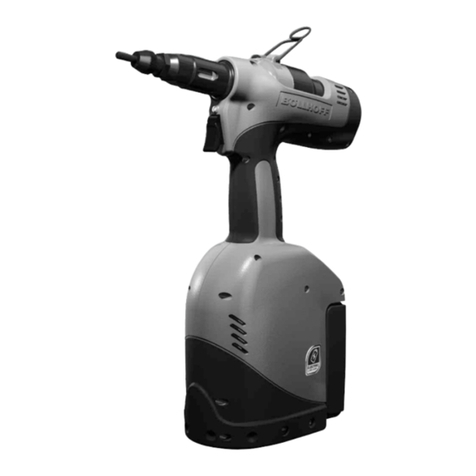
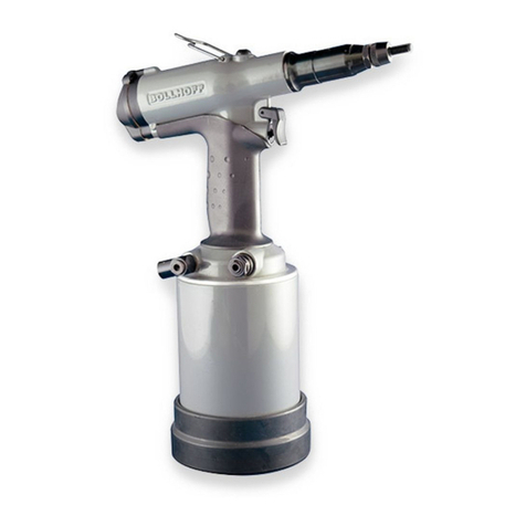
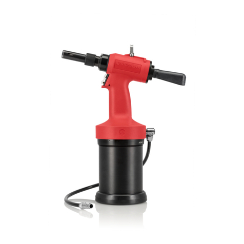
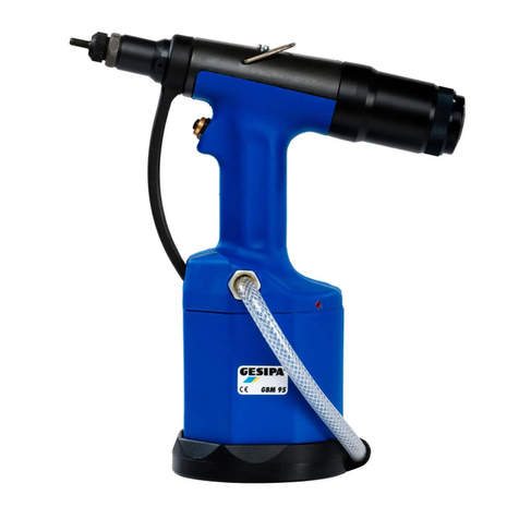
Bollhoff P803 User manual

P803 / 00.11.14
OPERATING INSTRUCTIONS
SETTING TOOL FOR RIVKLE®
BLIND RIVET NUTS AND STUDS
AIM INDUSTRIES
6216 Transit Road
Depew, NY 14043
Tel. 716-681-6196
Fax. 716-681-1610
www.AIMFasteners.com

P803 / 00.11.14
2
CONTENTS
I TOOL DESCRIPTION.............................................................................................................................................................p 2
II ACCESSORIES ......................................................................................................................................................................p 4
III TOOL USE ............................................................................................................................................................................p 6
IV MAINTENANCE.................................................................................................................................................................p12
V TROUBLESHOTTING AND SOLUTIONS........................................................................................................................ p 13
TOOL DESCRIPTION
Purpose and use of this type of tool
The P803 tool is used to crimp RIVKLE®blind rivet nuts and studs in material which has been pre-drilled or
pierced.
To crimp the RIVKLE® blind rivet nut or stud
The tool provides a setting force using air pressure. This principle has some advantages:
- Ability to crimp the same RIVKLE® on various thickness without any adjustment of the tool.
- improved mandrel and overall tool life due to the ability to supply the optimal force needed for setting.
- Possibility of a second crimping without any risk of stripping the thread.
Specifications
- Setting capacity: RIVKLE®from M3 to M8 (#6-5/16 unified)
- Max. stroke : 7 mm (0.28 in)
- Working pressure: 5,5 bars min to 7 max.
- Weight, when set up for M6: 2.1 kg
- Air consumption: 8L maximum
- Noise level : < 70 dB (A)

P803 / 00.11.14
3
M3 M4 M5 M6 M8
Fig. 1 A 78 78 78 78 78
Table 1 (P4) L 32 31 41 42 42
Fig. 2 A 59 59 59 59 59
Table 2 (P5) L 33 34 40 42 47
SAFETY : BEFORE WORKING ON THE P803 TOOL,
PLEASE DISCONNECT THE COMPRESSED AIR

P803 / 00.11.14
4
ACCESSORIES
Configuration when using cap screws as mandrels (Figure 1 & Table 1)
fig. 1
Kit Including
Items 1,2,3,4, &
138
Item 1
(Bolt) Item 2
(Anvil) Item 3
(Spacer) Item 4
(Hex Driver)
M3 2368 0303 000 CHC ISO4762
DIN912 : M3 x 60 2361 1303 030 2368 0303 040 2368 0303 010
M4 2368 0304 000 CHC ISO4762
DIN912 : M4 x 60 2361 1304 030 2368 0304 040 2368 0304 010
M5 2368 0305 000 CHC ISO4762
DIN912 M5 x 70 2361 1305 030 2368 0305 040 2368 0305 010
M6 2368 0306 000 CHC ISO4762
DIN912 : M6 x 70 2361 1306 030 2368 0306 040 2368 0306 010
M8 2368 0308 000 CHC ISO4762
DIN912M8 x 70 2361 1308 030 None required 2368 0308 010
ITEM 138 is PN 2368 0300 138 Table 1
How to change the mandrel
•Loosen the anvil lock-nut and unscrew the anvil (2)
•Unscrew the nose (5)
•Put the screw through the ring(3), which corresponds to the diameter (no ring for M8)
•Put the driver (4) in the recess of the mandrel (1)
•Let the assembly slide into the traction socket (7)
•Replace the nose (5)
•Replace the anvil and the lock-nut (2)

P803 / 00.11.14
5
Configuration when using P330/P320 style mandrel (Fig. 2 Table 2)
If you have already bought a P330/P320 tool you can use the mandrel. You only need to buy a nosepiece
part number 2368 0300 400.
fig. 2
For Rivet Nuts For Blind Studs
Item 1 Item 2 Item 1 Item 2
M3 2361 1303 020 2361 1303 030 3761 1303 020 3761 1303 030
M4 2361 1304 020 2361 1304 030 3761 1304 020 3761 1304 030
M5 2361 1305 020 2361 1305 030 3761 1305 020 3761 1305 030
M6 2361 1306 020 2361 1306 030 3761 1306 020 3761 1306 030
M8 2361 1308 020 2361 1308 030 3761 1308 020 3761 1308 030
#6-32 2361-1367-620 2361-1335-030
#8-32 2361-1368-620 2361-1368-030
#10-24 2361-1369-620 2361-1369-030
#10-32 2361-1369-720 2361-1369-030
1/4-20 2361-1374-620 2361-1374-030
1/4-28 2361-1374-720 2361-1374-030
5/16-18 2361-1376-620 2361-1308-030
5/16-24 2361-1376-720 2361-1308-030
table 2
To change to the mandrel and anvil :
•Hold the nosepiece (5), loosen the anvil locknut and remove the anvil (2) and its locknut.
•Remove the pin (9) with a special tool without damaging the ring (8) and remove the old mandrel (1)
•Place the new mandrel (1) and reinsert the pin (9), making sure that the ring (8) remains in the groove.
•Screw the nosepiece(5) on tightening to 15 Nm.
•Screw the new anvil (2) into the nosepiece, leaving the locknut loose.

P803 / 00.11.14
6
TOOL USE
Adjustment of the anvil (fig 3)
•The anvil position depends on the length of the RIVKLE®before crimping.
•Adjust the anvil position as indicated in figure 3
•After the adjustment, tighten the anvil lock-nut (2) at 10 Nm.
1 mm
Fig. 3

P803 / 00.11.14
7
Fig. 4
Item 1
Filter
Item 2
Air Regulator
Item 4
Air hose 3m
Item 1&2 is PN 2368 0300 403
Item 4 is PN 2368 0300 402
Air System (fig 4)
The power supply of the tool is compressed air. The optimum pressure is 6 bars. We suggest the use of an air
filtration unit, which includes oiling, filtering processes and pressure regulation in the air power unit. This unit
should be placed up to 3 meters from the tool (see the schematic on pg. 7) in order to obtain an optimum life cycle
for the tool and to reduce the amount of maintenance to a minimum.
ALL THE AIR HOSES MUST HAVE AT LEAST A 6.4 mm OR A ¼ INCH INTERNAL DIAMETER.

P803 / 00.11.14
8
Suspension system (fig 5)
You can use the tool either suspended or unsuspended.
Fig. 5
INSTRUCTIONS FOR TOOL USE
•Connect the air pressure power to the tool.
•To position the RIVKLE®on the mandrel, press the RIVKLE®on the mandrel end and the mandrel will
autospin into the RIVKLE®.
•Introduce the RIVKLE®into the workpiece.
•Press the trigger. This crimps the RIVKLE®in the workpiece and auto unscrews the mandrel.
Adjustment of the crimping pressure
•Check that the system pressure is set between 5 and 7 bars (75 - 105 PSI).
•Before activating the crimping process, set the pressure to 0 by turning the setting adjustment to minimum.
•Progressively increase the crimping pressure by turning the adjustment towards (+)
•Step by step, test the crimping quality of the RIVKLE®up to the optimal crimping.
•The optimal crimping (s) is indicated in the Bollhoff RIVKLE® brochure.(fig.6)
CAUTION :
Setting the pressure too high can damage the thread of the RIVKLE®the thread of the mandrel or prevent
the mandrel from being unscrewed.
When you find the correct setting, please note the position of the setting adjustment.
Adjustment of the unscrewing time

P803 / 00.11.14
9
The unscrewing process is predetermined when delivered. This timing can be optimized when using specific
RIVKLE®. In order to improve the process, you must set the screw on the back of the tool ( E206 ).
If the screw is turned clockwise, the time is longer, turning counterclockwise shortens the unscrewing time.
Unscrewing button
In case of unscrewing problems, the P803 tool is equipped with a reverse button at the back. To reverse the tool,
you need to press the button ( 34 ).
Fig. 6

P803 / 00.11.14
10

P803 / 00.11.14
11
Part # Qty Description Part # Description
001 1 Mandrel 040 1 Spring ring
002 1 Anvil 041 1 Nylon ball 7/32
003 1 Bushing 042 1 Tank bushing
004 1 Insert 043* 1 O Ring
005 1 Nose piece 044* 1 O Ring
006 1 Coupling 045* 1 Back-up ring
007 1 Mandrel coupling 046* 1 Guide
008* 1 Spring ring 047* 1 Air inlet rose
009 1 Mandrel drive pin 048 1 Back-up ring
011 1 Dowel 058 1 Spring ring
013 1 Locking nut 060 1 Piston rod
014 1 Hook 061* 1 Seal
015* 1 Guide 062* 1 Seal
016* 1 Back-up ring 063 1 Circlip
017* 1 O Ring 064 1 Base
018 1 Bolt M8x10 065 1 Piston head
019 1 Washer 066 1 Piston
020* 2 Spacer 067 1 M8 bolt
022* 1 O Ring 071 1 Plastic Sleeve
023* 1 Back-up ring 078 1 Ball pin
024* 1 Guide 118 3 Seal
025 1 Receiver piston 129 1 Shutter
026 1 Spring ring E201 1 Air motor
027 1 Body E202* 1 Push-pull valve
028 1 Distributor E203* 1 Trigger valve
029 1 alignment pin E204 1 Trigger
030 1 Locking ring E205* 1 Pressure regulator
valve
031 1 Spring ring E206* 1 Needle valve
032 1 Rear plug E207 1 Air union
033* 1 Silencer E208 1 Air cylinder
034 1 Reverse button E209 1 Drive shaft
035* 2 O Ring E210 1 Push-pull valve
sleeve
039 1 Dowel E211 1 Push-pull rod
(not shown)
Codification of the spare parts for your orders:
2368 0300 XXX substitute XXX for one of the part numbers shown above
Ex1: Rep 9 : Mandrel drive pin : 2368 0300 009 Ex2 : Rep E201 : Motor : 2368 0300 201

P803 / 00.11.14
12
MAINTENANCE
Daily Maintenance
•Check that the mandrel is suitable for the RIVKLE®.
•Check that the crimping pressure of the tool is suitable for the setting of the designated RIVKLE®(see pressure
adjustments).
•If the mandrel is damaged or if you have difficulty unscrewing the nut, you must change the mandrel
•Check that the following processes "screwing- crimping- unscrewing" are activated by pressure on the spindle
and trigger, without any RIVKLE®in place.
•Check the anvil adjustment. Verify that the RIVKLE®is firmly and squarely against the anvil.
•Always hold the mandrel perpendicular to the work.
•About every 300 RIVKLE®, the mandrel must be lubricated .
•After use, protect the mandrel with a RIVKLE®
General Maintenance
IMPORTANT
The maintenance of the tools must be carried out by skilled technicians. The operator should not be involved
in maintenance or repair of the tool unless the operator is skilled in these types of operations.__
The air pressure supply must be switched off before every repair or maintenance operation.
After 500,000 cycles, the tool should be disassembled, and worn and damaged parts replaced.
The following repair kits are available for the P803 tool.
*Push-pull valve kit 2368 0300 202
*Trigger valve kit 2368 0300 203
*Regulator valve kit 2368 0300 205
*Unscrew check valve kit 2368 0300 206
*Complete repair kit (includes all of the above) 2368 0300 200
The repairs must be performed in a clean area. Special service tools may be required (available from your Bollhoff
supplier)
Adding Oil
•Recommended oil type: Mobil DTE (ISO VG 68) Hydrolub H68 Condat or similar.
•Switch off the compressed air pressure.
•Take out the upper screw from the oil reservoir (18)
•Check the oil level in the hole (18), and top-up the oil until full to the bottom of the thread.
•Replace the screw (18) with the seal (19)
•Reconnect the compressed air and check the crimping pressure after maintenance.
•In case of an insufficient stroke, repeat the operation.

P803 / 00.11.14
13
TROUBLESHOOTING AND SOLUTIONS
TROUBLE HYPOTHETICAL REASON SOLUTIONS
Thread of the mandrel damaged
Difficulties in screwing and
unscrewing
1 - Incorrect grip range of the
RIVKLE
2 - Too long a crimping stroke
3 - Holding of the tool incorrect
when crimping
1 - Check the crimping value in the
RIVKLEbrochure.
2 - Try again to crimp the
RIVKLE. Following the
instructions
3 - Hold the traction mandrel
perpendicular to the
component
RIVKLEthread damaged after
setting thread. 1 - Damaged mandrel thread.
2 - RIVKLEnot completely
screwed on mandrel.
3 – crimping force too high
4 - Thickness of the crimped
component unsuitable with
the RIVKLE
1 -Replace the mandrel according
to the instructions
2 - Adjust the anvil position
according to the instructions
3 - Try again to crimp the
RIVKLE. Following the
instructions
4 - Check the crimping value in the
RIVKLEcatalogue
RIVKLEis not set in the
material 1 - Incorrect grip range for the
RIVKLE
2 - The RIVKLEhead is not in
contact with the anvil when
crimping
3 - Crimping pressure insufficient
1 - Check the crimping value in the
RIVKLEbrochure.
2 – Make sure the RIVKLEhead
is in contact with the anvil
when setting
3 - Try again to crimp following
the instructions
Tool pressure insufficient 1 - Compressed air pressure
insufficient
2 - Lack of oil
1 - Check the pressure supply
2 - Add oil according to the
instructions. (page 12)
Mandrel does not unscrew after
installation of the Rivkle 1 - Damaged mandrel thread or
RIVKLE
2 - Time for unscrewing too long
3 - Compressed air pressure
insufficient
1 - Replace as required
2 - Turn the screw (E206)
3 - Check the pressure supply
Unscrewing process occurs each
time without crimping 1 - Problem in the crimping
pressure adjustment 1 - Reduce the air pressure of the
crimping and try again on a
RIVKLE
2 - in case of continuous problem,
contact your Bollhoff supplier
Other Bollhoff Rivet Tools manuals
