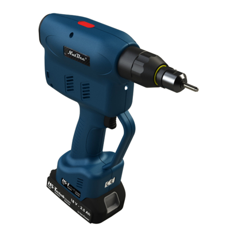
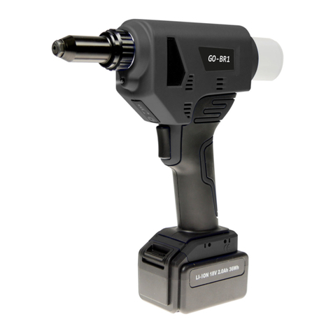
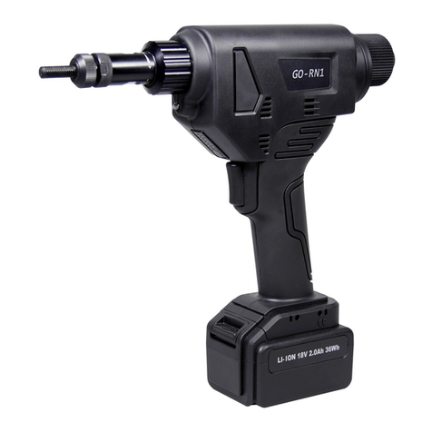
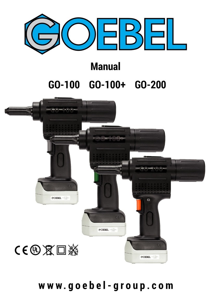
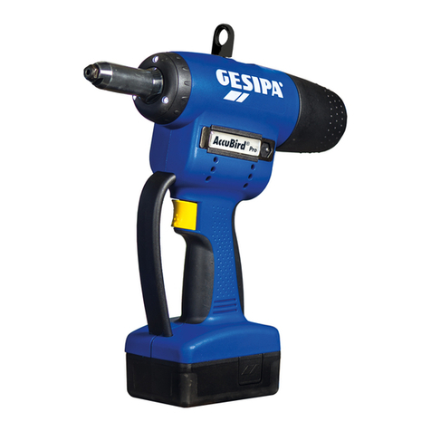
GOEBEL GO-BR1 User manual

User Manual
innovative fastener solutions
GO - BR1
GO - BR2
GO - TR1
Cordless Blind Rivet Battery Tool

2| Deutsch1| English
User Manual: GO-BR1 / GO-BR2 / GO-TR1
Table of contents
www.goebel-group.com
Page
Safety precautions 2 - 4
Daily maintenance & environmental protection 4
1. Machine overview
1.1 Capacity
1.1 Technical parameters
1.2 Conguration/ Accessories (see g. A)
1.3 Parts List (see g. B)
1.4 GO-BR series tool parts list
4
5
5
5 - 6
7
8
2. Preparation of the tool
2.1 Changing the mouthpiece
2.2 Changing the jaws
2.3 Other spare parts
2.4 Battery check
2.5 Checking the tool
9
9
9
10
10
10
3. Function settings
3.1 Setting the stroke
3.2 Setting the riveting mode
11
11
11
4. Tool operation
4.1 Riveting in conventional mode (D)
4.2 Rivets in self-locking mode (S)
12
12
12
5. Charger & Batteries
5.1 Technical parameters
5.2 Charger usage
5.3 Battery usage
13
13
13
13
6. FAQ (Questions / Answers) 14
7. Troubleshooting
7.1 Failfunction
7.2 Probable cause
7.3 Correction of defects
14
14
14
14
8. Protection conditions & CE certication 15

Deutsch | 2English | 2
To reduce the risk of electric shock, personal injury, re and property damage, be sure
to observe the following safety precautions.
Description of the symbols:
www.goebel-group.com
Safety precautions
Danger
Indicates imminent hazards which, if not avoided will result in serious injury or death
Warning
Indicates potential hazards which, if not avoided could result in serious injury or death
Caution
Indicates potential hazards which, if not avoided may result in minor injury or loss of property
The following characters are used to classify and describe the types of description to
be followed.
This sign is used to alert the user to the prohibited action steps.
This sign is used to draw users' attention to the operating steps that must be
carried out to use the appliance.
• This tool is limited to riveting holes and must not be used for percussion or other
purposes, such as a hammer.
• Please do not carry out riveting without sheet material! Make sure to mount and
tighten the remaining rivet mandrel catcher to prevent remaining rivet mandrels from
ying out and causing injuries!
• Do not overload the riveting tool. Please use it within the range specied in the Set-
tings function (see P10).
• Do not block the venting of the motor. Do not insert any objects into the vent.
• It is recommended to wear safety glasses and personal protective equipment when
using this tool e.g. gloves, hard hat, safety shoes, noise-insulating earplugs and fall
protection devices and other necessary protective measures.
Please keep the packaging boxes and accessories and handle them with care.
• The tool and accessories should be placed in the plastic case, stored in a dry place
and out of the reach of children.
Caution

2| Deutsch3| English
Safety precautions
www.goebel-group.com
Use of the battery
• Do not charge damaged, contaminated or wet batteries.
• Batteries must not be thrown into water or re at any time, and used batteries must
not be disposed of at will.
• Do not charge when the ambient temperature is below 0°C or above 45°C.
Use of the charger
• The original battery and the manufacturer's charger must be used for charging.
• The battery must not be charged with a damaged, dirty or damp charger.
• Do not place metal objects in the charging area as a short circuit may occur.
• This charger must not be used by persons with disabilities, mental disabilities or
persons without training or knowledge unless a safety ofcer is on site to supervise
or instruct them in the use of the charge.
Danger
• Do not use the riveting tool in a damp environment or near ammable liquids and
gases. Risk of explosion!
• Do not point the riveting tool at yourself, others or animals.
• Do not load in a damp environment, near an open re or in an environment with
ammable, highly combustible gases that can easily be detonated.
Warning
• Tools should be placed so that they do not fall down to avoid unnecessary damage
and safety accidents.
• When installing the battery, make sure to x its position. An audible "click" sound will
indicate that the battery is in place.
• When servicing this riveting tool, the battery must be removed.
• Before charging, check that the charger and its power supply equipment are in good
condition.
• Use a power supply unit that matches the charger.
• Plugs, power cords and chargers should be checked regularly. If a problem is found, it
should be repaired by qualied maintenance personnel.
• Maintenance personnel must have professional skills; only qualied professionals
can carry out repairs. If in doubt, please return the unit to the authorised dealer or
manufacturer for repair.
• Original spare parts must be used during maintenance.

Deutsch | 2English | 4
www.goebel-group.com
Maintenance
• Regular maintenance prolongs the life of tools with a lithium battery and should be
carried out by an authorised dealer or manufacturer. In case of more frequent use, it
is recommended to carry out maintenance in advance.
• Maintenance of the riveting tool is limited only to replacement of worn parts and
quick wear parts. (see Pg.8 for replacement accessories).
• To keep the tools in good working condition, please check the wear parts of the tools
frequently. In case of wear or damage, please contact the dealer for purchase.
Repair
• The warranty period is 1 year from the date of sale. Excluded from this are quick wear
parts noted on page 8.
• Failure to comply with the relevant installation and commissioning instructions or
failure to follow the operating procedures may void the warranty.
Environmental protection and resource recovery
• When replacing lithium batteries used in this product, be sure to observe the following
points:
• If your country or region has regulations, please be sure to take the old battery to a
professional company for disposal.
• Do not throw old batteries into the trash, re or water!
1. Machine overview
1
2
3
4
5
6
7
8
9
10
1
2
3
4
5
6
7
8
9
10
Component name
Screw cap
Nosepiece
Front Sleeve Set
Function display
Battery
Mandrel collector
Tool body
LED light
Trigger
Charger

2| Deutsch5 | English
www.goebel-group.com
1.1 Capacity / Technical Parameters
260
1057.6599
21.5
GO-BR1 / GO-TR1 GO - BR2
9.72 10.2 2.17
9.8
2.68
1.46
3.62
2.36
0.9
1.77
3.62
2.52
2.52
1.89
0.85
Model GO-BR1 GO-BR2 GO-TR1
Motor 18V Brushless motor
Noise level < 78dB
Traction power 2700lbft 4000lbft 2700lbft
Stroke 0.83" 1.0" 1.0"
Net weight (incl. battery) 3.17 lbs 3.53 lbs 3.17 lbs
Capacity Ø 1/8" - 3/16" Ø 5/32" - 1/4" Ø 3/16", 1/4", 9/32"
Material specication All materials Blind rivets All materials High Strength
Blind Rivet
Aluminium
Triple Claw Blind Rivet
1.2 Conguration / Accessories (g. A)
(g. A)
1.77

Deutsch | 2English | 6
www.goebel-group.com
1.2 Conguration / Accessories (g. A)
NO Parts description Code Spec Qty. NO Parts description Code Spec Qty.
2Screw cap
2277010210
1 14 ABS case
2277013310
1
3Rubber ring
2277010310
1 15
Battery Li-Ion 18V 2.0 Ah
2277012410
2
10 Mandrel Collector
2277011610
1 16 Battery Charger
2277012510
1
13 Wrench
2277012310
1
NO Parts description Code Spec Qty. NO Parts description Code Spec Qty.
1Nosepiece D 3/16"
2277010110
Ø 3/16" 1 8 Push Pin Set
2277010810
1
4Front Sleeve Set
2277010410
1 9
Battery Li-Ion 18V 2.0 Ah
2277012410
1
5Clamping Sleeve
2277010510
1 11 Nosepiece B 1/8"
2277012210
Ø 1/8" 1
63-jaw set
2277010610
1 12 Nosepiece C 5/32"
2277012110
Ø 5/32" 1
7
Clamping jaw pusher
2277010710
1
GO - BR1 Conguration
NO Parts description Code Spec Qty. NO Parts description Code Spec Qty.
1a Nosepiece F .236"
2277010120
Ø .236" 1 17 Nosepiece E 1/4"
2277012620
Ø 1/4" 1
4b Front Sleeve Set
2277010410
1 *18 Nosepiece K for
H-Lock 1/4"
2277012720
Ø 1/4" 1
5Clamping Sleeve
2277010510
1 *19 Nosepiece J for
M-Lock 1/4"
2277012820
Ø 1/4" 1
6a large 3-jaw set
2277010620
1 *20 Nosepiece H for
H-Lock 3/16"
2277012920
Ø 3/16" 1
7
Clamping jaw pusher
2277010710
1 *21 Nosepiece G for
M-Lock 3/16"
2277013020
Ø 3/16" 1
9Push-pin spring
2277010910
1 *22 3-jaw set
2277010610
1
12 Nosepiece C 5/32"
2277012110
Ø 5/32" 1Important note: Serial numbers 18-22 are optional accessories.
GO - BR2 Conguration
NO Parts description Code Spec Qty. NO Parts description Code Spec Qty.
1b Nosepiece for
TRE-GO 9/32"
2277020110
Ø 9/32" 1 8 Push Pin Set
2277010810
1
4Front Sleeve Set
2277010410
1 9 Push-pin spring
2277010910
1
5Clamping Sleeve
2277010510
111a Nosepiece for TRE-
GO 3/16"
2277022110
Ø 3/16" 1
6large 3-jaw set
2277010620
112a Nosepiece for TRE-
GO 1/4"
2277022210
Ø 1/4" 1
7
Clamping jaw pusher
2277010710
1
GO - TR1 Conguration
* General conguration

2| Deutsch7| English
www.goebel-group.com
Fig. B
1.3 Parts List (g. B)

Deutsch | 2English | 8
www.goebel-group.com
1.4 GO-BR series tool parts list Fig.B
NO Standard Code Parts description Qty. NO Standard Code Parts description Qty.
2 2277010210 Screw cap 1 18 2277011810 Trigger 1
3 2277010310 Rubber ring 1 19 2277011910 Trigger spring 1
13 2277011310 Tool body screw 1 23 2277012310 Wrench 1
14 2277011410 Tool Body GO-BR 1 24 2277012410 Battery Li-Ion 18V 2.0 Ah 1
15 2277011510 Mandrel release component 1 25 2277012510 Battery Charger Set 1
16 2277011610 Mandrel Collector 1
*Please note that the shaded parts in the list are wear parts, serial numbers 11, 12, 17 are structural parts, the. Serial Nos. a, b are
their own exclusive parts for tools, and the rest are general parts. Serial numbers *27-*31 are optional accessories.
List of common parts: GO-BR1, GO-BR2, GO-TR1
NO Standard Code Parts description Qty. NO Standard Code Parts description Qty.
1 2277010110 Nosepiece D 3/16" 1 10 2277011010 Spring Sleeve Set 1
4 2277010410 Front Sleeve Set 1 11 2277011110 Gear Box Set 1
5 2277010510 Clamping Sleeve 1 12 2277011210 Brushless Motor 1
6 2277010610 3-jaw Set 1 17 2277011710 PCB-Set 1
7 2277010710 Clamping jaw sleeves 1 20 2277012010 Function display/setting 1
8 2277010810 Push Pin Set 1 21 2277012110 Nosepiece C 5/32" 1
9 2277010910 Push-pin Spring 1 22 2277012210 Nosepiece B 1/8" 1
GO-BR1 parts list
NO Standard Code Parts description Qty. NO Standard Code Parts description Qty.
1a 2277010120 Nosepiece F .236" 1
17b
2277011720 PCB-Set 1
4b 2277020310 Front Sleeve Set 1 20 2277012010 Function display/setting 1
5 2277010510 Clamping Sleeve 1 21 2277012110 Nosepiece C 1
6a 2277010620 Large 3-jaw set 1 26 2277012620 Nosepiece E 1
7 2277010710 Clamping jaw sleeves 1 *27 2277012720
Nosepiece K (Premium/ H-Lock 1/4")
1
9 2277010910 Push-pin spring 1 *28 2277012820 Nosepiece J for M-Lock 1/4" 1
10 2277011010 Spring Sleeve Set 1 *29 2277012920
Nosepiece H (Premium/ H-Lock 3/16")
1
11b
2277011120 Gear Box Set 1 *30 2277013020 Nosepiece G for M-Lock 3/16" 1
12a
2277011220 Brushless Motor 1 *31 2277010610 3-jaw Set 1
15b
2277022010 Mandrel release component 1
GO-BR2 parts list
NO Standard Code Parts description Qty. NO Standard Code Parts description Qty.
1b 2277020110 Nosepiece for TRE-GO 9/32" 1 10 2277011010 Spring Sleeve Set 1
4 2277020310 Front Sleeve Set 1 11 2277020210 Gear Box Set 1
5 2277010510 Clamping Sleeve 1 12 2277011210 Brushless Motor 1
6 2277010610 3-jaw Set 1
15b
2277022010 Mandrel release component 1
7 2277010710 Clamping jaw sleeves 1 17 2277011710 PCB-Set 1
8 2277010810 Push Pin Set 1
21a
2277022110 Nosepiece for TRE-GO 3/16" 1
9 2277010910 Push-pin spring 1
22a
2277022210 Nosepiece for TRE-GO 1/4" 1
GO-TR1 parts list
2| Deutsch9| English
www.goebel-group.com
2. Tool preparation
Danger
Before replacing the damaged parts, such as the nosepieces or clamping jaws, you
must rst remove the battery from the tool.
Failure to remove the battery rst may result in injury or property damage.
Select a nosepiece that meets the rivet specication or other parts that need to be
replaced (see the following illustration).
Read the following special tips carefully before using the riveting tool:
• Make sure that the battery has been removed from the tool as shown.
2.1 Changing the mouthpiece
• According to gure ➀ , loosen the nosepiece with a wrench in the direction of the arrow
and unscrew the nosepiece.
• According to the illustration ➅ , screw the nosepiece that needs to be replaced with a
wrench in the direction of the arrow and tighten the nosepiece.
2.2 Changing the jaws
• According to gure ➁, loosen the screw cover with a wrench in the direction of the
arrow and unscrew the screw cover. According to gure ➂, loosen the clamping sleeve
with a spanner in the direction of the arrow and unscrew the clamping sleeve.
• Replace the three clamping jaws and other parts as shown in the following gure.
• According to gure ➃,➄, turn the clamping sleeve and screw cap in the direction of the
arrow and tighten them with a spanner, then simply charge the battery.

Deutsch | 2English | 10
www.goebel-group.com
2.4 Battery check
➀Screw cap
➁ Rubber ring
➂Front Sleeve Set
➃ Clamping Sleeve
➄3-jaw Set
➅ Clamping jaw sleeves
➆ Push Pin Set
➇ Push-pin Spring
1
2
3
➁Operation indicator light ➀Button
Press button ➀ once to check the battery.
The operation indicator lamp ➁ is always lit green:
• Full display, 100% power
• Three lights, 75% power
• Two lights,50% power
• One light, 25% power. Please charge!
2.5 Checking the tool ➀LED lighting
➁ Trigger
➂Battery
Install the batteries ➂ in the direction of the arrow.
Press the trigger ➁, the white LED illumination
lights up ➀is always on, indicating that the power
is working normally.
Important note:
You save energy with the automatic sleep mode, no operation within one minute,
the white illumination light LED turns off automatically, the tool goes into automatic
sleep mode, press the trigger again to restore power.
2.3 Drawing of the three clamping jaws ➄ and other spare parts

2| Deutsch11 | English
www.goebel-group.com
3. Function settings
Read the following particularly important notes carefully when you are ready to start
using the function settings. Very important: GO-BR1 and GO-BR2 have a stroke setting
function, the GO-TR1 does not.
3.1 The function is set at the factory
GO-BR1: Stroke: (B) 0.83 inches ; Riveting mode: conventional riveting mode (D).
GO-BR2: Stroke: (B) 1.0 inches ; Riveting mode: conventional riveting mode (D).
Before changing the function (setting/switch), please pay attention to the riveting, the
working and riveting condition.
➀Stroke control
➁ Mode indicator light
➂Button/ Trigger
LD
S S
B
B
3
2
1
Stroke setting
Press the button ➂ to enter the stroke adjustment. With each short press, the stroke
indicator lights up green.
GO-BR1, stroke indicator: S = 0.59" stroke, indicator B= 0.83" stroke.
GO-BR2, stroke indicator: S = 0.79" stroke, indicator B= 1.0" stroke.
3.2 Setting the riveting mode (Important notes before setting the riveting mode)
Before switching the riveting mode, please observe the specications of the rivet, the
working conditions and the rivet condition. Select the correct riveting mode. There are two
riveting modes: the self-locking riveting mode (L) and the conventional riveting mode (D).
Self-locking rivet mode: Mode indicator light ➁(L) green light is on.
Normally, after the rivet has been inserted into the nosepiece, pressing the trigger
automatically locks the rivet and sends it to the exact position of the nosepiece. Pressing
the trigger again completes the riveting process. This mode is suitable for riveting in difcult
positions or in situations where rivets cannot be xed and fall off easily.
Assembly line operation is not recommended!
Conventional riveting mode: Mode indicator light (D) is green.
Normally the rivet is inserted into the work piece, the nosepiece of the riveting tool is placed
on the mandrel and then the trigger is pulled to complete the riveting process. Due to
bending of the rivet mandrel or not properly xing the rivet can lead to rivets falling out,
which is not recommended.
Switching the riveting mode
Function in factory preset state, long press on button ➂ for 1.5 seconds, the mode indicator
light (L) is green and the riveting mode is switched to self-locking mode. Press button ➂
again for 1.5 seconds and the mode indicator light is green, the rivet is back in conventional
mode (D). When changing the mode from (L) to (D), please make sure that the riveting
process 2x (L) is completed, otherwise it will not be possible to change to mode (D).

Deutsch | 2English | 12
www.goebel-group.com
4. Tool operation (important tips before starting work)
• Please charge the battery to 100% before rst use (according to the relevant government regulations)
• The function settings must be determined in advance according to the rivet specications, sheet thickness and riveting
conditions (see page 10).
Very important, if the rivet mandrel container is more than two thirds full, it must be emptied in time,
otherwise the normal use of the tool may be impaired or the riveting tool may be destroyed! Note that after
determining the stroke, start riveting according to the set mode, riveting operation procedure as shown in the
following gure:
4.1 Riveting in conventional mode (D)
➀ Insert rivet into work piece. ➁ Insert nosepiece onto rivet mandrel. ➂ Pull the trigger
and start riveting. ➃ After riveting, the tool tilts back to let the broken residual man-
drel fall into the collecting container ➄. If the residual rivet mandrels in the collecting
container are more than 2/3, unscrew the collecting container, remove the residual rivet
mandrels and screw the collecting container back on.
4.2 Riveting in self-locking mode (S)
① Load the rivet into the nosepiece. ② Pull the trigger and lock the rivet mandrel.
③ Make sure the mandrel is locked and ready to rivet. ④ The rivets are inserted into the
work piece and you pull the trigger again. ⑤ After riveting, tilt the tool backwards and
allow the residual mandrel to fall into the collecting container. ⑥ If the mandrel
collecting container is more than 2/3 full of the mandrels, unscrew the container, remove
the mandrels and screw the container back on.

2| Deutsch13 | English
www.goebel-group.com
5. Charger & Battery
5.1 Technical parameters
Charger
Output: 18V - 2.0Ah
Input: 100 - 240V /50 - 60HZ/ 1 A
Net weight: 9.5oz
5.2 Charger usage
The charger is connected to the power supply, the green indicator light ➀ is always on,
works properly and charges the battery in the direction of the arrow.
Operation Charge control
light (1)
Symbols (2)
Explanation
Measures
Battery
charged in
charger
▶Red light on ▶The battery is in good
condition. The charging
time is about one hour.
▶In good condition
▶Green light on ▶Battery malfunction.
Cannot be charged.
▶Immediately disconnect the
power supply, remove the battery
and replace it with a new battery.
The battery is
charged
▶Green light on ▶The battery is full. Please
remove the battery.
▶In good condition
▶Red light on ▶When the internal
temperature rises, the
charger stops working.
▶Immediately disconnect the
power supply, remove the battery
and replace it with a new battery.
Battery
Output: 18V - 2.0Ah - 36Wh
Net weight: 13oz
12
5.3 Battery usage
• During use, please check (see P9 Battery check) the battery power.
• The battery has deep discharge protection (ECP) and can be recharged about 1000 times.
• Do not use the charger until the battery has cooled down sufciently.
• If the battery's operating time is signicantly reduced during normal use, this indicates
that the battery should be replaced.
➀Charge indicator light
➁ Loading symbols
6. FAQ English | 14
Questions Answers
Battery ▶Is it okay not to use them for a long time ▶Charge the battery every 6 months, otherwise it may deteriorate in performance after 6
months.
▶Does charging affect the battery life after
each use
▶Suggestion: When the remaining battery is only 25% (a light on the display) or when the battery
is exhausted, it should be recharged to increase the battery life.
Usage
▶If the tool housing is used continuously in
conventional riveting mode (D) for a certain
period of time, will the heating in the tool
housing affect normal use?
▶As the high-speed motor causes the gear to rotate, the heat generated during the riveting
process is transferred to the outside, which does not affect the normal use of the tool. The
user is advised to wear suitable protective gloves.
7. Troubleshooting
Malfunction Probable cause Correction of defects
During
charging
▶The battery is plugged into the charger and
the green light is on
▶Battery malfunction or damage, error,
charging not possible.
▶Stop charging immediately, remove the
battery and replace it with a new battery.
Abnormal charging temperature (battery over-
heating) outside normal range (0°C~45°C) ▶
Red light is on while the battery is charging
▶
Immediately switch off the power,
remove the battery and check the charger
U
S
A
G
E
▶All displays on the function panel blink ▶Low power alarm ▶Remove the battery
▶The indicator light ashes once within a
certain period of time and switches off
after 15 seconds.
▶
Motor short-circuit alarm
Please send the battery to qualied,
professional maintenance personnel for
inspection and repair. If in doubt, please
contact the authorised dealer in good
time for advice and repair.
▶The indicator light ashes within a certain
period of time and switches off after 15
seconds.
▶
Overheating alarm on the control panel
▶The indicator light ashes 4 times within
a certain period of time and switches off
after 15 seconds.
▶
Engine blockage alarm ▶
▶The indicator light ashes 5 times within
a certain period of time and switches off
after 15 seconds.
▶
Switch on in case of failure or unusually high
power demand.
▶failed rivet setting process ▶Battery damaged ▶New batteries must be replaced
▶Loose clamping jaws ▶Assembly of the clamping jaws
▶Battery capacity exhausted,
check power indicator
▶Charge (see P9 Battery check) or replace
the battery if necessary
▶Rivet not pulled out or pulled out of
fastening
▶The jaws are worn, the nosepiece is dirty, the
jaw sleeve or the nosepiece hole is deformed.
▶Replace the jaws, tighten the nosepiece,
remove impurities and replace the jaw
sleeve or the nosepiece
Incorrect selection of the working tensile
forces
▶ ▶ Set the working clamping force correctly
(see P10)
▶
▶
The remaining rivet mandrel is stuck in
the jaw piece group or the remaining rivet
mandrel is blocked in the chuck housing or in
the feed-through tube
▶
Remove the broken rivet and the setting
jaws for clean lubrication; Take out
the broken rivet and remove residues
/ debris
The rivet mandrel collector is full ▶ Gauging the full mandrel collector
▶
▶The mouthpiece was incorrectly chosen ▶Choosing the right nosepiece
▶Loose rivets after rivet installation ▶Incorrect selection of the stroke ▶Adjust the stroke correctly
The selection of the rivet does not match the
workpiece hole ▶Choose the right nosepiece, or replace it
with a new one
▶
If the above method does not remedy the situation, the riveting tool must be repaired by professional personnel or the tools must be returned to the seller or manu-
facturer for repair!

2| Deutsch15 | English
8. Protection conditions & CE certication
Warranty period & maintenance protection
Our products offer lifetime after-sales service and if any manufacturing quality
problem is found in use, we provide three warranties.
The warranty period for this tool is 1 year and the start date is based on the sales
invoice.
Damage caused by normal wear and tear, overloading, improper use or by human
hand is not covered by the warranty.
For the quality problem of the tool itself, free repair or replacement within the
warranty period.
Free repair or replacement under warranty, only complete tools that have not been
opened independently will be accepted. Wear parts are not covered by the warranty.
In case of abnormal use, the manufacturers are not responsible for the quality and
do not take into account storage, accident, misuse, loss and failure due to
non-conformity of the equipment. The highest liability for damages is limited to the
value of the product itself and does not cover the relevant parts.
If you have any questions, please contact your local dealer or GOEBEL directly for
assistance immediately.
We hereby declare that this battery tool complies with the following standards and
the standard documentation when used in accordance with the operating
instructions.
CE Certication
EC Compliance Statement
EN 62841-1:2015/AC:2015,
EN 60335-1:2012/A11:2014,
EN 55014-1:2006+A1:2009+A2:2011,
EN 55014-2:2015, EN 61000-3-2:2014,
EN 61000-3-3:2013
related to CE Directive(s):
2006/42/EC (Machinery)
2014/35/EU (Low Voltage)
2014/30/EU (Electromagnetic Compatibility)
Other manuals for GO-BR1
1
This manual suits for next models
2
Table of contents
Other GOEBEL Rivet Tools manuals