Rixson SMOK-CHEK V 0600K User manual

SMOK-CHEK V
A Fire/Life Safety Holder/Closer Product
Model 0600K
Pull Side Mounting
*85° thru 135° Maximum Degree of Swing
Single Point Hold Open
Not for Use on Doors that will be
Manually Closed on a Daily Basis
General Information:
Non Handed
Door Hanging Means:
• Standard 4”, 4-1/2”, or 5” Butt Hinges
• 3/4” Offset Pivot
• Swing Clear Hinges
• For other means, contact factory
2” Minimum head frame
For frame face sizes less than 2”, contact factory
Maximum reveal 1/8”
*See chart for greater degree of swing
ISFM0600
Right Hand Shown
Screw
550035
230052
01844016
02344010-602
01030
06344008
02398206
02346204
Description
SPDL Spacer (2)
FLHD Comb 1/4-20 x 1-1/4 (4)
1/4-20 x 1 FLH Allen (1)
Pan HD 1/4-20 x 5/8 (4)
Washer (1)
FLHD 1/4-20 x 1/2 (1)
Pan HD Type AB #8 x 3/8 (1)
Cover Screw (2)
Closer Cover
233069K*
Closer Body
85010163-*
Pull Side Arm
550120K*
Holder Cover
550106-*(non-detectored)
Magnet
930105 120VAC
930106 24VAC/DC
Holder Assembly (includes magnet)
550100 120VAC
550101 24VAC/DC
www.rixsondoorcontrols.com

Minimum Frame
Width 2"
Reinforcing
Plates By Others
12 Ga.Min.
Reinforcing
Plates By Others
12 Ga.Min.
Closer Cover Dimensions
2-3/16" x 13" x 2-1/8" Projection
4-1/16
B12
14-20 Machine Screw
or #14 Wood Screws
(4 Places)
3/4
Drill 7/8"
Dia.Hole
For Conduit
1-3/16
Optional
Knock-out
"In-Out" Wiring
1/16
3/4
7/8
1-3/16
11-3/4
10-1/4
8-3/16
13/16
7/8 3/4
1/4-20
Machine Screws
(4 Places)
C
C
L
2" Min.
Head Frame 1/4
1
Butt Size
(W)
Maximum Opening
Flush 1/8" Reveal
4-1/2
5
6
150°
170°
180°
145°
165°
175°
Swing Clear –135°Max.
H. O. Range B
C
85°–135°
130°–180°
Determine Hold Open Degree and
Select "B" and "C" Dimensions Below
4-1/2
2-1/2
11-1/2
9-1/4
CAUTION: Do not exceed 135°in 85°
–135°range "B" and "C" taken from
centerline of butts or pivots.
Mounting Hole Locations
•Right hand shown
•Door hanging means: 4”, 4-1/2”, 5”Butts or Swing Clear Hinges or 3/4”Offset Pivots
•All dimensions given in inches (mm)
Page 2
ISFM0600www.rixsondoorcontrols.com
Pull Side Mounting

Page 3
ISFM0600
1. Mounting Holder
A. Layout & prepare screw holes.
B. Remove appropriate knock out in Smok-Chek &
attach 3/8”(9.5) conduit fitting. (Fig. 1a)
C. Push conduit back into frame.
D. Attach holder with (6) 1/4-20 x 5/8 pan HD screws –
tighten securely.
E. Attach arm to holder with (1) 1/4-20 x 1 FHD allen
screw. (Fig. 1b)
CAUTION: SQUARE ON ARM MUST BE INSERTED AND TIGHTENED INTO HOLDER VERY
SECURELY BEFORE ARM IS ATTACHED TO SPINDLE OF CLOSER.
2. Mounting Closer
A. Mount closer with sweep and latch valves
toward hinge edge of door. (Fig. 2a)
B. Affix closer to door with (4) 1/4-20 x 3/4
FLH PR #14 x 1-1/2 FLWD
C. Slide closer arm into holder arm sleeve.
(Fig. 2c)
D. Attach arm to closer spindle with washer
and 1/4-28 x 1/2 FLH (Fig. 2b)
E. Position arm at arm setting 18 (Fig. 2c -
see chart
)
F. Do not preload arm on closer.
Latch
Valve Sweep
Valve
LS
Hex Screw
12 3481012 14 16 1
Power Supply
Magnet
Hot
Switch
Neutral
BEFORE BEGINNING WIRING, INSTALLER MUST BE GROUNDED!
3. Electrical Wiring
Field Wires should be 18ga OR as required by local code
A. Connect switch –in series –with HOT lead of
electromagnet.
Note:
120vAC draws .018 amp
24vAC/DC draws .091 amp
Fig. 1b
Fig 2a
Fig 2c
Arm Setting No. 18
Fig 2b
Fig 1a
www.rixsondoorcontrols.com
Pull Side Mounting
Door Hanging
Means
4”Wide Butts
4-1/2”Wide Butts
5”Wide Butts
Swing Clear
3/4”Offset Pivot
Arm Settings
85°/135°130°/180°
17 18
18 18
19 18
17 -
18 18
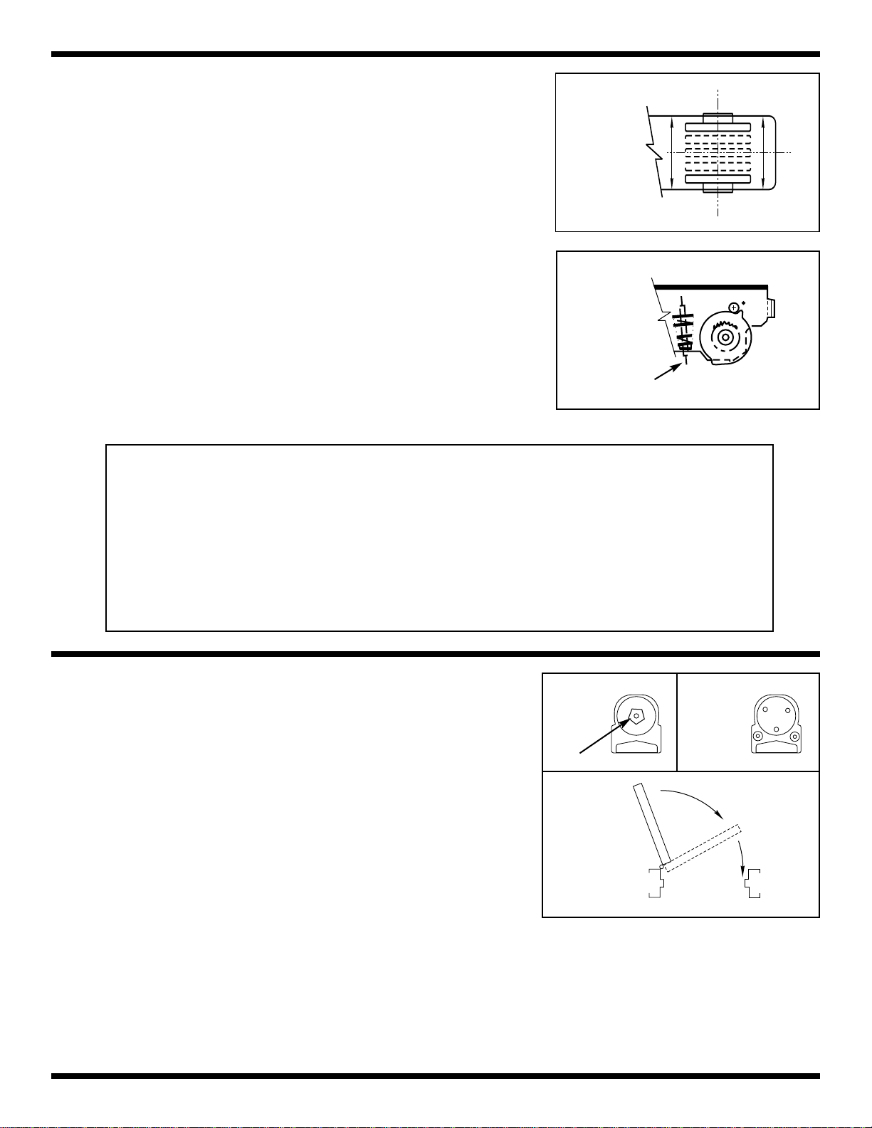
4. Making Adjustments to the Holder
A. Closer spring force should be as low as possible.
(Closer should arrive at lowest setting).
B. Turn OFF Power (using ON/OFF switch).
C. To set Hold Open:
1. Door should be in CLOSED position.
2. Raise or lower cam until the word “Pull”is dis-
played from the UNDERSIDE of the unit (Fig 4a).
3. Open door to desired Hold Open position.
4. Raise or lower cam and ROTATE until pocket of
cam is in position next to Roller A shown in Fig 4b
5. Release cam to re-engage teeth.
6. Turn ON power (using ON/OFF switch).
7. OPEN DOOR. Door should stay in Hold Open
position–if not, repeat Steps 3 and 4.
8. Pull door OUT of Hold Open–door should close
freely.
9. OPEN DOOR. If releasing force needs to be
increased, turn adjusting nut IN. If lesser holding
force is desired, turn nut OUT.
Trouble-Shooting Tips:
1. Turn ON power.
2. Can door swing far enough to engage hold open? Minimum opening is 85°.
3. Make sure closer is at lowest spring setting.
4. Put piece of metal against the magnet to make sure it is receiving current.
5. If not, double check wiring instructions.
6. If so, with door in closed position look up at holder mechanism. Word PULL should be visible, if
not, adjust cam.
7. Turn adjusting nut.
8. Check arm indexing.
5. Closer Adjustments
A. Manually pull door out of Hold Open.
B. If closing force is too weak, turn adjusting nut on end of
closer (Fig 5a) clockwise.
C. Put door in Hold Open position.
D. If door does not stay in Hold Open, re-adjust closing
force until door latches but the force of the closer
does NOT pull door out of Hold Open.
E. Adjust closing speed. (Fig 5b)
F. Adjust latch speed. (This speed should be slightly
faster than closing speed.)
G. Attach covers to closer and holder with screws provided.
Page 4
ISFM0600
Closing
Speed
Latching
Speed
LS
Fig 5a Fig 5b
Fig 5c
Use 1/8 Allen Wrench
Fig 4a
Fig 4b
Hold Open
Adjust Nut
Spring Adjusting Nut
www.rixsondoorcontrols.com
Pull Side Mounting
Popular Safety Equipment manuals by other brands

Lanex
Lanex PB-20 instruction manual

SKYLOTEC
SKYLOTEC ANCHOR ROPES Instructions for use

Besto
Besto Buoyancy Aid 50N Instructions for use

TEUFELBERGER
TEUFELBERGER NODUS Manufacturer's information and instructions for use

Troy Lee Designs
Troy Lee Designs Tbone Product owners manual

Innova
Innova Xtirpa Instruction and safety manual

bolle SAFETY
bolle SAFETY B810 quick start guide

SHENZHEN FANHAI SANJIANG ELECTRONICS
SHENZHEN FANHAI SANJIANG ELECTRONICS A9060T instruction manual

Hiltron security
Hiltron security POWER8E Installation and use manual

Salewa
Salewa MTN SPIKE user manual

Hatco
Hatco B-950P installation guide

Sitec
Sitec TX MATIC operating manual


