Rizzoli M Series Quick start guide

M - MZ - ML RANGE
Operational Manual for USA/Canada

2

3
The use of economic and ecologic combustibles, the sweet warm of natural fire, the sweet fragrance of the
wood of our forests are the qualities that make indispensable wood fired cookers in every house.
Your choice fell upon a Rizzoli cooker, result of a tradition started in 1912 when Carlo Rizzoli began the
production of wood fired cookers with the typical style of the valley in the dolomites. Year after year Rizzoli
continued to refine its cookers using even more advanced technologies, but without losing contact with the
elegance, the beauty and the functionality of the original product.
1. INSTRUCTIONS
1.1 GENERAL INSTRUCTIONS
For the perfect working of Rizzoli cookers it is necessary the correct placing and connection to the chimney
and to the heating system if it is necessary. The installation normally ends when you light the cooker. It is
necessary to predispose a duly made chimney and well suited to the model you chose. Before the connection
of the cooker it is necessary to contact a local chimney sweeper. The installation usually ends with the lighting
of the cooker and the verify of the correct working.
It is necessary to use well dried and good quality wood: it is also necessary to sweep the chimney and the
cooker regularly.
We recommend to read carefully the instructions in this booklet before starting to use the cooker.
Keep this booklet because it could be useful in case of necessity. Talking about the working and the
installation of Rizzoli cookers, all the European/USA/Canadian laws, national and local laws and rules must
be respected.
1.2 SAFETY INSTRUCTIONS
• Respect all the safety distances during the installation of the device.
• The grids and the ventilation holes of the device must not be obstructed during the installation or the use
of the device.
• Extracting fans, if working in the same room where the device is installed, might cause problems when a
correct ventilation is not guaranteed.
• The installation must guarantee the possibility of access to clean the device, the flue outlet, the chimney
hood and for the maintenance of the hydraulic components.
• When using the cooker, some parts of the device may be very hot, keep attention not to lean and not to
touch by hand hot parts (frame, plate and doors).
• When you cook and generally when you use the cooker you must not wear flammable dresses.
• Keep more attention in presence of children.
• Do not place on the device flammable or explosive materials, in particular curtains or do not place near
flammable chemicals and aerosol cans.
• The fire door must always be closed except for lighting operations, fire feeding operations and during the
maintenance operations.
• Do not open the fire door when the cooker is working and in presence of flame.
• The loading of an excessive amount of wood may overheat the device and generate damages to things or
persons.
• Check regularly the gaskets, the carbon and ash residuals inside the cooker, the in the fume circuit and in
the chimney connection.
• Check regularly the fume-circuit and, the chimney connection and the chimney itself. At least every six
months of normal use contact an experienced technician for checking and cleaning the device.
• The plate must be cleaned regularly according to necessities after every use and make regularly the specific
maintenance.
• Before you go away for a long time, be sure that the fire is terminated.

4
• The first lightings of the cooker and the first seasonal lightings must be done with temperate fire in order
to prevent possible breakings of the internal parts.
• After a long period in which you do not use the cooker, check carefully that obstructions are not present
and that the cooker works regularly.
• Use only original or authorized spare parts.
• Do not make any unauthorized modification.
1.3 RECOMMENDED COMBUSTIBLES
Wood fired cookers are built to use wood for burning. We recommend to use good quality wood, dry,
seasoned and split.
Using good quality wood is warranty of good heating power and avoid the forming of carbon residuals and
soot. To avoid dissipation of energy and eventual deforming and damaging processes you must not use
excessive combustible (see paragraph 6.1).
Burning an excessive amount of wood can cause the sudden ignition of flammable gases, with the risk of
causing damage to things and people.
WARNING!
Painted part of the cooker could change colour if the temperatures in the
combustion chamber are too high. The causes could
be the excessive wood loading or the
use of not correct combustibles. This damage is not covered by warranty.
1.4 OTHER COMBUSTIBLES
The use of pre-compressed trunks and coal is not allowed, because the strong heating produced may damage
the internal refractors, the wood-carrying grill, the oven and in general all the parts directly exposed to fire.
Other combustibles and refuses, for example plastic, enamelled or treated wood or carton must not be
burned. Using this materials cause serious damage not only to your health and environment but also to wood
fired cooker and chimney. The cooker must not be used as incinerator. It is recommended to use only the
suggested combustibles and not liquid fuel.
1.5 PARTS OF COOKERS
Picture 1
1
Riser
7
Starting air regulation
13
Flame keeper
2
Frame
8
Plinth
14
Primary and secondary air
3
Side
9
Woodbox
regulation
4
Starting lever
10
Oven door
15
Plate
5
Fire door
11
Oven door glass
16
Disc or circles
6
Door opening lever
12
Oven thermometer

5
Picture 2
1
Riser
7
Starting air regulation
13
Flame keeper
2
Frame
8
Plinth
14
Primary and secondary air
3
Side
9
Woodbox
regulation
4
Starting lever
10
Oven door
15
Plate
5
Fire door
11
Oven door glass
16
Disc or circles
6
Door opening lever
12
Oven thermometer
1.6 ACCESSORIES
Together with the wood fired cookers Rizzoli you will find some accessories that simplify the installation, the
maintenance and the daily use of the device.
• Ash drawer
• Glove
• Poker
• Scraper
• Oil for the care of the plate
• Cleaning oil for the plate
•
Abrasive sponge
• Sponge for fire door cleaning
• Devices for the connection of the exhaust
-pipe
• Grill for the oven
• Baking
-pan
• Instruction booklet for us
e and maintenance
• Green booklet and warranty certificate
• Quality certificate of the refracto
ry bricks

6
2. INSTALLATION
2.1 GENERAL NOTES
Wood fired cookers are easy to install; anyway you must take some cares to avoid damages due to
unskillfulness. Before the installation, we recommend to verify the necessary space, the safety distances, the
correct predisposition of the chimney and the possibility to make the necessary connections.
Do not drag the cooker, move it keeping it lifted from the floor. The device must not be moved making effort
on the handrail or on the handles.
2.2 SAFETY DISTANCES
Be sure that the cookers that have to be framed has the minimum safety distances to flammable or high
temperature sensible materials, see table 2.2 (T). Rizzoli also produces spacer to reduce distances. If the
cooker is framed between not sensible to heating materials, it is necessary anyway to keep a minimum
distance of 0.08” - 0.12”(2 - 3 mm) to allow the dilatation of the materials when the temperature changes.
The device must be placed on a floor with enough load capacity. If the existing building does not satisfy this
condition, you must adopt different solutions (for example you can use a plate to distribute the load). In
case of floor made with flammable material, it is necessary to use a fireproof protection for the floor in
front of the fire door. The cover of the floor must extend for 18”(46 cm) minimum in the front part and 8”
(20.32 cm) minimum over the fire door on the sides. We suggest not to install furniture on the top of the
stove. Eventually, the resistance of the furniture to heat must be guaranteed, in this case you must respect
a minimum distance of 36”(91,44 cm) from the plate. In case you want to use an aspiring hood, it is
absolutely necessary that it is resistant to high temperatures. Rizzoli is specialized in the production of
aspiring hoods to be used together with the wood fired cookers. During the installation, you must be sure
not to obstruct the ventilation holes on the top: this to prevent the decadence of the isolating properties of
the device and, in general, of its correct working.
Picture 3 - Minimum safety distances when using suited spacers (wall and sides protector or non combustible materials) for the
installation into furniture.

7
2.3 CHIMNEY
Chimney has a main importance for a correct working. Wood fired cookers are built to insure the maximum
efficiency, anyway the performances of the cooker are deeply influenced by the chimney. If the chimney has
defects or does not match the building laws, it is not insured the correct working of the device. To build the
chimney you must use suitable materials, made to work with high temperatures and according to fireproof
laws: it is not important the kind of material, on condition that it is right and that the chimney is isolated.
Contact a specialized technician or a local chimney sweeper for any problem dealing with the chimney,
chimney hood and connection to cooker.
Picture 4 - Components of the chimney. A= cooker, B= conjunction, C= flue, D= chimney, E= reflow zone
2.4 DIMENSIONS AND CORRECT FORMS OF CHIMNEY
Picture 5 - Samples of correct and incorrect chimney connection.
8
Chimney must be dimensioned in a correct way according to the type of cooker it is connected with, minding
the environmental and general conditions of the place in which it is placed. The section of the chimney must
permit the flow of the fumes produced by the cooker without difficulties, but it must not be too big otherwise
the chimney will experience problems in heating itself and this may generate problems like weak draught
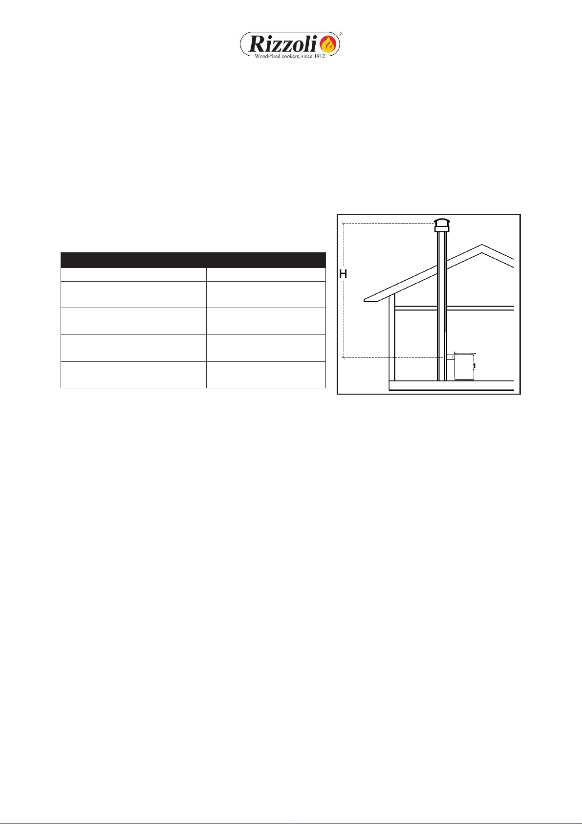
and condensation. In table 1 it is indicated the recommended diameter for the flue according to the model
of device and to the height of the chimney (H). The height of the chimney must be enough to insure the
draught necessary to the chosen model. Bigger is the height of the chimney, bigger is the draught; if the
chimney is lower than 4 metres, the correct working of the cooker is not insured. The chimney must not have
tortuous parts, horizontal parts or counterslope parts; the number of bends must be reduced to minimum.
In picture 5 you can see some examples of good and bad chimney connection.
Table 1 - Indications for the dimension of the chimney according to its
height.
Model
M - MZ - ML RANGE
ø entrance
5,51” (140 mm)
ø flue
H < 13,2’(4 m )
Draught not guaranteed
ø flue
13,2’(4 m) < H < 19,7’(6 m)
7,09” (180 mm)
ø flue
H > 19,7’(6 m)
6,3” (160 mm)
Necessary
chimney draft
12 Pa
(0.0482 wc)
Picture 6 - H dimension for the sizing of the flue.
2.5 CHIMNEY FLUE
The flue must be well isolated and circular if possible. The flue must not have defects, narrowings or losses.
All the inspection doors must be closed and well sealed. The connection of other devices to the same chimney
is not allowed.
2.6 CHIMNEY POT
The chimney pot must have an exit section doubled than the one of the chimney, in order to make easier the
exit of the smoke. The chimney pot must be enough tall to lean out over the reflow zone generated by the
roof: if you are not sure about this contact experienced technicians. If you are in a windy place, it might be
necessary to install windproof devices.
The chimney should extend at least 3 feet above the roof surface it penetrates and 2 feet higher than any
roofline or other obstacle within a horizontal distance of 10 feet.
2.7 STOVE PIPES CONNECTION
The connection of the cooker to the flue must be as short as possible and must not have horizontal or not
much inclined parts. The counterslope parts are forbidden and must be absolutely avoided. Near the
conjunction, flammable materials must not be present. The conjunction must not go inside the flue. To
increase the safety of the conjunction, we suggest to install a washer on the wall being sure that the
connection between the washer and the chimney is walled and well sealed. Also all the connection must be
fixed and sealed. Connections through wall, ceiling and floor ( see Part 2 Installation instruction).
9
2.8 FLUE OUTLET POSITION
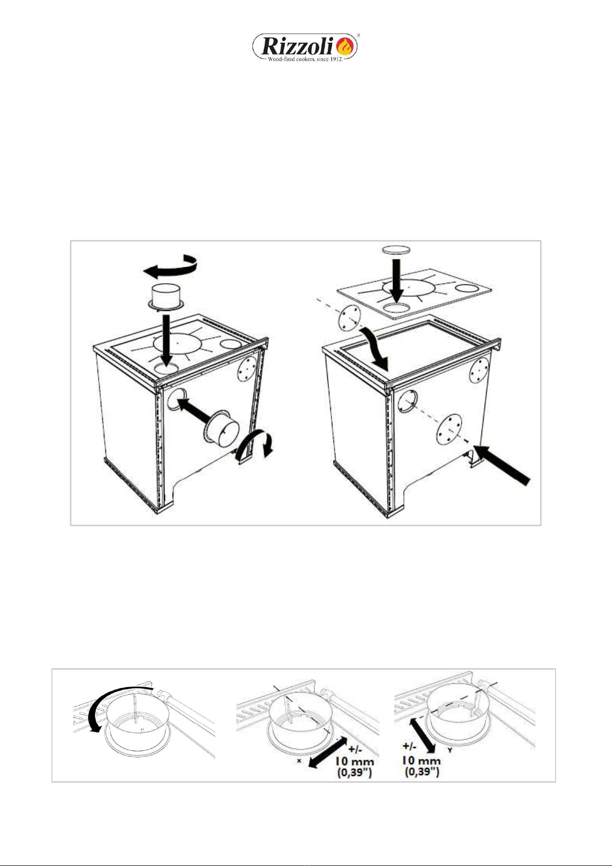
M-MZ-ML Range models are endowed with the predisposition of the flue outlet in the upper and rear parts,
right or left. The choice of the side must be done when ordering the cooker. After the delivery, it is still
possible to change the position from right to left and from left to right but it is necessary to make some
variations inside the cooker in addition to the replacement of the flue connector. The variation must be done
by experienced technicians.
The use of the flue outlet upper or rear is free and can be chosen by the installer. Before connecting the
cooker, it is necessary to chose the correct outlet and to verify that the other outlets are closed, eventually
using the caps given as endowment of the cooker.
Picture 7 - Multiflue cooker, predisposition of the correct flue outlet.
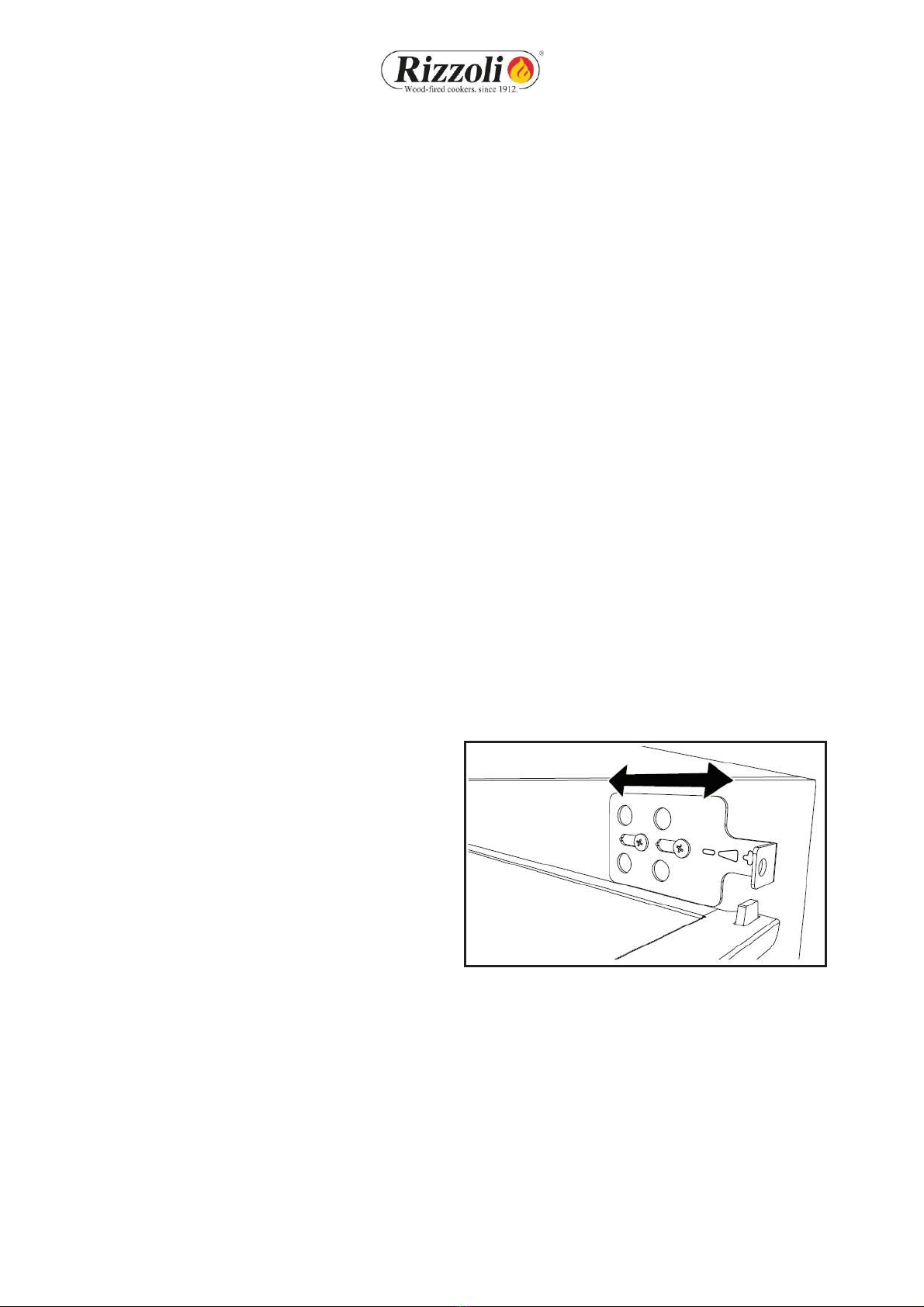
2.9 CORRECT CONNECTION TO THE CHIMNEY
If the conduct of the chimney starts from a lower floor than the connection point of the device, it may be
necessary to close the conduct under the connection pipe with fireproof materials. If you have the chimney
behind or up, you have to use the connector with bayonet coupling. This must be inserted and turned so that
it can remain blocked. This connector has a tolerance of about 1 cm (0,39”) to make the installation easier.
The tolerance is available according to a single direction which depends on the orientation of the connector
(see picture 8).
Picture 8 - Tolerance for flue outlet on the top and back. The tolerance depends on the orientation of the connector.

10
The connection with the chimney must be always well fixed and sealed, it must not have narrowing and must
not decrease the usable section of the chimney (see picture 9). If near the cooker there is flammable material
or high temperatures sensible, the connection must be isolated and the safety distances must be strictly
observed.
Picture 9 - Examples of correct and incorrect connection of the chimney.
2.10 AIR INTAKE
The standard installation of the wood fired cooker considers that the comburent air is taken from the room
where the device is installed through the air intake of the device located in the plinth. In this case, in the
room must be always ensured the recycle of fresh air, in particular if the room is small and window and door
frames are hermetic. The correct flow of air in the room must be ensured also in presence of other
combustion based devices, aspiring hoods, chimneys and vent-holes. The air intake in the room must have a
minimum surface of 80 cm2. On demand, Rizzoli can give specific valves which can allow the automatic
opening of the air intake only when it is necessary for the correct working of the device in order to warrant
a maximum depression of 4 Pa in the place of installation. The wood fired cookers can also be connected so
that the comburent air comes directly from outside. In this way, for the device it is not necessary another air
intake in the room of installation. To make this it is necessary to prepare a conduct connected directly with
the external part of the house and make a direct connection with the air intake of the device. The air intake
of the cooker is located inside the woodbox in correspondence of the combustion chamber. For the
connection, we suggest to use a flexible pipe.
Picture 10 - Installation with air intake in the room of installation and installation with air intake directly connected to the wood
fired cooker.
11
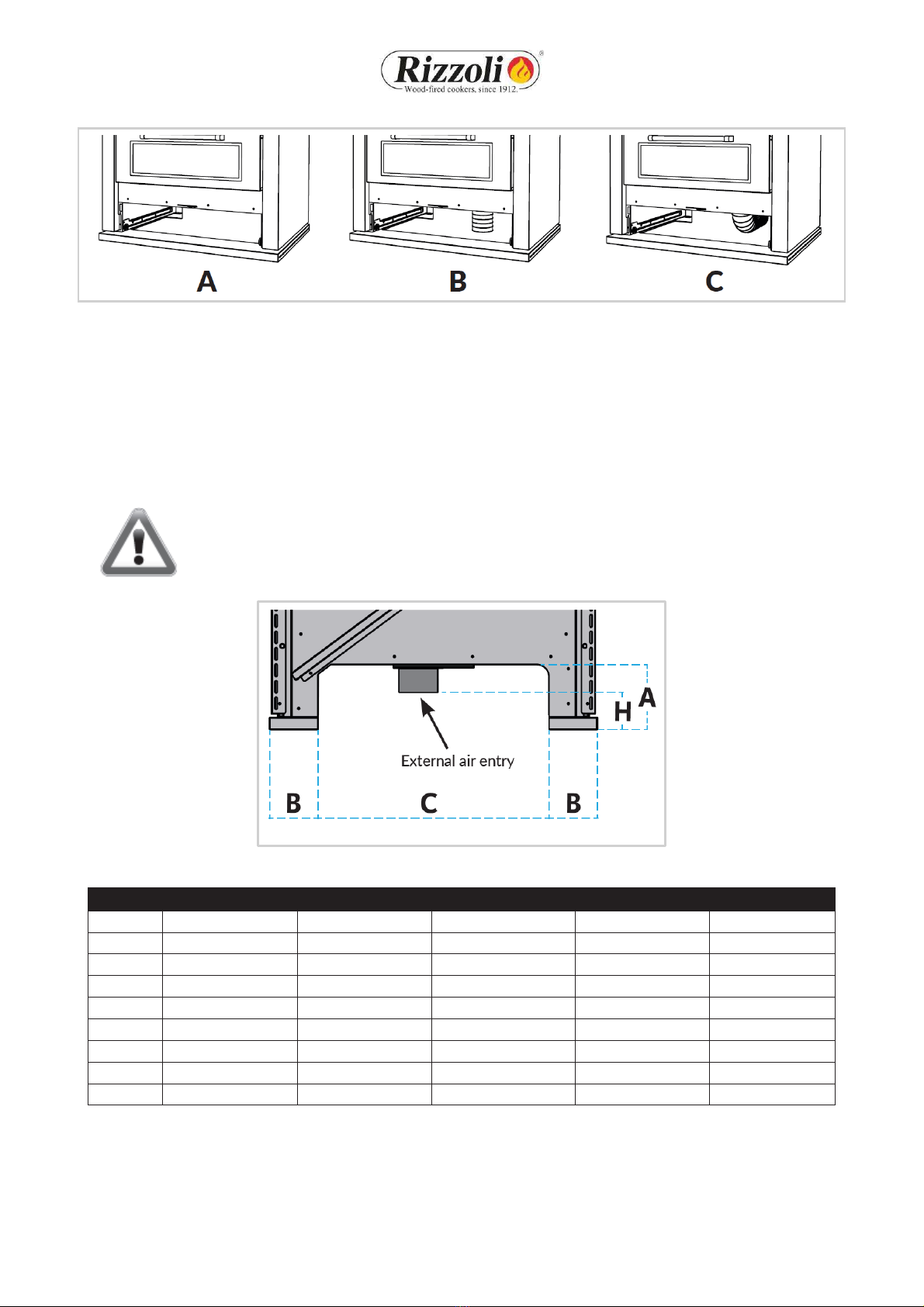
Picture 11 - Possible connections of the air intake of the cooker.
A= External air intake not connected, B= External air intake on the floor, C=External air intake on the wall.
To make the connection easier we suggest to make the external air intake on the floor in correspondence
with the internal part of the plinth, or on the wall through the rear part of the device (see table 2 and picture
12).
For ML Range wood fired cookers it is recommended to connect the external air intake to the floor but on
demand it is possible to have an optional item to make the connection to the wall.
Are also possible other solutions for the connection but they must be decided together with Rizzoli.
WARNING! Aspiring hoods or extracting air fans in the room may generate problems to
the device if there is not a suited air intake or in case of air intake sub-dimensioned.
Picture 12 - Rear sight of the plinth of the wood fired cooker and specifies for the connection with the air intake.
Dimensions
Models
A
B
C
H
ø
M 60
6,22” (158 mm)
4,64” (118 mm)
14,33”(364 mm)
4,72” (120 mm)
3,74” (95 mm)
M 70
6,22” (158 mm)
4,64” (118 mm)
18,27”(464 mm)
4,72” (120 mm)
3,74” (95 mm)
M 80
6,22” (158 mm)
4,64” (118 mm)
22,20”(564 mm)
4,72” (120 mm)
3,74” (95 mm)
MZ 60
5,51”(140 mm)
3,66”(93 mm)
16,30”(414 mm)
4,72” (120 mm)
3,74” (95 mm)
MZ 70
5,51”(140 mm)
3,66”(93 mm)
20,24” (514 mm)
4,72” (120 mm)
3,74” (95 mm)
MZ 80
5,51”(140 mm)
3,66”(93 mm)
24,17”(614 mm)
1,02” (26 mm)
3,74” (95 mm)
ML 60
--
--
--
1,02” (26 mm)
3,74” (95 mm)
ML 80
--
--
--
1,02” (26 mm)
3,74” (95 mm)
Table 2 - Dimensions for the connection of the external air intake.
12
WARNING! For the correct working of the device verify that the passage of comburent air
is not obstructed or, in case of connection with external air intake, that the air aspiration
grill is not obstructed.
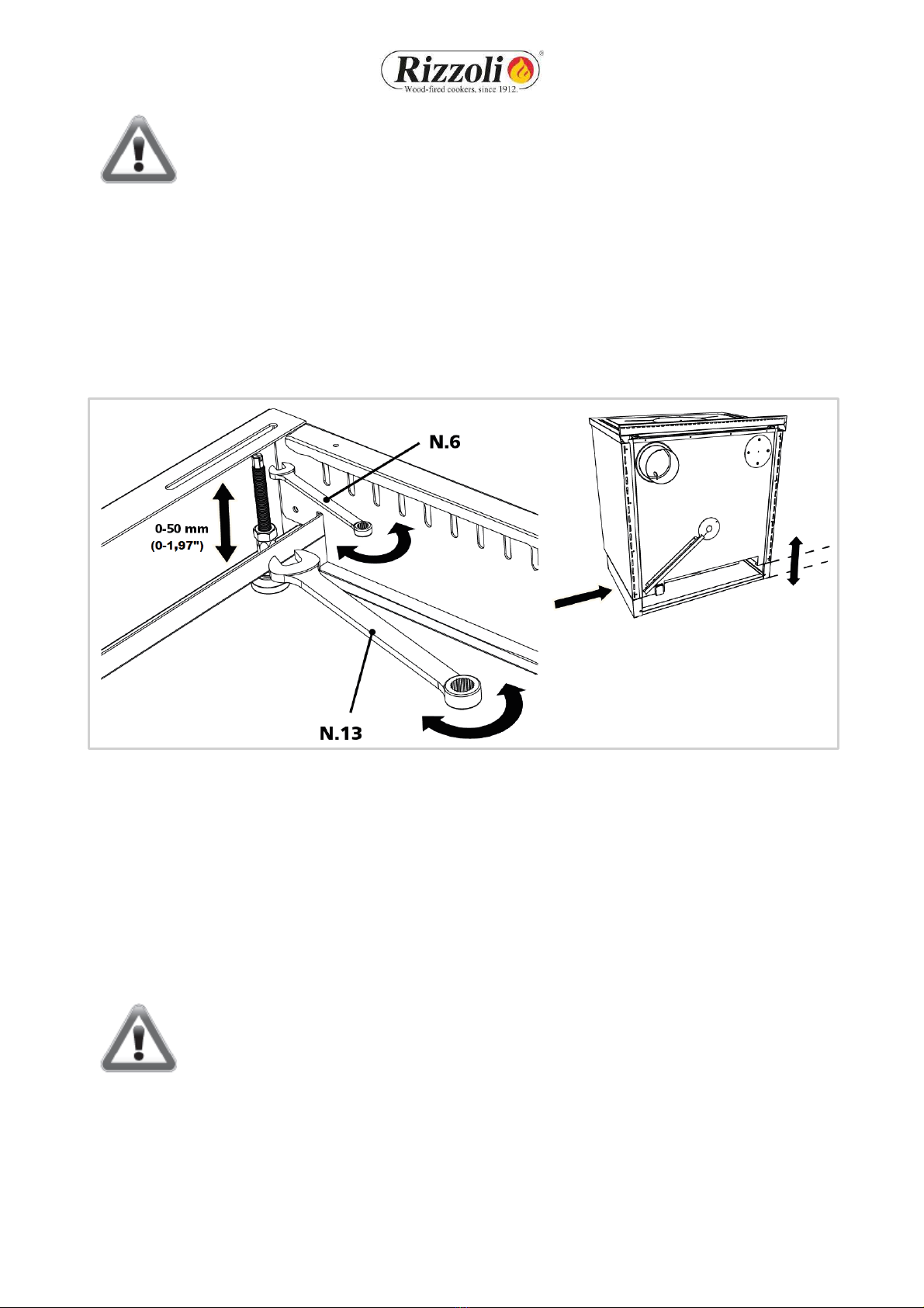
2.11 PLINTH REGULATION (MZ)
The plinth of MZ Range cookers can be regulated in order to match the space in which the cooker is inserted.
It is possible to adjust the level of the cooker by operating on the levelling pins that can be regulated in height.
To do this, it is necessary to remove the woodbox and regulate singularly each pin placed in the plinth near
the corners, so that the adjustment of the cooker is correct. For the regulation of the pins, use an hex key
n.6: once you have reached the desired height, fix the locknut with a n.13 key (see picture 13). The pins have
an excursion of 50 mm (1,97”).
Picture 13 - Regulation of the height of the cooker with hex key through the levelling pins
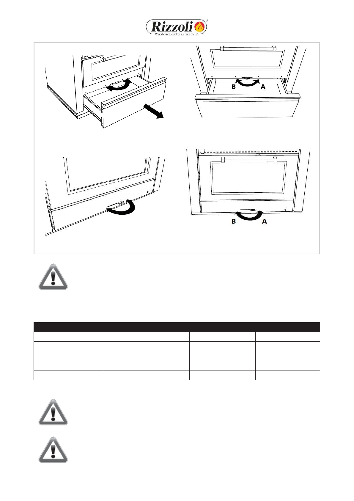
2.12 TELESCOPIC PLINTH REGULATION (MZ)
The wood fired cookers MZ Range have a special woodbox integrated with the plinth. In this case it is anyway
possible the regulation of the height of the plinth but not the regulation of the recess. The regulation of the
height of the plinth can be made in the same way as described in paragraph 2.11. After the regulation of the
pins, it is possible to regulate the sliding part of the plinth to cover the empty part: to do this, remove the 2
screws as picture 14 A and 14 B. Then, it is necessary to regulate also the height of the plinth integrated in
the woodbox. To do this, release the two screws on the woodbox, lower slowly the plinth then screw again
when the chosen height is reached (as in pictures 14 C and 14 D).
WARNING! For a correct installation it is necessary to keep about 10 mm (0,39”) between
the floor and the plinth of the woodbox.

13
Picture 14 - Regulation of the telescopic plinth.
2.13 DOOR OPENING VARIATION
M-MZ-ML Range cookers are predisposed with the rightwards fire door opening, if not indicated leftwards
at the order. It is possible to change the opening also after the installation. The operation must be done by
experienced people.
Picture 15 - Variation of the door opening direction.
2.14 FIRST LIGHTING
Before starting to use the cooker, remove the packaging materials in the oven and in the wood box, remove
the stickers and remove the plastic film in which is wrapped the plate and remove with a rag the most of the
oil on its surface. We suggest to make a first lighting of the device just to verify the correct installation. The
14
first lighting must be done with moderate fire, using little wood broken in small pieces. In the next lightings
you can progressively increase the load of combustible. During the first lightings some smell due to processing
residuals might happen. This phenomenon is normal, it requires the ventilation of the room and will
disappear quickly.
WARNING! During the first lightings of the cooker it is recommended to keep the oven
door open to allow the expulsion of eventual working residuals, otherwise the cooker
could suffer damages.
2.15 SETTLEMENTS
The refractory mortar used for the internal walling contains always a little moisture that is eliminated after
the first periods of use: so it is normal that the first times you light the cooker a little condensation is being
generated.
All the refractory materials inside the cooker experience a settlement process that may generate small
holes on the bricks, such holes do not preclude anyway the working of the cooker. Other settlements may
involve other parts of the cooker so during the heating and cooling phases you might hear light noises.
These symptoms do not absolutely preclude the use of the cooker and fading out till disappearance with
the constant use of the cooker.
3. USE
3.1 WORKING OF THE COOKER
During the operation, inside the cooker happens a combustive reaction of combustible (the wood inserted
in the combustion chamber) and burning (the oxygen present in the air of the room in which the cooker is
placed).
The wood fired cooker makes an intermittent combustion: after the lighting, the combustion goes on till the
exhaustion of the combustible but it can be maintained lighted by making another load of combustible and
so on.
The maintenance of the combustion in time is guaranteed by the correct working of the chimney, which
allows to evacuate the fumes and in the same time to feed the flame with comburent air. In this way, the
features of the chimney have a big influence on the correct working of the device.
The combustion of wood requests that the air flow inside the combustion chamber happens in different
points to obtain the maximum efficiency. In particular, it is present a primary air feeding that flows in the
lower part of the combustion chamber by the grill, and one or more secondary air feedings that flow in the
upper part of the combustion chamber.
The primary air is the main air and regulates the combustion speed.
The secondary air allows the post-combustion of the fumes, generating further heating, knocking down the
amount of harmful gas and so improving both the rendering and the impact on the environment.
Once started the combustion it cannot be interrupted in a safe way: it must be always faded out naturally
with the exhaustion of all the combustible inserted.
WARNING
!For a correct operati
on verify that the eventual external air intake in the room
and the air aspiration and ventilation grids are not obstructed.

15
3.2 STARTING
To allow an easier lighting of the cooker with cold
chimney, the M-MZ-ML Range wood fired cookers have
two devices useful for starting. The starting key is ruled
by a rod: extracting the rod, the key opens. This creates
a direct connection between the combustion chamber
and the chimney, in order to obtain an improved
draught. The regulation of starting primary air allows the
direct entrance of air from the room in which the cooker
is installed to the combustion chamber. When starting,
it is suggested to open both the devices that later shall
be closed when the fire will be started for the normal
working of the cooker. The cooker is designed to be used
with the starting regulations closed, using they in
different ways does not allow to the cooker to work at
its maximum and may cause damages.
To light the fire, you can use as combustible well dried
wood, broken thin, together with the products available
in commerce. The combustion might be difficult as far as
the chimney is cold. The necessary time depends on the
chimney and the weather conditions.
Picture 16 - Regulation of starting primary air.
Picture 17 - Starting key. With lever outside, the key is open and the starting is easier; with lever inside the key
is closed for the normal working.
WARNING!
All handles and regulators might get hot! Please use included glove!
WARNI
NG! It is
important that the wood starts to burn quickly. The lighting of a big amount
of wood in starting phase can cause an excessive production of smoke and a quick gas
emission with consequent damage to the stove.
3.3 AIR REGULATION
The air flow is ruled by an apposite valve ruled by a lever placed below the oven door. The valve is closed in
the left position, is open in the right position. The position of the valve rules the comburent air inflow: more
it is open, faster will be the combustion and bigger will be the power of the device. When the cooker is not
working the primary air must be closed, in order to limit the undesired air flow that may cause an anticipated
cooling of the device and the room. This operation is particularly important when the external air intake of
the cooker is directly connected. Generally, for the good working of the device, we suggest to follow the
indication for the regulation of air reported in table 3.
16
Picture 18 - Regulation of the air intake lever (M-
MZ Range).
Picture 19 - The valve is open in correspondence of the
position marked by letter “A”, while
is closed in the position
marked with letter “B” (M-MZ Range).
Picture 20 - Regulation of the air intake lever (ML Range).
Picture 21 - The valve is open in correspondence of the
position marked by letter “A”, while
is closed in the position
marked with letter “B” (ML Range).
WARNING!
All handles and regulators might get hot! Please use included glove!
The open position is indicated when the device is working. It allows the entrance of the combustive air
necessary to feed the flame. The cooker cannot work with the lever in closed position.
Condition
Air regulation
Starting air
Starting key
Starting
Open
Open
Open
Fast cooking
Open
Closed
Closed
Slow cooking
Half open
Closed
Closed
Fast heating
Open
Closed
Closed
Slow heating
Open at minimum
Closed
Closed
Table 3 - Cooker regulations in the different use conditions.
WARNING
!When
loading wood, consider a gap of few millimetres between wood and
glass, in order to avoid overheating of the glass that could cause breakings.
WARNING!
Do not open the fire door during combustion, as otherwise smoke may escape.
The
cooker is designed to be used with the closed fire door.
17
3.4 PLATE COOKING
The radiant plate is designed to allow a fast and simple cooking. The hotter part is situated in correspondence
with the hotplate, this is the best part for placing a pot which must get warm quickly. The external parts of
the plate are better to keep foods warm. To obtain the maximum cooking speed you have to use broken and
thin wood and make the regulations as described in the previous chapters. The plate must not be overheated
and made red hot because in such way the device may experience damages without having no advantage for
the cooking of foods.
3.5 OVEN COOKING
The internal temperature of the oven depends on the combustion speed and on the amount of combustible
used. In particular, working on the lever of the air intake and so on the speed combustion, you can obtain a
more steady combustion in order to avoid sudden changes in temperature inside the oven. If you want to
heat the oven starting from the device, we suggest to increase the temperature with bright fire and then to
decrease the speed combustion to keep the temperature steady. The cookers are endowed with fire door
with glass and thermometer that makes easier the temperature controlling operations; the temperature
indicated by the thermometer is approximate ad is useful only for the cooking of foods. If you want to brown
the meals, you should keep them in the upper part of the oven: instead, if you want to cook in a steadier way
you should keep the meals in the centre. When you do not use the oven, we suggest to keep the oven’s door
slightly open in order to let the heat go outside the cooker: an overheating can damage the cooker.
For example, to cook the spineless person biscuits in a correct way, it is necessary the pre-heating of the oven
at a temperature indicated on the thermometer of 150°C (302°F), keeping it in temperature by adding more
or less 1 Kg (2,2 lbs)of wood for every charge as the reaching of the coals. Once the temperature becomes
stable, insert the baking-pan with the biscuits in the central position in the oven for 10 minutes, then extract
the baking-pan, rotate it and reinsert it again in the central position for other 5 minutes. In the end, remove
the baking-pan from the oven and leave cool the biscuits.
3.6 STEAM EXCESS VALVE
Cooking meals sometimes may generate a steam
excess inside the oven. For this reason on M-MZ-
ML Range models there is a valve that allow to
eject the steam in excess. The valve is placed inside
the oven on the lateral side towards external and
when necessary it shall be regulated to open the air
intakes. To avoid possible burns, it is
recommended to regulate the valve only before
the lighting of the cooker.
Picture 22 - Steam excess valve.
3.7 HEATING
Wood fired cookers may be used also to heat the ambient in which they are installed. The heating comes
from the plate and from the front of the cooker. So the heating is effective just in the ambient in which the
cooker is inserted and in particular near the cooker itself.
Also for the heating of an ambient you have to start the cooker with bright flame without using too much
woo d as long as a bed of cinders is created: at this point you can put more load of combustible inside the
combustion chamber. For a bigger autonomy of the cooker we suggest to use wood cut in big pieces, hard if
possible (ash-tree, beech, hornbeam and others) and to make the regulations as described for the slow
heating.
18
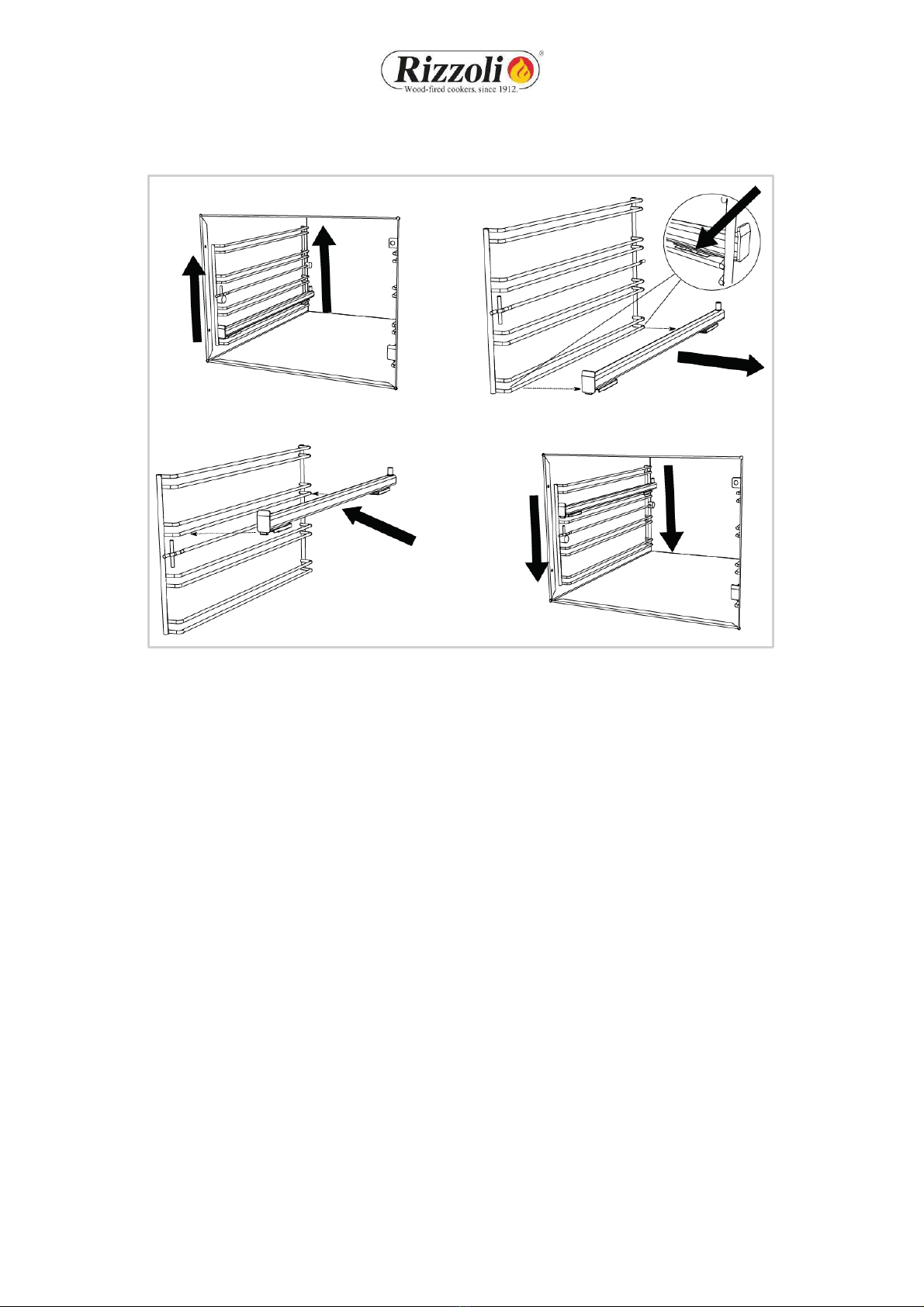
3.8 TELESCOPIC PULLOUT FOR BAKING PAN
Picture 23 - Instructions for the variation of the position of the telescopic pullout.
All the wood fired cookers have a telescopic pullout for endowed baking pan system. In this way, it is possible
to extract the baking pan without the necessity to sustain it, ensuring a better practicality. The telescopic
pullout is placed in a single position inside the oven, in the upper position. Only on ML cookers this can be
modified and moved to the lowest position or in the positions middle superior and superior. The process to
modify the position of the telescopic pullout is indicated in picture 23. Anyway, on all the cookers it is possible
to insert the baking pan without the telescopic pullout.
3.9 WOOD BOX (M - MZ)
The wood box has a slide scroll system that allows an assisted closure. When pushing the box, it will close
automatically.
For cleaning and for other reasons it could be necessary to remove the wood box. To make this you have just
to extract the box as the end of its track, then lift it softly and at the same time extract it again. To set the
box to the initial position, repeat the same operations inverted.

19
3.10 FIRE DOOR PROTECTION (OPTIONAL)
On M-MZ-ML Range cookers it is possible to have
on demand a steel protection which could be
placed on the fire door. This protection is
designed to shield the door when the cooking
operations require the continuous presence of
the user in front of the cooker or in presence of
children. In the other situations the use of the
protection depends on your discretion. The
placing operations must always be done with cold
cooker opening the fire door and placing the
protection on the door by joint.
Picture 24 –Fire door protection.
3.11 PLATE COVER (OPTIONAL)
On every cooker it is possible to use a stainless steel plate cover, made to cover the plate in the periods in
which the cooker is not used. In this way you obtain an uniform desktop. The plate cover must be used with
cold cooker. Before placing it, be sure that is not present humidity, that the plate is clean and that all the
necessary maintenance is done.

20
4. MAINTENANCE
4.1 CLEANING
The device works better if all its parts are without combustion residuals, a clean device will be less exposed
to problems due to wear. Cleaning frequency depends on how much and how the device is used, as well as
combustible quality.
WARNING! All these operations must be done with cold cooker.
4.2 CLEANING THE VISIBLE PARTS
Stainless steel parts have to be cleaned cold with neutral detersives or with a specific solution for stainless
steel in case of hard to remove dirt. Do not use at all abrasive sponges that may scratch the surface. Dry with
a soft rag, following the glazing wise.
In particular situations, after the installation or with the cooking of meals, an oxidised superficial stratus may
be generated, in particular on the inox stainless steel frame. Also in these situations, an accurate cleaning
will restore the state of the product as it was new. On request Rizzoli gives specific products to clean stainless
steel. For enamelled or painted parts, do not use abrasive or aggressive solution and in case of stains pour
some oil and wait while it absorbs the halo, then clean with a soft rag. It is also recommended to avoid the
use of solvents or denatured alcohol on painted parts.
4.3 GRILL CLEANING
Every time you use the cooker you have to clean the wood carrying grill before, at least you have to clean the
more rough deposits: the holes of the grill should not be obstructed. To make this you can use the poker
given together with the cooker. If the grill is not well cleaned, the flame could not be well feed and so you
could experience an irregular combustion. If the grill is being removed, it must be placed in its housing with
the flat part turned upwards.
4.4 ASH BOX
Every time you use the device you have to check the ash box located under the combustion chamber. When
the box is full, you have to empty it. If you do not empty it, the ash accumulates itself and makes the cleaning
more difficult. In case of excessive cinders the flame could not be well fed and you could experience an
irregular combustion.
4.5 OVEN CLEANING
The oven must be cleaned with apposite products available in commerce, to make this operation easier you
can remove the oven door. To make this you have to open the oven door and raise the tongues located on
the door’s hinges. Now, you can unhook the door from the cooker closing it softly and lifting the lower part
of the door. To hook again the door to the cooker, make the same operations reversed. Also the grids on the
sides could be removed to make the cleaning more simple.
Other manuals for M Series
1
This manual suits for next models
10
Table of contents
Other Rizzoli Cooker manuals


Popular Cooker manuals by other brands


Brandt
Brandt KV368WE1 operating instructions

Falcon
Falcon 90 Induction U109988 - 02 User guide & installation & service instructions

Tricity Bendix
Tricity Bendix U30352 SE558 user manual

Smeg
Smeg FS67MFX instruction manual

Indesit
Indesit KD3E1/G Instructions for installation and use

Bosch
Bosch HKN31 0 Series user manual


