RKC INSTRUMENT LE100 Operating and maintenance instructions

General Description
LE100
Features
Specifically designed for the measurement of liquid chemical levels.
The specific gravity compensation function eliminates the need to set liquid level with actual liquid and is easily accomplished during chemical
change.
The LE100 measures liquid levels by supplying inactive gas at fixed pressure to the sensor tube installed in the storage tank. Back-pressure is
determined by measuring the changing liquid level. The sensor tube pressure varies proportionately to changes in liquid level.
Level settings 6 or 8 points
Measuring range 0 to 1000 mm
Selectable display units (mm, %, l, cc, Pa, KPa)
High repeatability 0.3% full scale
Specific gravity compensation
One - touch empty adjustment
One - touch span adjustment
Volume compensation
Digital communication (Optional)
Monitoring output (Optional)
Empty adjustment function can adjust the displayed low limit measured
value to the purge pressure at the end of the sensor tube exposed to
atmosphere.
Empty adjustment function
The high limit value is automatically computed and the liquid level is
displayed linearly by setting the specific gravity of the liquid and the low
limit measured value. If the specific gravity is known, the high limit
measured value can be set without presence of actual liquid.
Specific gravity compensation
The percentage value display within a 0 to 100% range is achieved by
setting the optional high and low limit adjustment points.
Specific gravity compensation
with actual liquid
The specific gravity and high/low limit measured values are computed
automatically and the liquid level (mm) is displayed linearly by inputting
two optional points of actual liquid levels.
Span adjustment function
1LE100_01E
R
R
LE100
Back-pressure Level Meter
LE100
Low limit measured value
Chemical liquid
Specific gravity
1.1
LE100
Low limit measured
value
High limit measured
value
Level
Setting of specific gravity Low limit value setting
Set measured value ( mm )
LE100
Measured low limit
value
Measured high limit
value
LE100
Low limit value
High limit value
Specific
gravity
Setting
LE100
0%
100%
LE100
Optional adjustment
point for low limit
Optional adjustment
point for high limit
SET
SET
CE marked, UL/CSA Pending
(800) 576 - 6308
www.rkc-usa.com
Distributed By Inc,
RKC

Features
Liquid volume measurement
2LE100_01E
LE100
Back-pressure Level Meter
LE100 converts the change of back-pressure caused by the rise and fall of chemical liquid level into the actual chemical liquid volume for display in milliliters
(ml) or liters (l).
Automatic specific gravity compensation
The LE100 automatically compensates for specific gravity according to the number of times a semiconductor wafer is chemically-processed in the same tank liquid.
This illustration shows how the LE100 automatically adjusts specific gravity compensation between 1.10 to 1.20 through ten processing cycles.
The counting of wafer processing cycles can be entered manually at the front keypad with contact input or digital communication.
• When specific gravity is known
• When specific gravity is unknown
Empty adjustment Volume compensation
Volume compensation
Specific gravity compensation Measurement
Empty adjustment Specific gravity compensation with actual liquid
Measurement
LE100
LE100
LE100
Liquid volume in a tank with simple shape changes linearly in
relationship to liquid level. When the liquid volumes (ml/l) of optional
high/low points are set, the liquid volume measurement is accurately
displayed.
• When the tank has a simple shape
Liquid volume in a tank with a complex shape changes depending on
variations of the tank shape. The LE100 has up to 11 adjustment points
that compensate for these variations to linearize the displayed value
throughout the measurement range.
• When the tank has a complex shape
Liquid volume aml
at level A mm
Liquid volume bml
at level B mm
Low level A mm Liquid volume aml
High level B mm Liquid volume bml
The built-in linearizer has a maximum of 11 adjustment points.
Setting Setting
The built-in linearizer accurately
displays liquid volume at any level.
Not processed The first time The 2nd time The 10th time
Specific gravity: 1.100 Specific gravity: 1.110 Specific gravity: 1.120 Specific gravity: 1.200
LE100 LE100 LE100 LE100

Specifications
Inputs Outputs
Level setting
Performance
Empty adjustment
General specifications
Number of inputs : 1 point
Input medium : Non-corrosive gas
Input pressure range : 0 to 9.8 kPa
Zero point revision range
:± 5.0% of full span
Sampling time : 0.2 sec
PV digital filter : 1 to 100 sec (No filter when setting 0)
(First order lag filter)
Number of set points : 6 points ( 8 points optional)
Setting range : Same as units and range.
Setting resolution : Same as PV. (See Units and range table)
Specific gravity compensation
Number of set points : 1 point
Setting range : 0.800 to 2.500
Setting resolution : 0.001
Volume compensation function
Number of set points : 2 to 11 points
Setting range : Scaling low limit to high limit.
Setting resolution : Same as PV. (See Units and range table)
•Settable when unit is lor ml.
•Linearization setting allows the LE100 to display a liquid volume value.
•Measuring accuracy can not be guaranteed if the setting extends over
the inflection point or if a 1mm level change is greater than 4.4% of the
total volume.
Specific gravity compensation with actual liquid
Number of set points : 2 points
Setting range : Scaling low limit to high limit.
Setting resolution : 1
•
A specific gravity compensation with actual liquid measurement determines the
liquid's specific gravity and allows calculation of either high or low limit values.
Display
Input display : 7 segments LED
(4 figures, green, height :7.6 mm)
Set display : 7 segments LED
(4 figures, orange, height : 7.6 mm)
Action display : Point LED (green, OUT1 to 8)
Unit display : Point LED (green, mm, %, l, ml, Pa, kPa)
Repeatability : ± 0.3 % of full span
Non-linear : ± 0.5 % of full span
Temperature characteristic
: Zero output : ± 0.04 % of full span / °C
Span output : ± 0.04 % of full span / °C
•
All performance characteristics have a measuring accuracy of ± one digit.
Through the use of the empty adjustment, the tube tip can cancel an
offset to an atmospheric open state.
Span adjustment function
Number of set points : 2 points
•The percentage value display within a 0 to 100% range is achieved by
setting the optional high and low limit adjustment points.
Automatic specific gravity compensation
•Automatic specific gravity compensation is achieved by defining initial
and final specific gravity settings and the number of processing times.
Output activation point then becomes constant despite varying specific
gravity.
Level setting with actual liquid
Number of set points : 1 to 6 points (1 to 8 points optional)
•Each output activation point can be set in relation to actual liquid level.
Number of outputs : 1 to 6 points (1 to 8 points optional)
Output action :
Process high, Process low, Deviation high, Deviation low
Setting range : Same as input range.
Deviation setting range
:
-
10 to 10 mm
Differential gap : 0.0 to 10.0% of span
Output timer : 0 to 600 sec.
Hold action : ON / OFF settable
Interlock : Settable independently for each output
Output type :
Selectable for each output either for ON or OFF at operation
Output : Open collector output 24V DC 50 mA
Hold function
Peak hold : Highest measured value is held
Bottom hold : Lowest measured value is held
•The Hold function is always operational.
•After the Hold function is confirmed by operator, it can be reset at the
front panel keypad.
•When instrument power supply is OFF, Hold data is not backed up.
Contact input (Optional)
Number of inputs : 1 point
•Auto-zero (empty adjustment) activation or incremental count of the number
of processing times.
Input type : Non-voltage contact input
a) OPEN : 500kΩor more
b) CLOSE : 10Ωor less
• Possible to be activated by open collector output.
Communications (Optional)
Monitor output (Optional)
Compliance with standards
Communication method
: Based on RS-485 (two-wire)
Synchronous method : Start-stop synchronous
Communication speed
:
2400, 4800, 9600, 19200 BPS (Selectable)
Bit configuration : a) Start bit : 1
b) Data bit : 7 or 8
c) Parity bit : Without, Odd or Even
d) Stop bit : 1 or 2
Maximum connection
: 31
Number of outputs : 1 point
Output : 0 to 2.5V DC (Load resistance : More than 1kΩ)
Input impedance : Less than 0.1Ω
Output data type : Process value
Output scaling :
Available to high and low setting
Output accuracy : ±0.3% of span
Ripple of output : ±0.1% of span or less than 1 mV (resistive load)
Output resolution : More than 10 bit
• CE marked pending
• UL recognized pending
• CSA certified pending
Supply voltage : 21.6 to 26.4V DC (Rating 24V DC)
Power consumption : Less than 130 mA
Memory backup : Backed up by EEP-ROM
Data retaining period : Approx.10 years
Insulation resistance : More than 20MΩ(500V) between measured
terminals and ground terminal
More than 20MΩ(500V) between power
terminals and ground terminal
Dielectric voltage : 1000V AC for one minute between measured
terminals and ground terminal
1200V AC for one minute between power
terminals and ground terminal
Power failure : A power failure of 30 ms of less will not affect
the control action.
Weight : Approx. 150g
Ambient temperature : 0 to 50°C (32 to 122°F)
Ambient humidity : 45 to 85% RH
Operating environment
:
Free from corrosive and flammable gas and dust.
R
R
LE100
3LE100_01E
Back-pressure Level Meter

Model and Suffix Code
LE100
4LE100_01E
Specifications
Contact input (DI)
Monitor output
Model
Number of outputs
Power supply
Communication
Waterproof and dustproof
Connector type
6 points
8 points
24V DC
Not supplied
External contact input
Not supplied
RS-485
Not supplied
Monitor output
Not supplied
Waterproof and dustproof (To be released soon)
10 pins type *1
16 pins type *1
Attached connector
Not supplied
For 10 pins type (Model code: W-BP-01-N or equivalent) *2
For 16 pins type (Model code: W-BP-02-N or equivalent) *2
6
6
8
N
5
N
1
N
1
N
1
1
2
N
1
2
LE100-
Model and Suffix Code
*1 When 8 output points, contact input or communication functions are selected, only the 16 pin connector is available.
*2 When using a connector (W-BP-03-N or equivalent) intended for monitor use, AWG # 28 ~ 22 wire is required.
Y
Specifications
Cable name
Connector type
Cable length
W-BP-
10 pins type, Power supply / Output connector
16 pins type, Power supply / Output connector
Monitor output connector
Unit : mm (1,000 to 10,000 mm, Specify every 1000 mm units) No connector on open end.
Model and Suffix Code
•Model code of connector without cable : For 10 pins type: W-BP-01-N, For 16 pins type: W-BP-02-N, For monitor: W-BP-03-N
0 1
0 2
0 3
000
000
1
2
48
48
3 100
44 44
Unit : mm
Pin number Description
1
2
3
T/R(A)
T/R(B)
SG/DI
DI
OUT1
OUT2
OUT3
OUT4
OUT5
OUT6
OUT7
OUT8
COM(
-
)/ 24V DC
COM(
-
)/ 24V DC
+24V DC
+24V DC
4
5
6
7
8
9
10
11
12
13
14
15
16
1
2
3
4
5
6
7
8
9
10
Communications
Contact input
Open collector
output
Power supply
Pin number Description
1
2
+
-
Monitor output
Power supply / Output connector Monitor output connector
Ground terminal
Tube connection screw
25 2545
+0.6
0
45
+0.6
0
25 25
•Panel cutouts
Fitting Tube
Tube connection screw : M5 X 10
Fitting : Recommended unit : One-touch fitting PC6-M5SUS (NIHON PISCO CO., LTD)
Quick-action fitting TS6-M5-SUS (Koganei Corporation)
Tube : Fluorocarbon resin tube φ6 x φ4
Screw size : M3 X 6
Panel thickness : 1 to 9 mm
1
3
5
7
9
11
13
15
2
4
6
8
10
1
3
5
7
9
2
4
6
8
10
12
14
16
Power supply / Output connector
16 pins type
10 pins type
16 pins 10 pins
Connector type
Monitor output connector
S2B-XH-A *2
Power supply / output connector
10 pins type : PS-10PE-D4LT1-LP1 *1
16 pins type : PS-16PE-D4LT2-M1 *1
•The fitting and tube shall be prepared separately.
*1 Manufactured by Japan Aviation Electronics Industry, Limited
*2 Manufactured by JST Mfg. Co., Ltd.
Set code
0
1
2
3
4
5
0 to 400 (1250) •High limit value is decided by the measurement of specific gravity.
0.0 to 100.0
0 to 360 •Decimal point is decided by the setting of decimal point position.
0 to 360 •Decimal point is decided by the setting of decimal point position.
0 to 9.807
0 to 9807
mm
%
ml
l
kPa
Pa
Unit Range
External Dimensions and Rear Terminals
Units and range
Cable
Back-pressure Level Meter
(800) 576 - 6308
www.rkc-usa.com
Distributed By Inc,
RKC
Other manuals for LE100
1
Table of contents
Other RKC INSTRUMENT Measuring Instrument manuals
RKC INSTRUMENT
RKC INSTRUMENT LE110 User manual
RKC INSTRUMENT
RKC INSTRUMENT CZ-100P User manual
RKC INSTRUMENT
RKC INSTRUMENT VGR-B100 User manual
RKC INSTRUMENT
RKC INSTRUMENT AF110 User manual
RKC INSTRUMENT
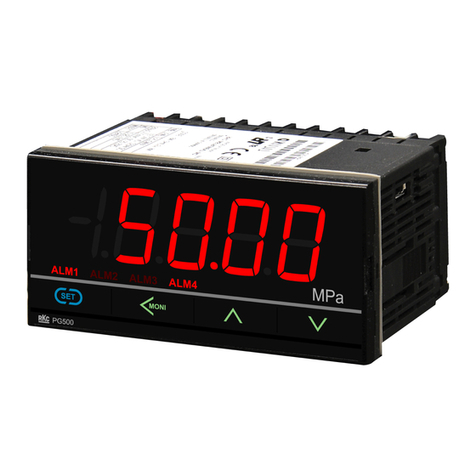
RKC INSTRUMENT PG500 Use and care manual
RKC INSTRUMENT
RKC INSTRUMENT CZ-100P User manual
RKC INSTRUMENT
RKC INSTRUMENT AE500 Manual

RKC INSTRUMENT
RKC INSTRUMENT AE500 Use and care manual
RKC INSTRUMENT
RKC INSTRUMENT LE100 Use and care manual

RKC INSTRUMENT
RKC INSTRUMENT VGR-B100 User manual
