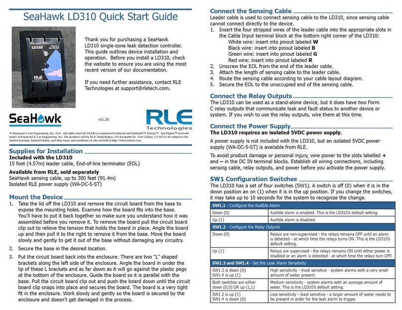
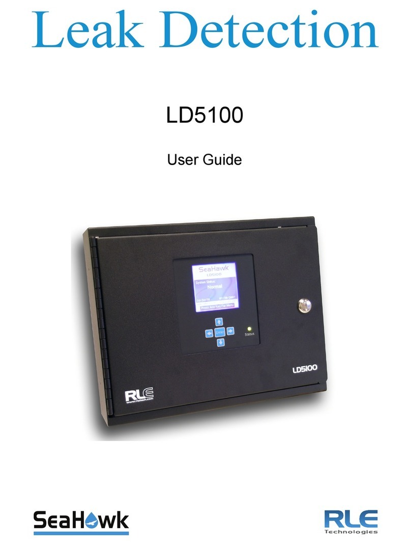
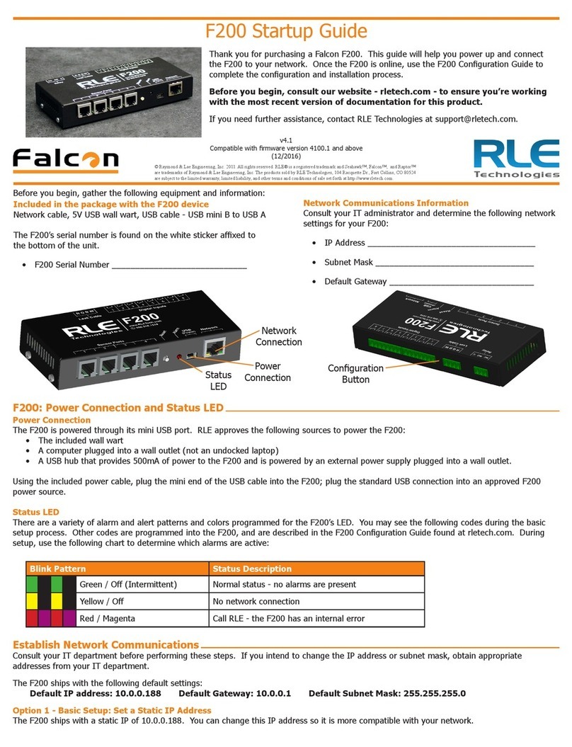
RLE Technologies Falcon FMS User manual

Monitoring
User Guide
FMS
Facilities Monitoring System
Version 1.6
Firmware Version 8.6.16

2 FMS User Guide 800.518.1519
Copyright and Trademark Notices
© Raymond & Lae Engineering, Inc. 2011. All rights reserved. RLE® is a registered trademark and
Seahawk™, Falcon™, and Raptor™ are trademarks of Raymond & Lae Engineering, Inc. The
products sold by Raymond & Lae Engineering, Inc. are subject to the limited warranty, limited liability,
and other terms and conditions of sale set forth at http://rletech.com/RLE-Terms-and-Conditions.html.
Revision History
Rev. No. Date
1.0 June 2010
1.1 September 2010
1.2 November 2010
1.3 March 2011
1.4 August 2011
1.5 November 2011
1.6 May 2012

rletech.com FMS User Guide 3
Product Registration
Product registration helps RLE Technologies inform owners of:
• Product upgrades
• Firmware enhancements
• New products and technologies
• Special offers available only to registered users
Access and submit Product Registration information from the FMS Configuration Menu.
Any information provided to RLE Technologies through the registration form will be regarded as
confidential. RLE will not sell or distribute any of the information to third parties. To read our Privacy
Policy, please visit our website: www.rletech.com.
Technical Support
Personal assistance is available Monday through Friday, from 8:00 a.m. to 5:00 p.m. MST.
A request for assistance may be sent to support@rletech.com.
Otherwise, please call us directly at: (970) 484-6510, and press “2” for technical support.
The following information is located on the bottom of each FMS unit. Please have this information
available whenever a technical support call is placed:
Product Model Number
Product Serial Number
Product Manufacture Date

4 FMS User Guide 800.518.1519
RLE Product Warranty
Seller warrants to the Ultimate Purchaser (the purchaser who buys for use and not for resale) that all
products furnished under this order and which are manufactured by Seller will conform to final
specifications, drawings, samples and other written descriptions approved in writing by Seller, and will be
free from defects in materials and workmanship. These warranties shall remain in effect for a period of
twelve (12) months after shipment. If the Seller installs the equipment or supplies technical direction of
installation by contract, said one year shall run from the completion of installation, provided installation is not
unreasonably delayed by Ultimate Purchaser. Parts replaced or repaired in the warranty period shall carry
the unexpired portion of the original warranty. A unit placed with the purchaser on consignment and then
later purchased will be warranted for twelve (12) months from the time the Seller receives notification of the
Purchaser's intent to purchase said consigned item. The foregoing is in its entirety is subject to the provision
that in no case will the total warranty period extend beyond 18 months from date Seller ships equipment
from point of manufacture.
Products are NOT life and safety certified. In no event shall the Seller be liable for loss, damage, or expense
directly or indirectly arising from the use of the units, or from any other cause, except as expressly stated in
this warranty. Seller makes no warranties, express or implied, including any warranty as to merchantability
or fitness for a particular purpose or use. Seller is not liable for and Purchaser waives any right of action it
has or may have against Seller for any consequential or special damages arising out of any breach of
warranty, and for any damages Purchaser may claim for damage to any property or injury or death to any
person arising out of its purchase or the use, operation, or maintenance of the product. Seller will not be
liable for any labor subcontracted or performed by Purchaser for preparation of warranted item for return to
Seller's factory or for preparation work for field repair or replacement. Invoicing of Seller for labor either
performed or subcontracted by Purchaser will not be considered as a liability by the Seller.
The liability of Seller hereunder is limited to replacing or repairing at Seller's factory or on the job site at
Seller's option, any part or parts which have been returned to the Seller and which are defective or do not
conform to such specifications, drawings or other written descriptions; provided that such part or parts are
returned by the Ultimate Purchaser within ninety (90) days after such defect is discovered. The Seller shall
have the sole right to determine if the parts are to be repaired at the job site or whether they are to be
returned to the factory for repair or replacement. All items returned to Seller for repair or replacement must
be sent freight, prepaid to its factory. Purchaser must obtain Seller's Return Goods Authorization prior to
returning items. The above conditions must be met if warranty is to be valid. Seller will not be liable for any
damage done by unauthorized repair work, unauthorized replacement parts, from any misapplication of the
item, or for damage due to accident, abuse, or act of God.
This warranty shall be exclusive of any and all other warranties express or implied and may be modified only
by writing signed by any officer of the Seller. This warranty shall extend to the Ultimate Purchaser but to no
one else. Accessories supplied by Seller but manufactured by others carry any warranty the manufacturers
have made to Seller and which can be passed on to the Ultimate Purchaser.
Seller makes no warranty with respect to whether the products sold hereunder infringe any patent, U.S. or
foreign, and Purchaser represents that any specially ordered products do not infringe any patent. Purchaser
agrees to indemnify and hold Seller harmless from any liability by virtue of any patent claims where
Purchaser has ordered a product conforming to Purchaser's specifications, or conforming to Purchaser's
specific design.
Purchaser has not relied and shall not rely on any oral representation regarding the Product sold hereunder
and any oral representation shall not bind Seller and shall not be part of any warranty.

Contents
rletech.com FMS User Guide 5
1 System Overview . . . . . . . . . . . . . . . . . . . . . . . . . . . . . . . . . . . . . . . . . . . . . . . . . . .15
Product Description. . . . . . . . . . . . . . . . . . . . . . . . . . . . . . . . . . . . . . . . . . . . . . . . . . . . . . . . . . . . . . . . 15
Front Panel Indicators and Controls . . . . . . . . . . . . . . . . . . . . . . . . . . . . . . . . . . . . . . . . . . . . . . . . . . . 16
Terminal Block Designations. . . . . . . . . . . . . . . . . . . . . . . . . . . . . . . . . . . . . . . . . . . . . . . . . . . . . . . . . 17
Rear Panel Indicators . . . . . . . . . . . . . . . . . . . . . . . . . . . . . . . . . . . . . . . . . . . . . . . . . . . . . . . . . . . . . . 19
SW1 Switch Settings. . . . . . . . . . . . . . . . . . . . . . . . . . . . . . . . . . . . . . . . . . . . . . . . . . . . . . . . . . . . . . . 19
2 Getting Started . . . . . . . . . . . . . . . . . . . . . . . . . . . . . . . . . . . . . . . . . . . . . . . . . . . . .21
Installation . . . . . . . . . . . . . . . . . . . . . . . . . . . . . . . . . . . . . . . . . . . . . . . . . . . . . . . . . . . . . . . . . . . . . . . 21
Falcon FMS Wiring . . . . . . . . . . . . . . . . . . . . . . . . . . . . . . . . . . . . . . . . . . . . . . . . . . . . . . . . . . . . . . . . 21
Power Supply and Ground Connections . . . . . . . . . . . . . . . . . . . . . . . . . . . . . . . . . . . . . . . . . . . 21
Universal Input Connections . . . . . . . . . . . . . . . . . . . . . . . . . . . . . . . . . . . . . . . . . . . . . . . . . . . . 22
Relay 1 and 2 Connections . . . . . . . . . . . . . . . . . . . . . . . . . . . . . . . . . . . . . . . . . . . . . . . . . . . . . 24
Keypad Connection . . . . . . . . . . . . . . . . . . . . . . . . . . . . . . . . . . . . . . . . . . . . . . . . . . . . . . . . . . . 25
EIA-232 COM2 Connection . . . . . . . . . . . . . . . . . . . . . . . . . . . . . . . . . . . . . . . . . . . . . . . . . . . . . 25
RJ11 Phone Line Connection . . . . . . . . . . . . . . . . . . . . . . . . . . . . . . . . . . . . . . . . . . . . . . . . . . . 26
RJ45 Ethernet Connection . . . . . . . . . . . . . . . . . . . . . . . . . . . . . . . . . . . . . . . . . . . . . . . . . . . . . . 26
Modbus EIA-485 Connections . . . . . . . . . . . . . . . . . . . . . . . . . . . . . . . . . . . . . . . . . . . . . . . . . . . 27
Modbus EIA-232 Connections . . . . . . . . . . . . . . . . . . . . . . . . . . . . . . . . . . . . . . . . . . . . . . . . . . . 28
Expansion Card A Connections . . . . . . . . . . . . . . . . . . . . . . . . . . . . . . . . . . . . . . . . . . . . . . . . . . 29
Expansion Card C Connections . . . . . . . . . . . . . . . . . . . . . . . . . . . . . . . . . . . . . . . . . . . . . . . . . . 31
Communication . . . . . . . . . . . . . . . . . . . . . . . . . . . . . . . . . . . . . . . . . . . . . . . . . . . . . . . . . . . . . . . . . . . 32
Set the FMS IP Address. . . . . . . . . . . . . . . . . . . . . . . . . . . . . . . . . . . . . . . . . . . . . . . . . . . . . . . . 32
Set the IP Address Using the ARP and PING Commands . . . . . . . . . . . . . . . . . . . . . . . . . . . . . 32
Obtain the Ethernet Address (MAC Address) . . . . . . . . . . . . . . . . . . . . . . . . . . . . . . . . . . . . 32
Use the ARP Command . . . . . . . . . . . . . . . . . . . . . . . . . . . . . . . . . . . . . . . . . . . . . . . . . . . . 32
Use the PING Command . . . . . . . . . . . . . . . . . . . . . . . . . . . . . . . . . . . . . . . . . . . . . . . . . . . . 33
Troubleshooting the ARP/PING Commands . . . . . . . . . . . . . . . . . . . . . . . . . . . . . . . . . . . . . 33
Set the IP Address Using a Web Browser . . . . . . . . . . . . . . . . . . . . . . . . . . . . . . . . . . . . . . . . . . 33
Set the FMS IP Address using an EIA-232 Connection. . . . . . . . . . . . . . . . . . . . . . . . . . . . . . . . 34
3 FMS Web Interface . . . . . . . . . . . . . . . . . . . . . . . . . . . . . . . . . . . . . . . . . . . . . . . . . .35
Main Menu/ Home Page . . . . . . . . . . . . . . . . . . . . . . . . . . . . . . . . . . . . . . . . . . . . . . . . . . . . . . . . . . . . 35
Identity. . . . . . . . . . . . . . . . . . . . . . . . . . . . . . . . . . . . . . . . . . . . . . . . . . . . . . . . . . . . . . . . . . . . . . . . . . 36
Configuration. . . . . . . . . . . . . . . . . . . . . . . . . . . . . . . . . . . . . . . . . . . . . . . . . . . . . . . . . . . . . . . . . . . . . 37
History . . . . . . . . . . . . . . . . . . . . . . . . . . . . . . . . . . . . . . . . . . . . . . . . . . . . . . . . . . . . . . . . . . . . . . . . . . 38
Alarm History . . . . . . . . . . . . . . . . . . . . . . . . . . . . . . . . . . . . . . . . . . . . . . . . . . . . . . . . . . . . . . . . 38
Event History . . . . . . . . . . . . . . . . . . . . . . . . . . . . . . . . . . . . . . . . . . . . . . . . . . . . . . . . . . . . . . . . 39
Digital Status History . . . . . . . . . . . . . . . . . . . . . . . . . . . . . . . . . . . . . . . . . . . . . . . . . . . . . . . . . . 39
Keypad Access History . . . . . . . . . . . . . . . . . . . . . . . . . . . . . . . . . . . . . . . . . . . . . . . . . . . . . . . . 40
Web Access . . . . . . . . . . . . . . . . . . . . . . . . . . . . . . . . . . . . . . . . . . . . . . . . . . . . . . . . . . . . . . . . . 40
Data . . . . . . . . . . . . . . . . . . . . . . . . . . . . . . . . . . . . . . . . . . . . . . . . . . . . . . . . . . . . . . . . . . . . . . . 41
Minute, Hour, and Day View . . . . . . . . . . . . . . . . . . . . . . . . . . . . . . . . . . . . . . . . . . . . . . . . . 41
Data History Text Downloads . . . . . . . . . . . . . . . . . . . . . . . . . . . . . . . . . . . . . . . . . . . . . . . . 42
Alarm History Text (alarmhistory.txt) . . . . . . . . . . . . . . . . . . . . . . . . . . . . . . . . . . . . . . . . . . . 43
Graph. . . . . . . . . . . . . . . . . . . . . . . . . . . . . . . . . . . . . . . . . . . . . . . . . . . . . . . . . . . . . . . . . . . 43
Trends . . . . . . . . . . . . . . . . . . . . . . . . . . . . . . . . . . . . . . . . . . . . . . . . . . . . . . . . . . . . . . . . . . . . . 45

6 FMS User Guide 800.518.1519
Trap Log . . . . . . . . . . . . . . . . . . . . . . . . . . . . . . . . . . . . . . . . . . . . . . . . . . . . . . . . . . . . . . . . . . . . 46
Relays . . . . . . . . . . . . . . . . . . . . . . . . . . . . . . . . . . . . . . . . . . . . . . . . . . . . . . . . . . . . . . . . . . . . . . . . . . 46
URL Links . . . . . . . . . . . . . . . . . . . . . . . . . . . . . . . . . . . . . . . . . . . . . . . . . . . . . . . . . . . . . . . . . . . . . . . 47
Refresh . . . . . . . . . . . . . . . . . . . . . . . . . . . . . . . . . . . . . . . . . . . . . . . . . . . . . . . . . . . . . . . . . . . . . . . . . 47
4 FMS Configuration . . . . . . . . . . . . . . . . . . . . . . . . . . . . . . . . . . . . . . . . . . . . . . . . . . 49
FMS Web Interface Overview . . . . . . . . . . . . . . . . . . . . . . . . . . . . . . . . . . . . . . . . . . . . . . . . . . . . . . . . 49
Homepage and Configuration Menu . . . . . . . . . . . . . . . . . . . . . . . . . . . . . . . . . . . . . . . . . . . . . . . . . . . 51
Inputs and Relays . . . . . . . . . . . . . . . . . . . . . . . . . . . . . . . . . . . . . . . . . . . . . . . . . . . . . . . . . . . . . . . . . 52
Main Board Input Configuration (Channels 1-8) . . . . . . . . . . . . . . . . . . . . . . . . . . . . . . . . . . . . . . 53
Expansion Card “A” Input Configuration. . . . . . . . . . . . . . . . . . . . . . . . . . . . . . . . . . . . . . . . . . . . 59
Expansion Card “C” Input Configuration. . . . . . . . . . . . . . . . . . . . . . . . . . . . . . . . . . . . . . . . . . . . 60
Internal Temperature and Internal Humidity Configuration (Optional) . . . . . . . . . . . . . . . . . . 60
Relay Configuration . . . . . . . . . . . . . . . . . . . . . . . . . . . . . . . . . . . . . . . . . . . . . . . . . . . . . . . . . . . 61
System. . . . . . . . . . . . . . . . . . . . . . . . . . . . . . . . . . . . . . . . . . . . . . . . . . . . . . . . . . . . . . . . . . . . . . . . . . 63
Alarm Management . . . . . . . . . . . . . . . . . . . . . . . . . . . . . . . . . . . . . . . . . . . . . . . . . . . . . . . . . . . . . . . . 65
Trends . . . . . . . . . . . . . . . . . . . . . . . . . . . . . . . . . . . . . . . . . . . . . . . . . . . . . . . . . . . . . . . . . . . . . . . . . . 66
Clock . . . . . . . . . . . . . . . . . . . . . . . . . . . . . . . . . . . . . . . . . . . . . . . . . . . . . . . . . . . . . . . . . . . . . . . . . . . 67
Schedules . . . . . . . . . . . . . . . . . . . . . . . . . . . . . . . . . . . . . . . . . . . . . . . . . . . . . . . . . . . . . . . . . . . . . . . 67
Battery/Supply Voltage . . . . . . . . . . . . . . . . . . . . . . . . . . . . . . . . . . . . . . . . . . . . . . . . . . . . . . . . . . . . . 68
URL Links (1-5) . . . . . . . . . . . . . . . . . . . . . . . . . . . . . . . . . . . . . . . . . . . . . . . . . . . . . . . . . . . . . . . . . . . 68
URL Links (6-10) . . . . . . . . . . . . . . . . . . . . . . . . . . . . . . . . . . . . . . . . . . . . . . . . . . . . . . . . . . . . . . . . . . 69
Links . . . . . . . . . . . . . . . . . . . . . . . . . . . . . . . . . . . . . . . . . . . . . . . . . . . . . . . . . . . . . . . . . . . . . . . . . . . 69
Nest/Egg . . . . . . . . . . . . . . . . . . . . . . . . . . . . . . . . . . . . . . . . . . . . . . . . . . . . . . . . . . . . . . . . . . . . . . . . 70
Falcon Nest Configuration . . . . . . . . . . . . . . . . . . . . . . . . . . . . . . . . . . . . . . . . . . . . . . . . . . . . . . 70
Egg Configuration. . . . . . . . . . . . . . . . . . . . . . . . . . . . . . . . . . . . . . . . . . . . . . . . . . . . . . . . . . . . . 71
Modem/Phone Numbers/Pagers . . . . . . . . . . . . . . . . . . . . . . . . . . . . . . . . . . . . . . . . . . . . . . . . . . . . . . 72
Configure Phone Numbers . . . . . . . . . . . . . . . . . . . . . . . . . . . . . . . . . . . . . . . . . . . . . . . . . . . . . . 73
Configure Phone Number 16 (PPP) . . . . . . . . . . . . . . . . . . . . . . . . . . . . . . . . . . . . . . . . . . . . . . . 75
Keypad/DTMF Access Users. . . . . . . . . . . . . . . . . . . . . . . . . . . . . . . . . . . . . . . . . . . . . . . . . . . . . . . . . 75
Internet Protocol . . . . . . . . . . . . . . . . . . . . . . . . . . . . . . . . . . . . . . . . . . . . . . . . . . . . . . . . . . . . . . . . . . 76
User Administration (Web Access) . . . . . . . . . . . . . . . . . . . . . . . . . . . . . . . . . . . . . . . . . . . . . . . . . . . . 77
Network Statistics . . . . . . . . . . . . . . . . . . . . . . . . . . . . . . . . . . . . . . . . . . . . . . . . . . . . . . . . . . . . . . . . . 78
ICMP Ping . . . . . . . . . . . . . . . . . . . . . . . . . . . . . . . . . . . . . . . . . . . . . . . . . . . . . . . . . . . . . . . . . . . . . . . 78
Email/DNS . . . . . . . . . . . . . . . . . . . . . . . . . . . . . . . . . . . . . . . . . . . . . . . . . . . . . . . . . . . . . . . . . . . . . . . 79
Network Time Protocol . . . . . . . . . . . . . . . . . . . . . . . . . . . . . . . . . . . . . . . . . . . . . . . . . . . . . . . . . . . . . 80
SNMP/Syslog. . . . . . . . . . . . . . . . . . . . . . . . . . . . . . . . . . . . . . . . . . . . . . . . . . . . . . . . . . . . . . . . . . . . . 81
BACnet . . . . . . . . . . . . . . . . . . . . . . . . . . . . . . . . . . . . . . . . . . . . . . . . . . . . . . . . . . . . . . . . . . . . . . . . . 82
Com Port1/Modbus/SNMP/Telnet . . . . . . . . . . . . . . . . . . . . . . . . . . . . . . . . . . . . . . . . . . . . . . . . . . . . . 83
Modbus/SNMP Slave Units . . . . . . . . . . . . . . . . . . . . . . . . . . . . . . . . . . . . . . . . . . . . . . . . . . . . . . . . . . 84
PUE/DCiE/Summary . . . . . . . . . . . . . . . . . . . . . . . . . . . . . . . . . . . . . . . . . . . . . . . . . . . . . . . . . . . . . . . 85
Map . . . . . . . . . . . . . . . . . . . . . . . . . . . . . . . . . . . . . . . . . . . . . . . . . . . . . . . . . . . . . . . . . . . . . . . . . . . . 85
Flash Program . . . . . . . . . . . . . . . . . . . . . . . . . . . . . . . . . . . . . . . . . . . . . . . . . . . . . . . . . . . . . . . . . . . . 86
Product Registration . . . . . . . . . . . . . . . . . . . . . . . . . . . . . . . . . . . . . . . . . . . . . . . . . . . . . . . . . . . . . . . 86
5 Communication . . . . . . . . . . . . . . . . . . . . . . . . . . . . . . . . . . . . . . . . . . . . . . . . . . . . 87
Modbus . . . . . . . . . . . . . . . . . . . . . . . . . . . . . . . . . . . . . . . . . . . . . . . . . . . . . . . . . . . . . . . . . . . . . . . . . 87
Hardware Connections . . . . . . . . . . . . . . . . . . . . . . . . . . . . . . . . . . . . . . . . . . . . . . . . . . . . . . . . . . . . . 87
EIA-232. . . . . . . . . . . . . . . . . . . . . . . . . . . . . . . . . . . . . . . . . . . . . . . . . . . . . . . . . . . . . . . . . . . . . 87
EIA-485. . . . . . . . . . . . . . . . . . . . . . . . . . . . . . . . . . . . . . . . . . . . . . . . . . . . . . . . . . . . . . . . . . . . . 89
Modbus/SNMP/COM1 Configuration (Modbus Master and Slave) . . . . . . . . . . . . . . . . . . . . . . . . . . . . 91
Modbus Slave Register Display Log. . . . . . . . . . . . . . . . . . . . . . . . . . . . . . . . . . . . . . . . . . . . . . . 93
Modbus Packet Log . . . . . . . . . . . . . . . . . . . . . . . . . . . . . . . . . . . . . . . . . . . . . . . . . . . . . . . . . . . 95
Reset Modbus Port. . . . . . . . . . . . . . . . . . . . . . . . . . . . . . . . . . . . . . . . . . . . . . . . . . . . . . . . . . . . 95
Modbus Master Poll Data Log . . . . . . . . . . . . . . . . . . . . . . . . . . . . . . . . . . . . . . . . . . . . . . . . . . . 96
SMS/Text Modem Log . . . . . . . . . . . . . . . . . . . . . . . . . . . . . . . . . . . . . . . . . . . . . . . . . . . . . . . . . 96

rletech.com FMS User Guide 7
Configuring Inputs and Relays for Slave Units (Modbus, SNMP, or BACnet) . . . . . . . . . . . . . . . . . . . 97
Modbus/SNMP Slave Units Configuration—Modbus Generic (Typical) . . . . . . . . . . . . . . . . . . . . . . . 100
Unit Number Links . . . . . . . . . . . . . . . . . . . . . . . . . . . . . . . . . . . . . . . . . . . . . . . . . . . . . . . . . . . 101
Modbus Register Links. . . . . . . . . . . . . . . . . . . . . . . . . . . . . . . . . . . . . . . . . . . . . . . . . . . . . . . . 103
Read/Preset Single Register . . . . . . . . . . . . . . . . . . . . . . . . . . . . . . . . . . . . . . . . . . . . . . . . . . . 105
Modbus/Slave Units Configuration – Modbus Master BCM – 4 . . . . . . . . . . . . . . . . . . . . . . . . . . . . . 105
Unit Number Links . . . . . . . . . . . . . . . . . . . . . . . . . . . . . . . . . . . . . . . . . . . . . . . . . . . . . . . . . . . 107
Modbus Register Links. . . . . . . . . . . . . . . . . . . . . . . . . . . . . . . . . . . . . . . . . . . . . . . . . . . . . . . . 108
CB# Links . . . . . . . . . . . . . . . . . . . . . . . . . . . . . . . . . . . . . . . . . . . . . . . . . . . . . . . . . . . . . . 109
Modbus/Slave Units Configuration – Modbus Master BCM – 16 . . . . . . . . . . . . . . . . . . . . . . . . . . . . 110
Additional Modbus Information . . . . . . . . . . . . . . . . . . . . . . . . . . . . . . . . . . . . . . . . . . . . . . . . . . . . . . 111
Slave Register Map . . . . . . . . . . . . . . . . . . . . . . . . . . . . . . . . . . . . . . . . . . . . . . . . . . . . . . . . . . 111
Alarm Bit Map (Reg 40201–-40306) . . . . . . . . . . . . . . . . . . . . . . . . . . . . . . . . . . . . . . . . . . . . . 112
Configuration Codes (Reg 40401–40504) . . . . . . . . . . . . . . . . . . . . . . . . . . . . . . . . . . . . . . . . . 112
BACnet Slave Units Configuration – BACnet/IP Master . . . . . . . . . . . . . . . . . . . . . . . . . . . . . . . . . . . 113
BACnet Configuration . . . . . . . . . . . . . . . . . . . . . . . . . . . . . . . . . . . . . . . . . . . . . . . . . . . . . . . . 114
BACnet Slave Unit Configuration . . . . . . . . . . . . . . . . . . . . . . . . . . . . . . . . . . . . . . . . . . . . . . . . 115
Unit Number Links . . . . . . . . . . . . . . . . . . . . . . . . . . . . . . . . . . . . . . . . . . . . . . . . . . . . . . . . . . . 116
BACnet Instance Register Links . . . . . . . . . . . . . . . . . . . . . . . . . . . . . . . . . . . . . . . . . . . . . . . . 117
Telnet . . . . . . . . . . . . . . . . . . . . . . . . . . . . . . . . . . . . . . . . . . . . . . . . . . . . . . . . . . . . . . . . . . . . . . . . . 117
Hardware Connections. . . . . . . . . . . . . . . . . . . . . . . . . . . . . . . . . . . . . . . . . . . . . . . . . . . . . . . . 117
Telnet/COM1 Configuration . . . . . . . . . . . . . . . . . . . . . . . . . . . . . . . . . . . . . . . . . . . . . . . . . . . . 119
Telnet Communication . . . . . . . . . . . . . . . . . . . . . . . . . . . . . . . . . . . . . . . . . . . . . . . . . . . . . . . . 119
6 PUE/DCiE . . . . . . . . . . . . . . . . . . . . . . . . . . . . . . . . . . . . . . . . . . . . . . . . . . . . . . . . .121
Facility Power Monitoring . . . . . . . . . . . . . . . . . . . . . . . . . . . . . . . . . . . . . . . . . . . . . . . . . . . . . . . . . . 121
Designating PUE/DCiE Data. . . . . . . . . . . . . . . . . . . . . . . . . . . . . . . . . . . . . . . . . . . . . . . . . . . . . . . . 122
PUE/DCiE Trending . . . . . . . . . . . . . . . . . . . . . . . . . . . . . . . . . . . . . . . . . . . . . . . . . . . . . . . . . . . . . . 124
Format Trends . . . . . . . . . . . . . . . . . . . . . . . . . . . . . . . . . . . . . . . . . . . . . . . . . . . . . . . . . . . . . . 124
View Trends . . . . . . . . . . . . . . . . . . . . . . . . . . . . . . . . . . . . . . . . . . . . . . . . . . . . . . . . . . . . . . . . 125
7 Facility Mapping . . . . . . . . . . . . . . . . . . . . . . . . . . . . . . . . . . . . . . . . . . . . . . . . . . .127
FMS Mapping Feature . . . . . . . . . . . . . . . . . . . . . . . . . . . . . . . . . . . . . . . . . . . . . . . . . . . . . . . . . . . . 127
Upload the Map Image . . . . . . . . . . . . . . . . . . . . . . . . . . . . . . . . . . . . . . . . . . . . . . . . . . . . . . . . . . . . 128
Map Inputs . . . . . . . . . . . . . . . . . . . . . . . . . . . . . . . . . . . . . . . . . . . . . . . . . . . . . . . . . . . . . . . . . . . . . 129
Map Analog and Digital Input Points . . . . . . . . . . . . . . . . . . . . . . . . . . . . . . . . . . . . . . . . . . . . . 130
Map Modbus and SMNP Slave Units. . . . . . . . . . . . . . . . . . . . . . . . . . . . . . . . . . . . . . . . . . . . . 131
Add a Link to the FMS Home Page . . . . . . . . . . . . . . . . . . . . . . . . . . . . . . . . . . . . . . . . . . . . . . 133
Back Up the Map Data . . . . . . . . . . . . . . . . . . . . . . . . . . . . . . . . . . . . . . . . . . . . . . . . . . . . . . . . . . . . 133
8 EIA-232 Interface . . . . . . . . . . . . . . . . . . . . . . . . . . . . . . . . . . . . . . . . . . . . . . . . . . .135
Unit Start Up . . . . . . . . . . . . . . . . . . . . . . . . . . . . . . . . . . . . . . . . . . . . . . . . . . . . . . . . . . . . . . . . . . . . 135
Flash Executable Code . . . . . . . . . . . . . . . . . . . . . . . . . . . . . . . . . . . . . . . . . . . . . . . . . . . . . . . . . . . . 136
Main Menu . . . . . . . . . . . . . . . . . . . . . . . . . . . . . . . . . . . . . . . . . . . . . . . . . . . . . . . . . . . . . . . . . . . . . 136
Network Configuration – netcfg . . . . . . . . . . . . . . . . . . . . . . . . . . . . . . . . . . . . . . . . . . . . . . . . . 137
Bootloader Menu . . . . . . . . . . . . . . . . . . . . . . . . . . . . . . . . . . . . . . . . . . . . . . . . . . . . . . . . . 137
9 Remote Access . . . . . . . . . . . . . . . . . . . . . . . . . . . . . . . . . . . . . . . . . . . . . . . . . . . .139
Remote Access Configuration. . . . . . . . . . . . . . . . . . . . . . . . . . . . . . . . . . . . . . . . . . . . . . . . . . . . . . . 139
10 Point-to-Point Protocol. . . . . . . . . . . . . . . . . . . . . . . . . . . . . . . . . . . . . . . . . . . . . .141
Configuring the FMS . . . . . . . . . . . . . . . . . . . . . . . . . . . . . . . . . . . . . . . . . . . . . . . . . . . . . . . . . . . . . . 141
Configuring the PC . . . . . . . . . . . . . . . . . . . . . . . . . . . . . . . . . . . . . . . . . . . . . . . . . . . . . . . . . . . . . . . 142
11 Loading Firmware and Configuration Data. . . . . . . . . . . . . . . . . . . . . . . . . . . . . .143
Loading FMS Firmware. . . . . . . . . . . . . . . . . . . . . . . . . . . . . . . . . . . . . . . . . . . . . . . . . . . . . . . . . . . . 143
Loading Firmware Using TFTP Client . . . . . . . . . . . . . . . . . . . . . . . . . . . . . . . . . . . . . . . . . . . . 146

8 FMS User Guide 800.518.1519
Updating FMS Firmware via the EIA-232 COM2 Port (X-Modem) . . . . . . . . . . . . . . . . . . . . . . . 146
Loading and Saving FMS Configuration Data . . . . . . . . . . . . . . . . . . . . . . . . . . . . . . . . . . . . . . . . . . . 147
Saving Configuration Data . . . . . . . . . . . . . . . . . . . . . . . . . . . . . . . . . . . . . . . . . . . . . . . . . . . . . 147
Loading Configuration Data . . . . . . . . . . . . . . . . . . . . . . . . . . . . . . . . . . . . . . . . . . . . . . . . . . . . 148
A FMS Expansion Cards . . . . . . . . . . . . . . . . . . . . . . . . . . . . . . . . . . . . . . . . . . . . . . 151
K-1 Expansion Card Descriptions . . . . . . . . . . . . . . . . . . . . . . . . . . . . . . . . . . . . . . . . . . . . . . . . . . . . 151
Expansion Card Installation. . . . . . . . . . . . . . . . . . . . . . . . . . . . . . . . . . . . . . . . . . . . . . . . . . . . . . . . . 152
Installing an Expansion Card into a 2U FMS . . . . . . . . . . . . . . . . . . . . . . . . . . . . . . . . . . . . . . . 152
Installing an Expansion Card into a 1U FMS . . . . . . . . . . . . . . . . . . . . . . . . . . . . . . . . . . . . . . . 158
Converting Current Input Channels to Voltage Input Channels on Expansion Card A . . . . . . . . . . . . 159
B Analog Averaging. . . . . . . . . . . . . . . . . . . . . . . . . . . . . . . . . . . . . . . . . . . . . . . . . . 161
Analog Averaging Overview . . . . . . . . . . . . . . . . . . . . . . . . . . . . . . . . . . . . . . . . . . . . . . . . . . . . . . . . 161
How Analog Averaging Affects Values . . . . . . . . . . . . . . . . . . . . . . . . . . . . . . . . . . . . . . . . . . . . . . . . 161
C Analog Input 4-20mA Reference Chart. . . . . . . . . . . . . . . . . . . . . . . . . . . . . . . . . 163
D FMS Accessories Wiring . . . . . . . . . . . . . . . . . . . . . . . . . . . . . . . . . . . . . . . . . . . . 165
Configuring the SeaHawk LD5100 as an Analog Input . . . . . . . . . . . . . . . . . . . . . . . . . . . . . . . . . . . . 169
Wiring for Other Falcon FMS Accessories. . . . . . . . . . . . . . . . . . . . . . . . . . . . . . . . . . . . . . . . . . . . . . 170
E Alarm ID Reference Tables . . . . . . . . . . . . . . . . . . . . . . . . . . . . . . . . . . . . . . . . . . 171
Analog Tables . . . . . . . . . . . . . . . . . . . . . . . . . . . . . . . . . . . . . . . . . . . . . . . . . . . . . . . . . . . . . . . . . . . 171
Digital Tables. . . . . . . . . . . . . . . . . . . . . . . . . . . . . . . . . . . . . . . . . . . . . . . . . . . . . . . . . . . . . . . . . . . . 175
F FMS Slot Designations. . . . . . . . . . . . . . . . . . . . . . . . . . . . . . . . . . . . . . . . . . . . . . 179
Input Slot Designation Table . . . . . . . . . . . . . . . . . . . . . . . . . . . . . . . . . . . . . . . . . . . . . . . . . . . . . . . . 179
Output Slot Designation Table. . . . . . . . . . . . . . . . . . . . . . . . . . . . . . . . . . . . . . . . . . . . . . . . . . . . . . . 183
G Relay Control Logic . . . . . . . . . . . . . . . . . . . . . . . . . . . . . . . . . . . . . . . . . . . . . . . . 185
Falcon-EM Relay Logic . . . . . . . . . . . . . . . . . . . . . . . . . . . . . . . . . . . . . . . . . . . . . . . . . . . . . . . . . . . . 185
H SNMP v3 . . . . . . . . . . . . . . . . . . . . . . . . . . . . . . . . . . . . . . . . . . . . . . . . . . . . . . . . . 189
I Technical Specifications . . . . . . . . . . . . . . . . . . . . . . . . . . . . . . . . . . . . . . . . . . . . 193

Figures
rletech.com FMS User Guide 9
1 System Overview . . . . . . . . . . . . . . . . . . . . . . . . . . . . . . . . . . . . . . . . . . . . . . . . . . .15
Figure 1.1 FMS 2U Front Panel Indicators and Controls . . . . . . . . . . . . . . . . . . . . . . . . . . 16
Figure 1.2 FMS Terminal Block Designations . . . . . . . . . . . . . . . . . . . . . . . . . . . . . . . . . . 17
Figure 1.3 Rear Panel Indicators . . . . . . . . . . . . . . . . . . . . . . . . . . . . . . . . . . . . . . . . . . . . 19
Figure 1.4 SW1-1 Switch and SW1-2 Switch . . . . . . . . . . . . . . . . . . . . . . . . . . . . . . . . . . . 19
2 Getting Started . . . . . . . . . . . . . . . . . . . . . . . . . . . . . . . . . . . . . . . . . . . . . . . . . . . . .21
Figure 2.1 24VDC Power Supply Connection . . . . . . . . . . . . . . . . . . . . . . . . . . . . . . . . . . 22
Figure 2.2 48VDC Power Supply Connection . . . . . . . . . . . . . . . . . . . . . . . . . . . . . . . . . . 22
Figure 2.3 Universal Input Wiring Examples . . . . . . . . . . . . . . . . . . . . . . . . . . . . . . . . . . . 23
Figure 2.4 Dry Contact Inputs with Common Ground. . . . . . . . . . . . . . . . . . . . . . . . . . . . . 23
Figure 2.5 Relay Output Wiring Examples . . . . . . . . . . . . . . . . . . . . . . . . . . . . . . . . . . . . . 24
Figure 2.6 Keypad Wiring. . . . . . . . . . . . . . . . . . . . . . . . . . . . . . . . . . . . . . . . . . . . . . . . . . 25
Figure 2.7 EIA-232 COM2 Connection. . . . . . . . . . . . . . . . . . . . . . . . . . . . . . . . . . . . . . . . 25
Figure 2.8 FMS Ethernet Connection to a PC using a Crossover Cable . . . . . . . . . . . . . . 26
Figure 2.9 FMS Ethernet Connection to a PC on a Subnet . . . . . . . . . . . . . . . . . . . . . . . . 26
Figure 2.10 FMS EIA-485 Connection . . . . . . . . . . . . . . . . . . . . . . . . . . . . . . . . . . . . . . . . . 27
Figure 2.11 FMS EIA-232 Connection to a DCE or DTE Device . . . . . . . . . . . . . . . . . . . . . 28
Figure 2.12 I/O Terminals for Expansion Card A . . . . . . . . . . . . . . . . . . . . . . . . . . . . . . . . . 29
Figure 2.13 Analog Input Wiring for Expansion Card A . . . . . . . . . . . . . . . . . . . . . . . . . . . . 29
Figure 2.14 Dry Contact Inputs with Ground and Relay Outputs, Expansion Card A . . . . . 30
Figure 2.15 I/O Terminals for Expansion Card C . . . . . . . . . . . . . . . . . . . . . . . . . . . . . . . . . 31
Figure 2.16 Typical Wiring for Expansion Card C . . . . . . . . . . . . . . . . . . . . . . . . . . . . . . . . 31
3 FMS Web Interface . . . . . . . . . . . . . . . . . . . . . . . . . . . . . . . . . . . . . . . . . . . . . . . . . .35
Figure 3.1 Example of a Configured FMS . . . . . . . . . . . . . . . . . . . . . . . . . . . . . . . . . . . . . 35
Figure 3.2 Identity Menu. . . . . . . . . . . . . . . . . . . . . . . . . . . . . . . . . . . . . . . . . . . . . . . . . . . 36
Figure 3.3 Configuration Page . . . . . . . . . . . . . . . . . . . . . . . . . . . . . . . . . . . . . . . . . . . . . . 37
Figure 3.4 Alarm History Page . . . . . . . . . . . . . . . . . . . . . . . . . . . . . . . . . . . . . . . . . . . . . . 38
Figure 3.5 Event History Page . . . . . . . . . . . . . . . . . . . . . . . . . . . . . . . . . . . . . . . . . . . . . . 39
Figure 3.6 Digital Status History Page . . . . . . . . . . . . . . . . . . . . . . . . . . . . . . . . . . . . . . . . 39
Figure 3.7 Keypad Access History View. . . . . . . . . . . . . . . . . . . . . . . . . . . . . . . . . . . . . . . 40
Figure 3.8 Web User Access Log. . . . . . . . . . . . . . . . . . . . . . . . . . . . . . . . . . . . . . . . . . . . 40
Figure 3.9 Data History Page . . . . . . . . . . . . . . . . . . . . . . . . . . . . . . . . . . . . . . . . . . . . . . . 41
Figure 3.10 Minute Page . . . . . . . . . . . . . . . . . . . . . . . . . . . . . . . . . . . . . . . . . . . . . . . . . . . 42
Figure 3.11 Data History Text Downloads Window . . . . . . . . . . . . . . . . . . . . . . . . . . . . . . . 42
Figure 3.12 Alarm History Text Page . . . . . . . . . . . . . . . . . . . . . . . . . . . . . . . . . . . . . . . . . . 43
Figure 3.13 FMS Graph . . . . . . . . . . . . . . . . . . . . . . . . . . . . . . . . . . . . . . . . . . . . . . . . . . . . 43
Figure 3.14 Java Loading Image . . . . . . . . . . . . . . . . . . . . . . . . . . . . . . . . . . . . . . . . . . . . . 44
Figure 3.15 Extended Trends Page . . . . . . . . . . . . . . . . . . . . . . . . . . . . . . . . . . . . . . . . . . . 45
Figure 3.16 Example Trap Log. . . . . . . . . . . . . . . . . . . . . . . . . . . . . . . . . . . . . . . . . . . . . . . 46
Figure 3.17 Example Relay Status Page . . . . . . . . . . . . . . . . . . . . . . . . . . . . . . . . . . . . . . . 46
Figure 3.18 Example Still Images from IP Cameras. . . . . . . . . . . . . . . . . . . . . . . . . . . . . . . 47

10 FMS User Guide 800.518.1519
4 FMS Configuration . . . . . . . . . . . . . . . . . . . . . . . . . . . . . . . . . . . . . . . . . . . . . . . . . 49
Figure 4.1 Initial Login for the FMS . . . . . . . . . . . . . . . . . . . . . . . . . . . . . . . . . . . . . . . . . . 50
Figure 4.2 Top Bar on the FMS Home Page . . . . . . . . . . . . . . . . . . . . . . . . . . . . . . . . . . . 51
Figure 4.3 FMS Configuration Menu . . . . . . . . . . . . . . . . . . . . . . . . . . . . . . . . . . . . . . . . . 51
Figure 4.4 FMS Input/Output Configuration Menu . . . . . . . . . . . . . . . . . . . . . . . . . . . . . . 52
Figure 4.5 FMS Main Board Input Configuration. . . . . . . . . . . . . . . . . . . . . . . . . . . . . . . . 53
Figure 4.6 Gain and Offset Calculator . . . . . . . . . . . . . . . . . . . . . . . . . . . . . . . . . . . . . . . . 54
Figure 4.7 NOI/NC Wiring Example . . . . . . . . . . . . . . . . . . . . . . . . . . . . . . . . . . . . . . . . . . 57
Figure 4.8 Expansion Card “A” Configuration Page . . . . . . . . . . . . . . . . . . . . . . . . . . . . . . 59
Figure 4.9 Expansion Card “C” Configuration Page. . . . . . . . . . . . . . . . . . . . . . . . . . . . . . 60
Figure 4.10 Relay Configuration Page . . . . . . . . . . . . . . . . . . . . . . . . . . . . . . . . . . . . . . . . 61
Figure 4.11 Keypad/Relay Configuration . . . . . . . . . . . . . . . . . . . . . . . . . . . . . . . . . . . . . . 62
Figure 4.12 System Configuration Page . . . . . . . . . . . . . . . . . . . . . . . . . . . . . . . . . . . . . . . 63
Figure 4.13 PDA Width Configuration . . . . . . . . . . . . . . . . . . . . . . . . . . . . . . . . . . . . . . . . . 64
Figure 4.14 Alarm Settings Menu . . . . . . . . . . . . . . . . . . . . . . . . . . . . . . . . . . . . . . . . . . . . 65
Figure 4.15 Trends Configuration Page . . . . . . . . . . . . . . . . . . . . . . . . . . . . . . . . . . . . . . . 66
Figure 4.16 Trend Interval Chart . . . . . . . . . . . . . . . . . . . . . . . . . . . . . . . . . . . . . . . . . . . . . 66
Figure 4.17 Clock Configuration . . . . . . . . . . . . . . . . . . . . . . . . . . . . . . . . . . . . . . . . . . . . . 67
Figure 4.18 Schedule Configuration . . . . . . . . . . . . . . . . . . . . . . . . . . . . . . . . . . . . . . . . . . 67
Figure 4.19 Battery Page . . . . . . . . . . . . . . . . . . . . . . . . . . . . . . . . . . . . . . . . . . . . . . . . . . 68
Figure 4.20 URL (1-5) Links Configuration . . . . . . . . . . . . . . . . . . . . . . . . . . . . . . . . . . . . . 68
Figure 4.21 URL (6-10) Links Configuration . . . . . . . . . . . . . . . . . . . . . . . . . . . . . . . . . . . . 69
Figure 4.22 Links Configuration Page . . . . . . . . . . . . . . . . . . . . . . . . . . . . . . . . . . . . . . . . . 69
Figure 4.23 Nest/Egg Configuration Page. . . . . . . . . . . . . . . . . . . . . . . . . . . . . . . . . . . . . . 70
Figure 4.24 Nest Configuration . . . . . . . . . . . . . . . . . . . . . . . . . . . . . . . . . . . . . . . . . . . . . . 70
Figure 4.25 Egg Configuration . . . . . . . . . . . . . . . . . . . . . . . . . . . . . . . . . . . . . . . . . . . . . . 71
Figure 4.26 Modem Configuration. . . . . . . . . . . . . . . . . . . . . . . . . . . . . . . . . . . . . . . . . . . . 72
Figure 4.27 Phone Number Configuration. . . . . . . . . . . . . . . . . . . . . . . . . . . . . . . . . . . . . . 73
Figure 4.28 Phone Number 16 (PPP) Configuration . . . . . . . . . . . . . . . . . . . . . . . . . . . . . . 75
Figure 4.29 Sample URL (6-10) Links Configuration . . . . . . . . . . . . . . . . . . . . . . . . . . . . . . 75
Figure 4.30 Sample IP Configuration Menu . . . . . . . . . . . . . . . . . . . . . . . . . . . . . . . . . . . . . 76
Figure 4.31 Web Access Configuration. . . . . . . . . . . . . . . . . . . . . . . . . . . . . . . . . . . . . . . . 77
Figure 4.32 Network Statistics Page . . . . . . . . . . . . . . . . . . . . . . . . . . . . . . . . . . . . . . . . . . 78
Figure 4.33 ICMP Ping Page. . . . . . . . . . . . . . . . . . . . . . . . . . . . . . . . . . . . . . . . . . . . . . . . 78
Figure 4.34 Email/DNS Configuration Page. . . . . . . . . . . . . . . . . . . . . . . . . . . . . . . . . . . . . 79
Figure 4.35 Network Time Protocol Configuration Page. . . . . . . . . . . . . . . . . . . . . . . . . . . 80
Figure 4.36 SNMP Configuration Page . . . . . . . . . . . . . . . . . . . . . . . . . . . . . . . . . . . . . . . . 81
Figure 4.37 BACnet Configuration Pages . . . . . . . . . . . . . . . . . . . . . . . . . . . . . . . . . . . . . . 82
Figure 4.38 Com Port1/Modbus/SNMP/Telnet Configuration . . . . . . . . . . . . . . . . . . . . . . . 83
Figure 4.39 Modbus Generic Slave Unit Configuration . . . . . . . . . . . . . . . . . . . . . . . . . . . . 84
Figure 4.40 Modbus BCM 16-Unit Configuration Page . . . . . . . . . . . . . . . . . . . . . . . . . . . . 84
Figure 4.41 Modbus BCM 4-Unit Configuration Page . . . . . . . . . . . . . . . . . . . . . . . . . . . . . 85
Figure 4.42 Flash Program Configuration Page. . . . . . . . . . . . . . . . . . . . . . . . . . . . . . . . . . 86
5 Communication . . . . . . . . . . . . . . . . . . . . . . . . . . . . . . . . . . . . . . . . . . . . . . . . . . . . 87
Figure 5.1 FMS Modbus EIA-232 Connection to an EIA-232 DCE Device . . . . . . . . . . . . 88
Figure 5.2 FMS Modbus EIA-232 Connection to an EIA-232 DTE Device . . . . . . . . . . . . 88
Figure 5.3 EIA-485 Wiring Connections . . . . . . . . . . . . . . . . . . . . . . . . . . . . . . . . . . . . . . . 89
Figure 5.4 EIA-485 Wiring to RLE/Veris BCMs (Branch Circuit Monitors) . . . . . . . . . . . . . 90
Figure 5.5 Example Modbus/SNMP/COM1 Configuration—Modbus Master. . . . . . . . . . . 91
Figure 5.6 Modbus Slave Register Display Log . . . . . . . . . . . . . . . . . . . . . . . . . . . . . . . . . 93

rletech.com FMS User Guide 11
Figure 5.7 Modbus Packet Log . . . . . . . . . . . . . . . . . . . . . . . . . . . . . . . . . . . . . . . . . . . . . 95
Figure 5.8 Modbus Rest Port Confirmation . . . . . . . . . . . . . . . . . . . . . . . . . . . . . . . . . . . . 95
Figure 5.9 Example Modbus Master Poll Data Log . . . . . . . . . . . . . . . . . . . . . . . . . . . . . . 96
Figure 5.10 Input and Relay Configuration Menu. . . . . . . . . . . . . . . . . . . . . . . . . . . . . . . . . 97
Figure 5.11 Individual Input Configuration Screen . . . . . . . . . . . . . . . . . . . . . . . . . . . . . . . . 98
Figure 5.12 Modbus Slave Unit Configuration . . . . . . . . . . . . . . . . . . . . . . . . . . . . . . . . . . 100
Figure 5.13 Example Modbus Slave Unit . . . . . . . . . . . . . . . . . . . . . . . . . . . . . . . . . . . . . . 101
Figure 5.14 Modbus Register Configuration Menu. . . . . . . . . . . . . . . . . . . . . . . . . . . . . . . 103
Figure 5.15 Individual Modbus Configuration Screen. . . . . . . . . . . . . . . . . . . . . . . . . . . . . 103
Figure 5.16 Read/Preset Single Register Page . . . . . . . . . . . . . . . . . . . . . . . . . . . . . . . . . 105
Figure 5.17 Modbus BCM-4 Unit Configuration . . . . . . . . . . . . . . . . . . . . . . . . . . . . . . . . . 106
Figure 5.18 Individual Slave Configuration Screen . . . . . . . . . . . . . . . . . . . . . . . . . . . . . . 107
Figure 5.19 Modbus Registers (BCM) Page. . . . . . . . . . . . . . . . . . . . . . . . . . . . . . . . . . . . 108
Figure 5.20 Circuit Breaker Configurations for Individual BCMs . . . . . . . . . . . . . . . . . . . . 109
Figure 5.21 Modbus BCM-16 Unit Configuration Page . . . . . . . . . . . . . . . . . . . . . . . . . . . 110
Figure 5.22 BACnet Configuration Page . . . . . . . . . . . . . . . . . . . . . . . . . . . . . . . . . . . . . . 114
Figure 5.23 BACnet Unit Configuration . . . . . . . . . . . . . . . . . . . . . . . . . . . . . . . . . . . . . . . 115
Figure 5.24 Individual Slave Unit Configuration Page . . . . . . . . . . . . . . . . . . . . . . . . . . . . 116
Figure 5.25 BACnet Instance Configuration. . . . . . . . . . . . . . . . . . . . . . . . . . . . . . . . . . . . 116
Figure 5.26 BACnet Configuration Registers Page . . . . . . . . . . . . . . . . . . . . . . . . . . . . . . 117
Figure 5.27 FMS Connection to an EIA-232 Device. . . . . . . . . . . . . . . . . . . . . . . . . . . . . . 118
Figure 5.28 COM Port1/Modbus/SNMP/Telnet Configuration Page . . . . . . . . . . . . . . . . . 119
Figure 5.29 Telnet Communication, IP Address of 10.0.0.108, Port 3201 . . . . . . . . . . . . . 120
Figure 5.30 Example Telnet Connection Showing Specific Parameters . . . . . . . . . . . . . . 120
6 PUE/DCiE . . . . . . . . . . . . . . . . . . . . . . . . . . . . . . . . . . . . . . . . . . . . . . . . . . . . . . . .121
Figure 6.1 PUE/DCiE Data on FMS Home Page . . . . . . . . . . . . . . . . . . . . . . . . . . . . . . . 121
Figure 6.2 Gather Modbus Register Information . . . . . . . . . . . . . . . . . . . . . . . . . . . . . . . 122
Figure 6.3 Enable PUE/DCiE and Designate Gauge Behavior . . . . . . . . . . . . . . . . . . . . 123
Figure 6.4 Designate kW Gathering Devices . . . . . . . . . . . . . . . . . . . . . . . . . . . . . . . . . . 123
Figure 6.5 Data for Third Party Applications. . . . . . . . . . . . . . . . . . . . . . . . . . . . . . . . . . . 124
Figure 6.6 Establish Trending . . . . . . . . . . . . . . . . . . . . . . . . . . . . . . . . . . . . . . . . . . . . . 125
Figure 6.7 View your Trending Data. . . . . . . . . . . . . . . . . . . . . . . . . . . . . . . . . . . . . . . . . 125
Figure 6.8 Trending Graph . . . . . . . . . . . . . . . . . . . . . . . . . . . . . . . . . . . . . . . . . . . . . . . . 125
Figure 6.9 CSV Data . . . . . . . . . . . . . . . . . . . . . . . . . . . . . . . . . . . . . . . . . . . . . . . . . . . . 126
7 Facility Mapping . . . . . . . . . . . . . . . . . . . . . . . . . . . . . . . . . . . . . . . . . . . . . . . . . . .127
Figure 7.1 FMS Map. . . . . . . . . . . . . . . . . . . . . . . . . . . . . . . . . . . . . . . . . . . . . . . . . . . . . 127
Figure 7.2 Map Configuration Page . . . . . . . . . . . . . . . . . . . . . . . . . . . . . . . . . . . . . . . . . 128
Figure 7.3 Map Image Upload Message . . . . . . . . . . . . . . . . . . . . . . . . . . . . . . . . . . . . . 128
Figure 7.4 Map Image Upload Error Message . . . . . . . . . . . . . . . . . . . . . . . . . . . . . . . . . 129
Figure 7.5 FMS Mapping Crosshairs - Insertion Point . . . . . . . . . . . . . . . . . . . . . . . . . . . 129
Figure 7.6 FMS Map Key . . . . . . . . . . . . . . . . . . . . . . . . . . . . . . . . . . . . . . . . . . . . . . . . . 130
Figure 7.7 FMS Input/Output Configuration Menu . . . . . . . . . . . . . . . . . . . . . . . . . . . . . . 130
Figure 7.8 FMS Input Configuration Menu . . . . . . . . . . . . . . . . . . . . . . . . . . . . . . . . . . . . 130
Figure 7.9 FMS Mapping Crosshairs - Insertion Point . . . . . . . . . . . . . . . . . . . . . . . . . . . 131
Figure 7.10 Modbus/SNMP (Slave) Unit Configuration Screen . . . . . . . . . . . . . . . . . . . . . 132
Figure 7.11 Mapping Point Insertion . . . . . . . . . . . . . . . . . . . . . . . . . . . . . . . . . . . . . . . . . 132
Figure 7.12 Modbus / SNMP Slave Unit Detailed View . . . . . . . . . . . . . . . . . . . . . . . . . . . 133
8 EIA-232 Interface . . . . . . . . . . . . . . . . . . . . . . . . . . . . . . . . . . . . . . . . . . . . . . . . . .135
9 Remote Access . . . . . . . . . . . . . . . . . . . . . . . . . . . . . . . . . . . . . . . . . . . . . . . . . . .139

12 FMS User Guide 800.518.1519
Figure 9.1 FMS Dial-Up Menu . . . . . . . . . . . . . . . . . . . . . . . . . . . . . . . . . . . . . . . . . . . . . 140
10 Point-to-Point Protocol . . . . . . . . . . . . . . . . . . . . . . . . . . . . . . . . . . . . . . . . . . . . . 141
11 Loading Firmware and Configuration Data . . . . . . . . . . . . . . . . . . . . . . . . . . . . . 143
Figure 11.1 Flash Program Configuration Page. . . . . . . . . . . . . . . . . . . . . . . . . . . . . . . . . 144
Figure 11.2 Choosing a Firmware File . . . . . . . . . . . . . . . . . . . . . . . . . . . . . . . . . . . . . . . . 144
Figure 11.3 Firmware Load Messages. . . . . . . . . . . . . . . . . . . . . . . . . . . . . . . . . . . . . . . . 145
Figure 11.4 Current Firmware Version As Shown in FMS Interface . . . . . . . . . . . . . . . . . 145
Figure 11.5 Save Configuration File (Flash Program Configuration Page) . . . . . . . . . . . . 147
Figure 11.6 Load Configuration File (Flash Program Configuration Page) . . . . . . . . . . . . 148
A FMS Expansion Cards . . . . . . . . . . . . . . . . . . . . . . . . . . . . . . . . . . . . . . . . . . . . . . 151
Figure A.1 Back of 2U FMS Showing Hex Standoffs and Screws to Remove . . . . . . . . 152
Figure A.2 Side Plate (“Ear”) with Two Mounting Screws Removed . . . . . . . . . . . . . . . . 152
Figure A.3 Sliding the Base and Cover Apart . . . . . . . . . . . . . . . . . . . . . . . . . . . . . . . . . 153
Figure A.4 Two-Rack Unit Opened . . . . . . . . . . . . . . . . . . . . . . . . . . . . . . . . . . . . . . . . . 153
Figure A.5 SW2 DIP Switches . . . . . . . . . . . . . . . . . . . . . . . . . . . . . . . . . . . . . . . . . . . . . 154
Figure A.6 Expansion Card with Ribbon Cable Attached . . . . . . . . . . . . . . . . . . . . . . . . 155
Figure A.7 Expansion Card Mounting in a Two-Rack Unit . . . . . . . . . . . . . . . . . . . . . . . 156
Figure A.8 Expansion Card Final Placement in a Two-Rack Unit . . . . . . . . . . . . . . . . . . 157
Figure A.9 Expansion Card Current Channel (4-20mA) Configuration . . . . . . . . . . . . . . 159
Figure A.10 Expansion Card Voltage Channel (0-5V or 0-10V) Configuration . . . . . . . . . 159
B Analog Averaging . . . . . . . . . . . . . . . . . . . . . . . . . . . . . . . . . . . . . . . . . . . . . . . . . 161
C Analog Input 4-20mA Reference Chart . . . . . . . . . . . . . . . . . . . . . . . . . . . . . . . . 163
D FMS Accessories Wiring . . . . . . . . . . . . . . . . . . . . . . . . . . . . . . . . . . . . . . . . . . . . 165
Figure D.1 T120 and T120D Temperature Sensors . . . . . . . . . . . . . . . . . . . . . . . . . . . . 165
Figure D.2 TH140 and TH140D Temperature/Humidity Sensors . . . . . . . . . . . . . . . . . . 165
Figure D.3 Dwyer Temperature/Humidity Sensor . . . . . . . . . . . . . . . . . . . . . . . . . . . . . . 166
Figure D.4 BAPI Temperature/Humidity Sensor . . . . . . . . . . . . . . . . . . . . . . . . . . . . . . . 166
Figure D.5 HD150, HD150-2, CM150-2, and HG150-2 Gas Sensors . . . . . . . . . . . . . . . 166
Figure D.6 RD150-F2, RD150-2 & RD150-R Refrigerant Detectors . . . . . . . . . . . . . . . . 167
Figure D.7 PFM Power Fail Monitor . . . . . . . . . . . . . . . . . . . . . . . . . . . . . . . . . . . . . . . . . 167
Figure D.8 SeaHawk LD5100 Distance Read Leak Detection System (Dry Contact) . . . 168
Figure D.9 SeaHawk LD5100 Distance Read Leak Detection System (4-20mA) . . . . . . 169
Figure D.10 SeaHawk LD1000, LD300 Leak Detection Systems . . . . . . . . . . . . . . . . . . . 169
Figure D.11 SeaHawk LD1000, LD300, and LDRA6 Zone Leak Detection Systems . . . . 170
E Alarm ID Reference Tables . . . . . . . . . . . . . . . . . . . . . . . . . . . . . . . . . . . . . . . . . . 171
F FMS Slot Designations . . . . . . . . . . . . . . . . . . . . . . . . . . . . . . . . . . . . . . . . . . . . . 179
G Relay Control Logic . . . . . . . . . . . . . . . . . . . . . . . . . . . . . . . . . . . . . . . . . . . . . . . . 185
Figure G.1 FMS Relay Control Logic Diagram . . . . . . . . . . . . . . . . . . . . . . . . . . . . . . . . . 187
H SNMP v3 . . . . . . . . . . . . . . . . . . . . . . . . . . . . . . . . . . . . . . . . . . . . . . . . . . . . . . . . . 189
Figure H.1 SNMP/Syslog Configuration Page . . . . . . . . . . . . . . . . . . . . . . . . . . . . . . . . . 189
I Technical Specifications . . . . . . . . . . . . . . . . . . . . . . . . . . . . . . . . . . . . . . . . . . . . 193

Tables
rletech.com FMS User Guide 13
1 System Overview . . . . . . . . . . . . . . . . . . . . . . . . . . . . . . . . . . . . . . . . . . . . . . . . . . 15
Table 1.1 Terminal Block Designations. . . . . . . . . . . . . . . . . . . . . . . . . . . . . . . . . . . . . . . 17
2 Getting Started . . . . . . . . . . . . . . . . . . . . . . . . . . . . . . . . . . . . . . . . . . . . . . . . . . . . 21
3 FMS Web Interface . . . . . . . . . . . . . . . . . . . . . . . . . . . . . . . . . . . . . . . . . . . . . . . . . 35
Table 3.1 Color Definitions . . . . . . . . . . . . . . . . . . . . . . . . . . . . . . . . . . . . . . . . . . . . . . . . 36
Table 3.2 Alarm History Log Entries . . . . . . . . . . . . . . . . . . . . . . . . . . . . . . . . . . . . . . . . . 38
4 FMS Configuration . . . . . . . . . . . . . . . . . . . . . . . . . . . . . . . . . . . . . . . . . . . . . . . . . 49
5 Communication . . . . . . . . . . . . . . . . . . . . . . . . . . . . . . . . . . . . . . . . . . . . . . . . . . . . 87
Table 5.1 COM1 DB9 Male Pin Out . . . . . . . . . . . . . . . . . . . . . . . . . . . . . . . . . . . . . . . . . 88
Table 5.2 COM1 TB5 Pin Out . . . . . . . . . . . . . . . . . . . . . . . . . . . . . . . . . . . . . . . . . . . . . . 89
Table 5.3 Modbus Slave Register Display Log . . . . . . . . . . . . . . . . . . . . . . . . . . . . . . . . . 94
Table 5.4 Modbus Packet Log . . . . . . . . . . . . . . . . . . . . . . . . . . . . . . . . . . . . . . . . . . . . . 95
Table 5.5 Modbus Master Poll Data Log. . . . . . . . . . . . . . . . . . . . . . . . . . . . . . . . . . . . . . 96
Table 5.6 Slave Register Map. . . . . . . . . . . . . . . . . . . . . . . . . . . . . . . . . . . . . . . . . . . . . 111

Table 5.7 Alarm Bit Map . . . . . . . . . . . . . . . . . . . . . . . . . . . . . . . . . . . . . . . . . . . . . . . . . 112
Table 5.8 Configuration Codes . . . . . . . . . . . . . . . . . . . . . . . . . . . . . . . . . . . . . . . . . . . . 112
Table 5.9 COM1 DB9 Male Pin Out . . . . . . . . . . . . . . . . . . . . . . . . . . . . . . . . . . . . . . . . 117
6 PUE/DCiE . . . . . . . . . . . . . . . . . . . . . . . . . . . . . . . . . . . . . . . . . . . . . . . . . . . . . . . . 121
7 Facility Mapping . . . . . . . . . . . . . . . . . . . . . . . . . . . . . . . . . . . . . . . . . . . . . . . . . . 127
8 EIA-232 Interface . . . . . . . . . . . . . . . . . . . . . . . . . . . . . . . . . . . . . . . . . . . . . . . . . . 135
Table 8.1 EIA-232 Main Menu . . . . . . . . . . . . . . . . . . . . . . . . . . . . . . . . . . . . . . . . . . . . 136
Table 8.2 Main Configuration Menu Options (SC) . . . . . . . . . . . . . . . . . . . . . . . . . . . . . 137
Table 8.3 IP Configuration Menu . . . . . . . . . . . . . . . . . . . . . . . . . . . . . . . . . . . . . . . . . . 138
9 Remote Access . . . . . . . . . . . . . . . . . . . . . . . . . . . . . . . . . . . . . . . . . . . . . . . . . . . 139
10 Point-to-Point Protocol. . . . . . . . . . . . . . . . . . . . . . . . . . . . . . . . . . . . . . . . . . . . . 141
11 Loading Firmware and Configuration Data. . . . . . . . . . . . . . . . . . . . . . . . . . . . . 143
A FMS Expansion Cards . . . . . . . . . . . . . . . . . . . . . . . . . . . . . . . . . . . . . . . . . . . . . 151
Table A.1 Expansion Card Descriptions . . . . . . . . . . . . . . . . . . . . . . . . . . . . . . . . . . . . . 151
Table A.2 SW2 DIP Switch Settings for Expansion Card Slots . . . . . . . . . . . . . . . . . . . . 153
B Analog Averaging . . . . . . . . . . . . . . . . . . . . . . . . . . . . . . . . . . . . . . . . . . . . . . . . . 161
C Analog Input 4-20mA Reference Chart . . . . . . . . . . . . . . . . . . . . . . . . . . . . . . . . 163
Table C.1 Analog Input 4-20mA Reference Chart . . . . . . . . . . . . . . . . . . . . . . . . . . . . . . 163
D FMS Accessories Wiring . . . . . . . . . . . . . . . . . . . . . . . . . . . . . . . . . . . . . . . . . . . 165
E Alarm ID Reference Tables. . . . . . . . . . . . . . . . . . . . . . . . . . . . . . . . . . . . . . . . . . 171

14 FMS User Guide 800.518.1519
Table E.1 Analog Alarm ID Reference Table – Inputs 1 through 8 . . . . . . . . . . . . . . . . . 171
Table E.2 Analog Alarm Reference Table – Input Slots 1 and 2 . . . . . . . . . . . . . . . . . . . 172
Table E.3 Analog Alarm Reference Table – Input Slots 3 and 4 . . . . . . . . . . . . . . . . . . . 173
Table E.4 Digital Alarm ID Reference Table – Digital Inputs 1 through 8 . . . . . . . . . . . . 175
Table E.5 Digital Alarm ID Reference Table – Digital Input Slots 1 and 2. . . . . . . . . . . . 176
Table E.6 Digital Alarm ID Reference Table – Digital Input Slots 3 and 4. . . . . . . . . . . . 177
F FMS Slot Designations. . . . . . . . . . . . . . . . . . . . . . . . . . . . . . . . . . . . . . . . . . . . . 179
Table F.1 Input Slot Designation Table – Slot 0 . . . . . . . . . . . . . . . . . . . . . . . . . . . . . . . 179
Table F.2 Input Slot Designation Table – Slot 1 . . . . . . . . . . . . . . . . . . . . . . . . . . . . . . . 180
Table F.3 Input Slot Designation Table – Slot 2 . . . . . . . . . . . . . . . . . . . . . . . . . . . . . . . 181
Table F.4 Input Slot Designation Table – Slot 3 . . . . . . . . . . . . . . . . . . . . . . . . . . . . . . . 181
Table F.5 Input Slot Designation Table – Slot 4 . . . . . . . . . . . . . . . . . . . . . . . . . . . . . . . 182
Table F.6 Output (Relays) Slot Designation Table – Slots 0 and 1. . . . . . . . . . . . . . . . . 183
Table F.7 Output (Relays) Slot Designation Table – Slots 2 and 3. . . . . . . . . . . . . . . . . 183
Table F.8 Output (Relays) Slot Designation Table – Slot 4. . . . . . . . . . . . . . . . . . . . . . . 184
G Relay Control Logic . . . . . . . . . . . . . . . . . . . . . . . . . . . . . . . . . . . . . . . . . . . . . . . 185
H SNMP v3 . . . . . . . . . . . . . . . . . . . . . . . . . . . . . . . . . . . . . . . . . . . . . . . . . . . . . . . . 189
Table H.1 SNMP v3 Trap Settings. . . . . . . . . . . . . . . . . . . . . . . . . . . . . . . . . . . . . . . . . . 190
Table H.2 Trap Destination Settings . . . . . . . . . . . . . . . . . . . . . . . . . . . . . . . . . . . . . . . . 190
Table H.3 SNMP v3 Profile Settings . . . . . . . . . . . . . . . . . . . . . . . . . . . . . . . . . . . . . . . . 191
I Technical Specifications . . . . . . . . . . . . . . . . . . . . . . . . . . . . . . . . . . . . . . . . . . . 193
Table I.1 Technical Specifications . . . . . . . . . . . . . . . . . . . . . . . . . . . . . . . . . . . . . . . . . 193

rletech.com FMS User Guide 15
CHAPTER
CHAPTER 0SYSTEM OVERVIEW
1.1. Product Description
The Falcon Facilities Monitoring System (FMS) is a comprehensive system which provides
additional equipment protection by monitoring critical operating parameters in enterprises,
remote network facilities, communication rooms, remote and unmanned facilities, and critical
support systems. The FMS is a stand alone system. It operates via embedded firmware that
handles all data collection, alarm reporting, and multiple concurrent communication mediums.
The FMS typically monitors analog, dry contact, Modbus, and SNMP integer outputs from a
wide variety of devices.
During operation, the FMS performs internal diagnostics and monitors its status. It uses LED
indicators to report its condition.
The FMS embedded firmware enables system configuration, I/O setup, status inquiries, alarm
reports, data logs, and troubleshooting. The FMS is menu driven and operates with any Web
browser, ASCII terminal, or terminal emulation application (e.g., HyperTerminal).

16 FMS User Guide 800.518.1519
1System Overview
1.2. Front Panel Indicators and Controls
Figure 1.1
FMS 2U Front Panel Indicators and Controls
Expansion Card Relay Status LEDs
♦ Green (On) if the relay is active-for Expansion Card A only.
Network LEDs – Two Network Status LEDs
♦ Link – Green if network link is established. Red if there is no connection.
♦ Active – Green (On) if transmitting or receiving data.
Communications LEDs – Four Modem Status LEDs
♦ TX - Green (On) if information is being transmitted.
♦ RX - Green (On) if information is being received.
♦ OH - Green (On) if the Modem detects a dial tone (off hook).
♦ CD - Yellow (On) if a carrier is detected.
System Status LED
♦ Flashes red during initial boot up, approximately 30 seconds. If the initial boot up fails, the
LED continues to flash. This indicates a condition that requires service; users must contact
RLE for more information. After the boot up, this LED turns off if no alarms are present, or
turns solid if the unit is in an alarm condition.
Power LED – Green (On) if power is on.
System Power Switch – Used to turn power to the unit on and off.

rletech.com FMS User Guide 17
1System Overview
1.3. Terminal Block Designations
Figure 1.2
FMS Terminal Block Designations
Table 1.1
Terminal Block Designations
TB1-1 (+) Input for 24 or 48VDC (optional) power
TB1-2 (-) Input for 24 or 48VDC (optional) power
P1 24VDC wall adapter input (center +) (not available with 48VDC version)
TB2-1 24VDC positive (+) external output (power for sensors)
TB2-2 24VDC positive (+) external output (power for sensors)
TB2-3 Channel 1 positive (+)
TB2-4 Channel 1 negative (-)
TB2-5 Channel 2 positive (+)
TB2-6 Channel 2 negative (-)
TB2-7 Channel 3 positive (+)
TB2-8 Channel 3 negative (-)
TB2-9 Channel 4 positive (+)
TB2-10 Channel 4 negative (-)
TB3-1 Channel 5 positive (+)
TB3-2 Channel 5 negative (-)
TB3-3 Channel 6 positive (+)
TB3-4 Channel 6 negative (-)
TB3-5 Channel 7 positive (+)
TB3-6 Channel 7 negative (-)
TB3-7 Channel 8 positive (+)
TB3-8 Channel 8 negative (-)
TB3-9 24VDC ground external output (power for sensors)

18 FMS User Guide 800.518.1519
1System Overview
TB3-10 24VDC ground external output (power for sensors)
TB4-1 Relay 1 normally closed (NC)
TB4-2 Relay 1 normally open (NO)
TB4-3 Relay 1 common (C)
TB4-4 Relay 2 normally closed (NC)
TB4-5 Relay 2 normally open (NO)
TB4-6 Relay 2 common (C)
TB5-1 Keypad column 1
TB5-2 Keypad column 2
TB5-3 Keypad column 3
TB5-4 Keypad row 1
TB5-5 Keypad row 2
TB5-6 Keypad row 3
TB5-7 Keypad row 4
TB5-8 COM1 EIA-485 positive (+) (configurable)
TB5-9 COM1 EIA-485 negative (-) (configurable)
TB5-10 EIA-485 ground
SW1-1 Unit EIA-485 termination switch
SW1-2 Reserved for future use.
P2 COM1 EIA-232 male DB9 pin
P3 COM2 EIA-232 female DB9 pin connector (configurable)
P4 RJ11 telephone line connector
P5 RJ45 Ethernet 10/100BaseT connector
Table 1.1
Terminal Block Designations (continued)

rletech.com FMS User Guide 19
1System Overview
1.4. Rear Panel Indicators
The rear panel of the FMS houses a series of green LEDs. The chart below tracks indicator
status when the corresponding green LED is illuminated:
Figure 1.3
Rear Panel Indicators
1.5. SW1 Switch Settings
♦ SW1-1: EIA-485 Termination switch should be in the down position (ON) if the FMS is an
end device on an EIA-485 network.
♦ SW1-2: Reserved for future use.
Figure 1.4
SW1-1 Switch and SW1-2 Switch
SW1-1 switch is in the down position (ON) and SW1-2 switch is in the up position (OFF).
Status Indicator
K1 (Output Relay) Relay is energized.
EIA-232 TX (COM2)
Interface
Data is being transmitted.
EIA-232 or EIA-485 TX
(COM1) Interface
Data is being transmitted.
EIA-232 (COM1) Select
Interface
EIA-232 selected (P2)
K2 (Output Relay) Relay is energized.
EIA-232 RX (COM2)
Interface
Data is being received.
EIA-232 or EIA-485 RX
(COM1) Interface
Data is being received.
EIA-485 (COM1) Select
Interface
EIA-485 selected (TB5)

20 FMS User Guide 800.518.1519
1System Overview
Table of contents
Other RLE Technologies Measuring Instrument manuals

RLE Technologies
RLE Technologies WiNG-MGR v2 User manual

RLE Technologies
RLE Technologies WiNG-MGR Instruction Manual

RLE Technologies
RLE Technologies WiNG-CO2 User manual

RLE Technologies
RLE Technologies LD5100 User manual

RLE Technologies
RLE Technologies Falcon F200 User guide

RLE Technologies
RLE Technologies Falcon WiNG-RXT Use and care manual

RLE Technologies
RLE Technologies SeaHawk LD310 User manual