RLE Technologies LD5100 User manual

Leak Detection
LD5100
User Guide

rletech.com 2 970.484.6510
Copyright and Trademark Notices
© Raymond & Lae Engineering, Inc. 2011. All rights reserved. RLE® is a registered trademark and
Seahawk™, Falcon™, and Raptor™ are trademarks of Raymond & Lae Engineering, Inc. The
products sold by Raymond & Lae Engineering, Inc. are subject to the limited warranty, limited liability,
and other terms and conditions of sale set forth at http://rletech.com/RLE-Terms-and-Conditions.html..
Revision History
Note: As necessary, blank pages are added to make the page count even.
Rev. No. Date
3.0 June 2010
3.1 February 2011

970.484.6510 3 rletech.com
Product Registration
Product registration helps RLE Technologies inform owners of:
• Product upgrades
• Firmware enhancements
• New products and technologies
• Special offers available only to registered users
Submit registration information on the Support/Product Registration webpage at www.rletech.com.
Any information provided to RLE Technologies through the registration form will be regarded as
confidential. RLE will not sell or distribute any of the information to third parties. To read our Privacy
Policy, please visit our website: www.rletech.com.
Technical Support
Personal assistance is available Monday through Friday, from 8:00 a.m. to 5:00 p.m. MST.
For more information, please download the Product User Guide located on the Products/LD5100
section on our website at www.rletech.com.
A request for assistance may be sent to support@rletech.com.
Otherwise, please call us directly at: (970) 484-6510, and press “2” for technical support.
The following information is located on the bottom of each LD5100 unit. Please have this information
available whenever a technical support call is placed:
Product Model Number
Product Serial Number
Product Manufacture Date

rletech.com 4 970.484.6510
RLE Product Warranty
Seller warrants to the Ultimate Purchaser (the purchaser who buys for use and not for resale) that all
products furnished under this order and which are manufactured by Seller will conform to final
specifications, drawings, samples and other written descriptions approved in writing by Seller, and will be
free from defects in materials and workmanship. These warranties shall remain in effect for a period of
twelve (12) months after shipment. If the Seller installs the equipment or supplies technical direction of
installation by contract, said one year shall run from the completion of installation, provided installation is not
unreasonably delayed by Ultimate Purchaser. Parts replaced or repaired in the warranty period shall carry
the unexpired portion of the original warranty. A unit placed with the purchaser on consignment and then
later purchased will be warranted for twelve (12) months from the time the Seller receives notification of the
Purchaser's intent to purchase said consigned item. The foregoing is in its entirety is subject to the provision
that in no case will the total warranty period extend beyond 18 months from date Seller ships equipment
from point of manufacture.
Products are NOT life and safety certified. In no event shall the Seller be liable for loss, damage, or expense
directly or indirectly arising from the use of the units, or from any other cause, except as expressly stated in
this warranty. Seller makes no warranties, express or implied, including any warranty as to merchantability
or fitness for a particular purpose or use. Seller is not liable for and Purchaser waives any right of action it
has or may have against Seller for any consequential or special damages arising out of any breach of
warranty, and for any damages Purchaser may claim for damage to any property or injury or death to any
person arising out of its purchase or the use, operation, or maintenance of the product. Seller will not be
liable for any labor subcontracted or performed by Purchaser for preparation of warranted item for return to
Seller's factory or for preparation work for field repair or replacement. Invoicing of Seller for labor either
performed or subcontracted by Purchaser will not be considered as a liability by the Seller.
The liability of Seller hereunder is limited to replacing or repairing at Seller's factory or on the job site at
Seller's option, any part or parts which have been returned to the Seller and which are defective or do not
conform to such specifications, drawings or other written descriptions; provided that such part or parts are
returned by the Ultimate Purchaser within ninety (90) days after such defect is discovered. The Seller shall
have the sole right to determine if the parts are to be repaired at the job site or whether they are to be
returned to the factory for repair or replacement. All items returned to Seller for repair or replacement must
be sent freight, prepaid to its factory. Purchaser must obtain Seller's Return Goods Authorization prior to
returning items. The above conditions must be met if warranty is to be valid. Seller will not be liable for any
damage done by unauthorized repair work, unauthorized replacement parts, from any misapplication of the
item, or for damage due to accident, abuse, or act of God.
This warranty shall be exclusive of any and all other warranties express or implied and may be modified only
by writing signed by any officer of the Seller. This warranty shall extend to the Ultimate Purchaser but to no
one else. Accessories supplied by Seller but manufactured by others carry any warranty the manufacturers
have made to Seller and which can be passed on to the Ultimate Purchaser.
Seller makes no warranty with respect to whether the products sold hereunder infringe any patent, U.S. or
foreign, and Purchaser represents that any specially ordered products do not infringe any patent. Purchaser
agrees to indemnify and hold Seller harmless from any liability by virtue of any patent claims where
Purchaser has ordered a product conforming to Purchaser's specifications, or conforming to Purchaser's
specific design.
Purchaser has not relied and shall not rely on any oral representation regarding the Product sold hereunder
and any oral representation shall not bind Seller and shall not be part of any warranty.

Contents
rletech.com 5 970.484.6510
1 Product Overview . . . . . . . . . . . . . . . . . . . . . . . . . . . . . . . . . . . . . . . . . . . . . . . . . . .15
Description . . . . . . . . . . . . . . . . . . . . . . . . . . . . . . . . . . . . . . . . . . . . . . . . . . . . . . . . . . . . . . . . . . . . . . 15
Operation . . . . . . . . . . . . . . . . . . . . . . . . . . . . . . . . . . . . . . . . . . . . . . . . . . . . . . . . . . . . . . . . . . . . . . . 15
Mechanical Description . . . . . . . . . . . . . . . . . . . . . . . . . . . . . . . . . . . . . . . . . . . . . . . . . . . . . . . . . . . . . 16
Installation . . . . . . . . . . . . . . . . . . . . . . . . . . . . . . . . . . . . . . . . . . . . . . . . . . . . . . . . . . . . . . . . . . . . . . . 16
Cable Reference Map . . . . . . . . . . . . . . . . . . . . . . . . . . . . . . . . . . . . . . . . . . . . . . . . . . . . . . . . . . . . . . 16
LCD User Interface . . . . . . . . . . . . . . . . . . . . . . . . . . . . . . . . . . . . . . . . . . . . . . . . . . . . . . . . . . . . . . . . 16
2 Connections and Settings . . . . . . . . . . . . . . . . . . . . . . . . . . . . . . . . . . . . . . . . . . . .19
Main Board . . . . . . . . . . . . . . . . . . . . . . . . . . . . . . . . . . . . . . . . . . . . . . . . . . . . . . . . . . . . . . . . . . . . . . 20
SW1: Reset Switch . . . . . . . . . . . . . . . . . . . . . . . . . . . . . . . . . . . . . . . . . . . . . . . . . . . . . . . . . . . 20
SW2: Termination Setting . . . . . . . . . . . . . . . . . . . . . . . . . . . . . . . . . . . . . . . . . . . . . . . . . . . . . . 20
R39: Contrast . . . . . . . . . . . . . . . . . . . . . . . . . . . . . . . . . . . . . . . . . . . . . . . . . . . . . . . . . . . . . . . . 20
TB1: Input Power . . . . . . . . . . . . . . . . . . . . . . . . . . . . . . . . . . . . . . . . . . . . . . . . . . . . . . . . . . . . . 20
TB2 and TB3: RS485 Modbus Port 2 and 1. . . . . . . . . . . . . . . . . . . . . . . . . . . . . . . . . . . . . . . . . 20
TB4 & TB5: Relays. . . . . . . . . . . . . . . . . . . . . . . . . . . . . . . . . . . . . . . . . . . . . . . . . . . . . . . . . . . . 21
RS232 Connector. . . . . . . . . . . . . . . . . . . . . . . . . . . . . . . . . . . . . . . . . . . . . . . . . . . . . . . . . . . . . 21
TB6: 4-20mA Output . . . . . . . . . . . . . . . . . . . . . . . . . . . . . . . . . . . . . . . . . . . . . . . . . . . . . . . . . . 21
TB7: Cable Interface . . . . . . . . . . . . . . . . . . . . . . . . . . . . . . . . . . . . . . . . . . . . . . . . . . . . . . . . . . 22
AC Power Input . . . . . . . . . . . . . . . . . . . . . . . . . . . . . . . . . . . . . . . . . . . . . . . . . . . . . . . . . . . . . . 23
3 Installation . . . . . . . . . . . . . . . . . . . . . . . . . . . . . . . . . . . . . . . . . . . . . . . . . . . . . . . . .25
Installing the Unit. . . . . . . . . . . . . . . . . . . . . . . . . . . . . . . . . . . . . . . . . . . . . . . . . . . . . . . . . . . . . . . . . . 25
Connecting the SeaHawk Water Leak Detection Cable (SC) . . . . . . . . . . . . . . . . . . . . . . . . . . . . . . . . 25
Securing Cable to the Floor . . . . . . . . . . . . . . . . . . . . . . . . . . . . . . . . . . . . . . . . . . . . . . . . . . . . . 26
Apply Power to the Unit. . . . . . . . . . . . . . . . . . . . . . . . . . . . . . . . . . . . . . . . . . . . . . . . . . . . . . . . . . . . . 27
4 4-20mA Output Testing. . . . . . . . . . . . . . . . . . . . . . . . . . . . . . . . . . . . . . . . . . . . . . .29
5 LCD Interface . . . . . . . . . . . . . . . . . . . . . . . . . . . . . . . . . . . . . . . . . . . . . . . . . . . . . . .31
Default/Idle Display . . . . . . . . . . . . . . . . . . . . . . . . . . . . . . . . . . . . . . . . . . . . . . . . . . . . . . . . . . . . . . . . 31
Main Menu . . . . . . . . . . . . . . . . . . . . . . . . . . . . . . . . . . . . . . . . . . . . . . . . . . . . . . . . . . . . . . . . . . . . . . 32
View Zones . . . . . . . . . . . . . . . . . . . . . . . . . . . . . . . . . . . . . . . . . . . . . . . . . . . . . . . . . . . . . . . . . . . . . . 33
Cable Status . . . . . . . . . . . . . . . . . . . . . . . . . . . . . . . . . . . . . . . . . . . . . . . . . . . . . . . . . . . . . . . . . . . . . 33
System Status . . . . . . . . . . . . . . . . . . . . . . . . . . . . . . . . . . . . . . . . . . . . . . . . . . . . . . . . . . . . . . . 33
Cable Length . . . . . . . . . . . . . . . . . . . . . . . . . . . . . . . . . . . . . . . . . . . . . . . . . . . . . . . . . . . . . . . . 34
Current . . . . . . . . . . . . . . . . . . . . . . . . . . . . . . . . . . . . . . . . . . . . . . . . . . . . . . . . . . . . . . . . . . . . . 34
Contamination Delay (ContamDly). . . . . . . . . . . . . . . . . . . . . . . . . . . . . . . . . . . . . . . . . . . . . . . . 34
Leak Delay (LeakDly). . . . . . . . . . . . . . . . . . . . . . . . . . . . . . . . . . . . . . . . . . . . . . . . . . . . . . . . . . 34
Leg 1 Resistance (Leg1 Res). . . . . . . . . . . . . . . . . . . . . . . . . . . . . . . . . . . . . . . . . . . . . . . . . . . . 34
Leg 2 Resistance (Leg2 Res). . . . . . . . . . . . . . . . . . . . . . . . . . . . . . . . . . . . . . . . . . . . . . . . . . . . 34
Cable Relay or Cable Test Relay. . . . . . . . . . . . . . . . . . . . . . . . . . . . . . . . . . . . . . . . . . . . . . . . . 34
Firmware Version . . . . . . . . . . . . . . . . . . . . . . . . . . . . . . . . . . . . . . . . . . . . . . . . . . . . . . . . . . . . . 34
Alarm History/Trend Log . . . . . . . . . . . . . . . . . . . . . . . . . . . . . . . . . . . . . . . . . . . . . . . . . . . . . . . . . . . . 35
Alarm History Log. . . . . . . . . . . . . . . . . . . . . . . . . . . . . . . . . . . . . . . . . . . . . . . . . . . . . . . . . . . . . 35
Trend Log. . . . . . . . . . . . . . . . . . . . . . . . . . . . . . . . . . . . . . . . . . . . . . . . . . . . . . . . . . . . . . . . . . . 35
Erase Alarm History . . . . . . . . . . . . . . . . . . . . . . . . . . . . . . . . . . . . . . . . . . . . . . . . . . . . . . . . . . . 35

970.484.6510 6 rletech.com
Erase Trend log . . . . . . . . . . . . . . . . . . . . . . . . . . . . . . . . . . . . . . . . . . . . . . . . . . . . . . . . . . . . . . 35
Comm Port Status . . . . . . . . . . . . . . . . . . . . . . . . . . . . . . . . . . . . . . . . . . . . . . . . . . . . . . . . . . . . . . . . . 36
View Map . . . . . . . . . . . . . . . . . . . . . . . . . . . . . . . . . . . . . . . . . . . . . . . . . . . . . . . . . . . . . . . . . . . . . . . . 36
System Setup . . . . . . . . . . . . . . . . . . . . . . . . . . . . . . . . . . . . . . . . . . . . . . . . . . . . . . . . . . . . . . . . . . . . 36
Leak Trip Point . . . . . . . . . . . . . . . . . . . . . . . . . . . . . . . . . . . . . . . . . . . . . . . . . . . . . . . . . . . . . . . 37
Contamination Trip Point . . . . . . . . . . . . . . . . . . . . . . . . . . . . . . . . . . . . . . . . . . . . . . . . . . . . . . . 37
Leak Delay . . . . . . . . . . . . . . . . . . . . . . . . . . . . . . . . . . . . . . . . . . . . . . . . . . . . . . . . . . . . . . . . . . 37
Contamination Delay . . . . . . . . . . . . . . . . . . . . . . . . . . . . . . . . . . . . . . . . . . . . . . . . . . . . . . . . . . 37
Re-Alarm Delay . . . . . . . . . . . . . . . . . . . . . . . . . . . . . . . . . . . . . . . . . . . . . . . . . . . . . . . . . . . . . . 37
Latching Alarms . . . . . . . . . . . . . . . . . . . . . . . . . . . . . . . . . . . . . . . . . . . . . . . . . . . . . . . . . . . . . . 37
Supervised Relays . . . . . . . . . . . . . . . . . . . . . . . . . . . . . . . . . . . . . . . . . . . . . . . . . . . . . . . . . . . . 37
4-20MA Max Range . . . . . . . . . . . . . . . . . . . . . . . . . . . . . . . . . . . . . . . . . . . . . . . . . . . . . . . . . . . 37
Feet / Meters . . . . . . . . . . . . . . . . . . . . . . . . . . . . . . . . . . . . . . . . . . . . . . . . . . . . . . . . . . . . . . . . 37
Language . . . . . . . . . . . . . . . . . . . . . . . . . . . . . . . . . . . . . . . . . . . . . . . . . . . . . . . . . . . . . . . . . . . 38
Cable Test Relay . . . . . . . . . . . . . . . . . . . . . . . . . . . . . . . . . . . . . . . . . . . . . . . . . . . . . . . . . . . . . 38
Restore Defaults. . . . . . . . . . . . . . . . . . . . . . . . . . . . . . . . . . . . . . . . . . . . . . . . . . . . . . . . . . . . . . 38
Clock. . . . . . . . . . . . . . . . . . . . . . . . . . . . . . . . . . . . . . . . . . . . . . . . . . . . . . . . . . . . . . . . . . . . . . . 38
Resistance/Foot (Res/Ft) . . . . . . . . . . . . . . . . . . . . . . . . . . . . . . . . . . . . . . . . . . . . . . . . . . . . . . . 38
Zone Setup . . . . . . . . . . . . . . . . . . . . . . . . . . . . . . . . . . . . . . . . . . . . . . . . . . . . . . . . . . . . . . . . . . . . . . 39
Point Mapping . . . . . . . . . . . . . . . . . . . . . . . . . . . . . . . . . . . . . . . . . . . . . . . . . . . . . . . . . . . . . . . . . . . . 40
Comm Port Settings. . . . . . . . . . . . . . . . . . . . . . . . . . . . . . . . . . . . . . . . . . . . . . . . . . . . . . . . . . . . . . . . 40
6 Mapping the Cable . . . . . . . . . . . . . . . . . . . . . . . . . . . . . . . . . . . . . . . . . . . . . . . . . . 41
Mapping Directions . . . . . . . . . . . . . . . . . . . . . . . . . . . . . . . . . . . . . . . . . . . . . . . . . . . . . . . . . . . . . . . . 42
7 EIA-232 Interface . . . . . . . . . . . . . . . . . . . . . . . . . . . . . . . . . . . . . . . . . . . . . . . . . . . 43
Boot Up . . . . . . . . . . . . . . . . . . . . . . . . . . . . . . . . . . . . . . . . . . . . . . . . . . . . . . . . . . . . . . . . . . . . . . . . . 43
Main Menu . . . . . . . . . . . . . . . . . . . . . . . . . . . . . . . . . . . . . . . . . . . . . . . . . . . . . . . . . . . . . . . . . . . . . . . 44
SC – System Configuration . . . . . . . . . . . . . . . . . . . . . . . . . . . . . . . . . . . . . . . . . . . . . . . . . . . . . . . . . . 45
Modify LCD Password – 1 . . . . . . . . . . . . . . . . . . . . . . . . . . . . . . . . . . . . . . . . . . . . . . . . . . . . . . 45
Zone Setup – 2 . . . . . . . . . . . . . . . . . . . . . . . . . . . . . . . . . . . . . . . . . . . . . . . . . . . . . . . . . . . . . . . 45
Diagnostics – 3 . . . . . . . . . . . . . . . . . . . . . . . . . . . . . . . . . . . . . . . . . . . . . . . . . . . . . . . . . . . . . . . 46
Other Main Menu Functions . . . . . . . . . . . . . . . . . . . . . . . . . . . . . . . . . . . . . . . . . . . . . . . . . . . . . . . . . 47
8 Modbus Communication . . . . . . . . . . . . . . . . . . . . . . . . . . . . . . . . . . . . . . . . . . . . . 49
Implementation Basics. . . . . . . . . . . . . . . . . . . . . . . . . . . . . . . . . . . . . . . . . . . . . . . . . . . . . . . . . . . . . . 49
Modes of Transmission . . . . . . . . . . . . . . . . . . . . . . . . . . . . . . . . . . . . . . . . . . . . . . . . . . . . . . . . 49
Slave Address Field . . . . . . . . . . . . . . . . . . . . . . . . . . . . . . . . . . . . . . . . . . . . . . . . . . . . . . . . 49
Function Field. . . . . . . . . . . . . . . . . . . . . . . . . . . . . . . . . . . . . . . . . . . . . . . . . . . . . . . . . . . . . 50
Data Field. . . . . . . . . . . . . . . . . . . . . . . . . . . . . . . . . . . . . . . . . . . . . . . . . . . . . . . . . . . . . . . . 50
Error Check (Checksum) Field. . . . . . . . . . . . . . . . . . . . . . . . . . . . . . . . . . . . . . . . . . . . . . . . 50
Exception Responses. . . . . . . . . . . . . . . . . . . . . . . . . . . . . . . . . . . . . . . . . . . . . . . . . . . . . . . . . . 50
Packet Communications For The LD5100. . . . . . . . . . . . . . . . . . . . . . . . . . . . . . . . . . . . . . . . . . . . . . . 51
Function 03: Read Output Registers . . . . . . . . . . . . . . . . . . . . . . . . . . . . . . . . . . . . . . . . . . . . . . 51
Function 04: Read Input Registers . . . . . . . . . . . . . . . . . . . . . . . . . . . . . . . . . . . . . . . . . . . . . . . . 53
Function 06: Preset Single Register . . . . . . . . . . . . . . . . . . . . . . . . . . . . . . . . . . . . . . . . . . . . . . . 56
Function 16: Preset Multiple Registers . . . . . . . . . . . . . . . . . . . . . . . . . . . . . . . . . . . . . . . . . . . . . 57
RTU Framing . . . . . . . . . . . . . . . . . . . . . . . . . . . . . . . . . . . . . . . . . . . . . . . . . . . . . . . . . . . . . . . . . . . . . 58
A Updating Firmware . . . . . . . . . . . . . . . . . . . . . . . . . . . . . . . . . . . . . . . . . . . . . . . . . . 59
Updating the Flash Firmware. . . . . . . . . . . . . . . . . . . . . . . . . . . . . . . . . . . . . . . . . . . . . . . . . . . . . . . . . 59
B Leak Detection Modbus Master. . . . . . . . . . . . . . . . . . . . . . . . . . . . . . . . . . . . . . . . 61
Connecting Distance Read Panels to the LD5100 . . . . . . . . . . . . . . . . . . . . . . . . . . . . . . . . . . . . . . . . 61
Configuring the LD5100 Via the Local Display (LCD) . . . . . . . . . . . . . . . . . . . . . . . . . . . . . . . . . . . . . . 62
Configuring the LD5100 Via the EIA-232 (Craft) Port . . . . . . . . . . . . . . . . . . . . . . . . . . . . . . . . . . . . . . 63

970.484.6510 7 rletech.com
C Preventive Maintenance . . . . . . . . . . . . . . . . . . . . . . . . . . . . . . . . . . . . . . . . . . . . . .65
D Troubleshooting . . . . . . . . . . . . . . . . . . . . . . . . . . . . . . . . . . . . . . . . . . . . . . . . . . . .67
E Technical Specifications . . . . . . . . . . . . . . . . . . . . . . . . . . . . . . . . . . . . . . . . . . . . .71

970.484.6510 8 rletech.com
Notes:

Figures
rletech.com 9 970.484.6510
1 Product Overview . . . . . . . . . . . . . . . . . . . . . . . . . . . . . . . . . . . . . . . . . . . . . . . . . . .15
Figure 1.1 LD5100 LCD Interface and the R39 Contrast Adjustment (left to right) . . . . . . 17
Figure 1.2 LD5100 Enclosure Interior . . . . . . . . . . . . . . . . . . . . . . . . . . . . . . . . . . . . . . . . 18
2 Connections and Settings . . . . . . . . . . . . . . . . . . . . . . . . . . . . . . . . . . . . . . . . . . . .19
Figure 2.1 LD5100 Main Board . . . . . . . . . . . . . . . . . . . . . . . . . . . . . . . . . . . . . . . . . . . . . 19
Figure 2.2 Cable Connections to the Sensing Cable . . . . . . . . . . . . . . . . . . . . . . . . . . . . . 22
Figure 2.3 AC Power Input . . . . . . . . . . . . . . . . . . . . . . . . . . . . . . . . . . . . . . . . . . . . . . . . . 23
3 Installation . . . . . . . . . . . . . . . . . . . . . . . . . . . . . . . . . . . . . . . . . . . . . . . . . . . . . . . .25
Figure 3.1 Water Leak Detection Cable (SC). . . . . . . . . . . . . . . . . . . . . . . . . . . . . . . . . . . 26
Figure 3.2 Cable Installation Methods . . . . . . . . . . . . . . . . . . . . . . . . . . . . . . . . . . . . . . . . 27
Figure 3.3 Lower Right Terminal Block . . . . . . . . . . . . . . . . . . . . . . . . . . . . . . . . . . . . . . . 28
4 4-20mA Output Testing . . . . . . . . . . . . . . . . . . . . . . . . . . . . . . . . . . . . . . . . . . . . . .29
Figure 4.1 4-20mA Testing. . . . . . . . . . . . . . . . . . . . . . . . . . . . . . . . . . . . . . . . . . . . . . . . . 29
5 LCD Interface . . . . . . . . . . . . . . . . . . . . . . . . . . . . . . . . . . . . . . . . . . . . . . . . . . . . . .31
Figure 5.1 LD1500 Bootup Screen. . . . . . . . . . . . . . . . . . . . . . . . . . . . . . . . . . . . . . . . . . . 31
Figure 5.2 LD5100 Main Screen . . . . . . . . . . . . . . . . . . . . . . . . . . . . . . . . . . . . . . . . . . . . 32
Figure 5.3 LD5100 Main Menu Screen . . . . . . . . . . . . . . . . . . . . . . . . . . . . . . . . . . . . . . . 32
Figure 5.4 LD5100 Default/Unconfigured View Zones Menu . . . . . . . . . . . . . . . . . . . . . . . 33
Figure 5.5 LD5100 Cable Status Screen . . . . . . . . . . . . . . . . . . . . . . . . . . . . . . . . . . . . . . 33
Figure 5.6 LD5100 Cable Status Screen . . . . . . . . . . . . . . . . . . . . . . . . . . . . . . . . . . . . . . 35
Figure 5.7 Comm Port Status Screen . . . . . . . . . . . . . . . . . . . . . . . . . . . . . . . . . . . . . . . . 36
Figure 5.8 System Setup Menu . . . . . . . . . . . . . . . . . . . . . . . . . . . . . . . . . . . . . . . . . . . . . 36
Figure 5.9 Example Configuration for Zone 1 . . . . . . . . . . . . . . . . . . . . . . . . . . . . . . . . . . 39
Figure 5.10 Example of the Main Screen during a Specific Condition . . . . . . . . . . . . . . . . . 39
Figure 5.11 Comm Port . . . . . . . . . . . . . . . . . . . . . . . . . . . . . . . . . . . . . . . . . . . . . . . . . . . . 40
6 Mapping the Cable . . . . . . . . . . . . . . . . . . . . . . . . . . . . . . . . . . . . . . . . . . . . . . . . . .41
7 EIA-232 Interface . . . . . . . . . . . . . . . . . . . . . . . . . . . . . . . . . . . . . . . . . . . . . . . . . . .43
Figure 7.1 EIA-232 Bootup Screen . . . . . . . . . . . . . . . . . . . . . . . . . . . . . . . . . . . . . . . . . . 44
Figure 7.2 EIA-232 Main Menu Screen . . . . . . . . . . . . . . . . . . . . . . . . . . . . . . . . . . . . . . . 44
Figure 7.3 EIA-232 SC Function Screen . . . . . . . . . . . . . . . . . . . . . . . . . . . . . . . . . . . . . . 45
Figure 7.4 EIA-232 Diagnostics Menu . . . . . . . . . . . . . . . . . . . . . . . . . . . . . . . . . . . . . . . . 46
8 Modbus Communication . . . . . . . . . . . . . . . . . . . . . . . . . . . . . . . . . . . . . . . . . . . . .49
A Updating Firmware . . . . . . . . . . . . . . . . . . . . . . . . . . . . . . . . . . . . . . . . . . . . . . . . . .59
B Leak Detection Modbus Master . . . . . . . . . . . . . . . . . . . . . . . . . . . . . . . . . . . . . . .61
Figure B.1 LD5100 Connection Diagram . . . . . . . . . . . . . . . . . . . . . . . . . . . . . . . . . . . . . . . 61
Figure B.2 Sample Set-up Screens . . . . . . . . . . . . . . . . . . . . . . . . . . . . . . . . . . . . . . . . . . . 62
Figure B.3 Configuration Menu from EIA-232 Connection . . . . . . . . . . . . . . . . . . . . . . . . . . 63

970.484.6510 10 rletech.com
C Preventive Maintenance . . . . . . . . . . . . . . . . . . . . . . . . . . . . . . . . . . . . . . . . . . . . . 65
D Troubleshooting . . . . . . . . . . . . . . . . . . . . . . . . . . . . . . . . . . . . . . . . . . . . . . . . . . . 67
E Technical Specifications . . . . . . . . . . . . . . . . . . . . . . . . . . . . . . . . . . . . . . . . . . . . . 71

970.484.6510 11 rletech.com

970.484.6510 12 rletech.com
Notes:

Tables
rletech.com 13 970.484.6510
1 Product Overview . . . . . . . . . . . . . . . . . . . . . . . . . . . . . . . . . . . . . . . . . . . . . . . . . . 15
2 Connections and Settings . . . . . . . . . . . . . . . . . . . . . . . . . . . . . . . . . . . . . . . . . . . 19
3 Installation . . . . . . . . . . . . . . . . . . . . . . . . . . . . . . . . . . . . . . . . . . . . . . . . . . . . . . . . 25
4 4-20mA Output Testing. . . . . . . . . . . . . . . . . . . . . . . . . . . . . . . . . . . . . . . . . . . . . . 29
5 LCD Interface . . . . . . . . . . . . . . . . . . . . . . . . . . . . . . . . . . . . . . . . . . . . . . . . . . . . . . 31
6 Mapping the Cable . . . . . . . . . . . . . . . . . . . . . . . . . . . . . . . . . . . . . . . . . . . . . . . . . 41
7 EIA-232 Interface . . . . . . . . . . . . . . . . . . . . . . . . . . . . . . . . . . . . . . . . . . . . . . . . . . . 43
Table 7.1 Diagnostic Menu Options . . . . . . . . . . . . . . . . . . . . . . . . . . . . . . . . . . . . . . . . . 46
Table 7.2 Other Main Menu Functions . . . . . . . . . . . . . . . . . . . . . . . . . . . . . . . . . . . . . . . 47
8 Modbus Communication . . . . . . . . . . . . . . . . . . . . . . . . . . . . . . . . . . . . . . . . . . . . 49
Table 8.1 Exception Codes . . . . . . . . . . . . . . . . . . . . . . . . . . . . . . . . . . . . . . . . . . . . . . . . 50
Table 8.2 Read Output Registers Packet Structure . . . . . . . . . . . . . . . . . . . . . . . . . . . . . 51
Table 8.3 Output Registers . . . . . . . . . . . . . . . . . . . . . . . . . . . . . . . . . . . . . . . . . . . . . . . . 52
Table 8.4 Read Input Registers Packet Structure. . . . . . . . . . . . . . . . . . . . . . . . . . . . . . . 53
Table 8.5 Input Registers . . . . . . . . . . . . . . . . . . . . . . . . . . . . . . . . . . . . . . . . . . . . . . . . . 54
Table 8.6 Status Flags (Register 30001) . . . . . . . . . . . . . . . . . . . . . . . . . . . . . . . . . . . . . 55
Table 8.7 Status Flags (Register 30010) . . . . . . . . . . . . . . . . . . . . . . . . . . . . . . . . . . . . . 55
Table 8.8 Status Flags (Register 30011) . . . . . . . . . . . . . . . . . . . . . . . . . . . . . . . . . . . . . 56
Table 8.9 Status Flags (Register 30012 - 30033) . . . . . . . . . . . . . . . . . . . . . . . . . . . . . . . 56
Table 8.10 Preset Single Register Packet Structure. . . . . . . . . . . . . . . . . . . . . . . . . . . . . . 56
Table 8.11 Preset Multiple Registers Packet Structure. . . . . . . . . . . . . . . . . . . . . . . . . . . . 57
Table 8.12 Query Sample . . . . . . . . . . . . . . . . . . . . . . . . . . . . . . . . . . . . . . . . . . . . . . . . . . 58
Table 8.13 Response Sample. . . . . . . . . . . . . . . . . . . . . . . . . . . . . . . . . . . . . . . . . . . . . . . 58
A Updating Firmware . . . . . . . . . . . . . . . . . . . . . . . . . . . . . . . . . . . . . . . . . . . . . . . . . 59
B Leak Detection Modbus Master . . . . . . . . . . . . . . . . . . . . . . . . . . . . . . . . . . . . . . . 61
C Preventive Maintenance . . . . . . . . . . . . . . . . . . . . . . . . . . . . . . . . . . . . . . . . . . . . . 65
D Troubleshooting . . . . . . . . . . . . . . . . . . . . . . . . . . . . . . . . . . . . . . . . . . . . . . . . . . . 67
Table D.1 Troubleshooting Problems with the LD5100 . . . . . . . . . . . . . . . . . . . . . . . . . . . 67
E Technical Specifications . . . . . . . . . . . . . . . . . . . . . . . . . . . . . . . . . . . . . . . . . . . . 71
Table E.1 Technical Specifications . . . . . . . . . . . . . . . . . . . . . . . . . . . . . . . . . . . . . . . . . . 71

970.484.6510 14 rletech.com
Notes:

www.rletech.com 15 970.484.6510
CHAPTER
CHAPTER 0PRODUCT OVERVIEW
1.1. Description
The LD5100 is a complete monitoring system that detects and reports the presence of water
and other conductive liquids. The LD5100 couples SeaHawk Water Leak Detection Cable
(SC) with an advanced control panel. Each LD5100 monitors up to 5000 feet (1,524m) of SC
cable. When a conductive liquid comes in contact with the SC cable an alarm sounds and the
distance to the leak is shown on the LD5100's LCD front panel display.
The LD5100 allows a single person to perform the mapping of the cable - the process of
determining the relationship between a known point along the cable and the value as measured
by the LD5100.
1.2. Operation
When the LD5100's analog circuitry measures a current in excess of the user-defined leak
threshold, the unit's microprocessor computes the distance to the leak. The unit then
annunciates the leak and logs the alarm in its event log. The leak relay and fault relay each
have two outputs. An additional 4-20mA output allows the device to interface with third party
management systems.
The LD5100 is a supervised system - it constantly monitors the cable for continuity. A cable
break or excess contamination of the cable causes a cable break indication and activates a
relay. The LD5100 sends alarm notifications to predetermined recipients when an alarm
sounds. The LD5100 produces an alarm in the following conditions:
Leak Detected
Cable Break (or Cable Fault)
Cable Contamination
Loss of Communications

www.rletech.com 16 970.484.6510
1Product Overview
1.3. Mechanical Description
The LD5100 is built with two circuit boards:
The display board is connected to the main board with a 20 wire ribbon cable and two
power wires. The display board is mounted on the inside of the unit's door.
The main board is mounted inside and on the back of the enclosure. A reset switch is
provided to reset the microprocessor without cycling power to the unit.
1.4. Installation
The LD5100 with LCD is a wall mounted device. Before applying power to the unit, ensure
that all connections are correct and all screw terminals are secure.
1.5. Cable Reference Map
Users may purchase a Water Leak Detection Cable Reference Map (part # FM1114) with their
LD5100. Once all the SC cable is installed, compare this reference map with the actual cable
installation. Note any discrepancies and return the map to the original author for correction.
Keep a copy for use until the updated map can be reinstalled near the control panel.
1.6. LCD User Interface
The LD5100’s LCD is a 160x160 pixel resolution backlit display with a five button keypad.
The default password for the system setup is 1234. The interface's menu structure is as
follows:
Main Menu
– View Zones
– Cable Status
– Alarm History/Trend
– Alarm History
– Trend
– Erase Alarm History
– Erase Trend Log
Comm Port Status
View Map
System Setup - Password Protected
– Leak TripPoint
– Contam TripPoint
– Leak Delay
– Contam Delay

www.rletech.com 17 970.484.6510
1Product Overview
– Re-Alarm Delay
– Latching Alarms
– 4-20MA Max Range
– Feet/Meters
– Language
– Cable Test Relay
– Restore Defaults
– Clock
– Res/Ft
– Zone Setup
– Point Mapping
– Comm Port Settings
– Port1 Type
– Port1 Addr
– Port1 Baud
– Port2 Type
– Port2 Addr
– Port2 Baud
– Reset
Navigate through the menu(s) with the up, down, left and right arrows. Where indicated on
the LCD submenus, the left arrow navigates left on menus or cancels any action and returns to
the previous menu. The enter arrow selects a submenu and commits changes. Further LCD
interface information can be found in Chapter 5, “LCD Interface” on page 31.
Figure 1.1
LD5100 LCD Interface and the R39 Contrast Adjustment (left to right)

www.rletech.com 18 970.484.6510
1Product Overview
Figure 1.2
LD5100 Enclosure Interior
A dedicated circuit breaker must be provided in the building within close proximity
to the LD5100 and be clearly marked as the disconnecting device for this unit.
WARNING

www.rletech.com 19 970.484.6510
CHAPTER
CHAPTER 0CONNECTIONS AND SETTINGS
The LD5100 is comprised of two boards. The two boards are accessed when the device's front
cover is opened. The display board is located on the inside of the door. The main board is the
large board on the left side of the enclosure.
Figure 2.1
LD5100 Main Board

www.rletech.com 20 970.484.6510
2Connections and Settings
2.1. Main Board
The connectors on the main board, found at the bottom of Figure 2.1, are labeled TB2 through
TB7. The connector on the power board is labeled TB3. The reset switch on the main board is
labeled SW1. The termination setting on the main board is labeled SW2.
2.1.1 SW1: Reset Switch
The Reset switch is provided to reset the microprocessor without cycling power to the unit.
2.1.2 SW2: Termination Setting
The Termination Setting switch must ALWAYS be set to the far right. This enables the RS232
port to work properly.
2.1.3 R39: Contrast
This adjustment knob adjusts the 160x160 LCD's contrast. Turn the adjustment knob
clockwise or counterclockwise to adjust the contrast as necessary.
2.1.4 TB1: Input Power
This is a factory wired two position connector with the following connections (for reference
only):
TB1-1 24VDC negative (-)
TB1-2 24VDC positive (+)
2.1.5 TB2 and TB3: RS485 Modbus Port 2 and 1
Terminals TB2 and TB3 connect to a RS485 network. A grounded shield contact is provided
for connection to shielded cable. If the shield contact is used, verify the power connector is
properly grounded and there is no voltage potential between units on the network. The RS485
ports are set to no parity, 8 databits, 1 stop bit (n, 8, 1). Connect the RS485 wires to TB2 or
TB3 on the main board as follows:
TB2-1 A (+)
TB2-2 B (-)
TB2-3 Shield
Table of contents
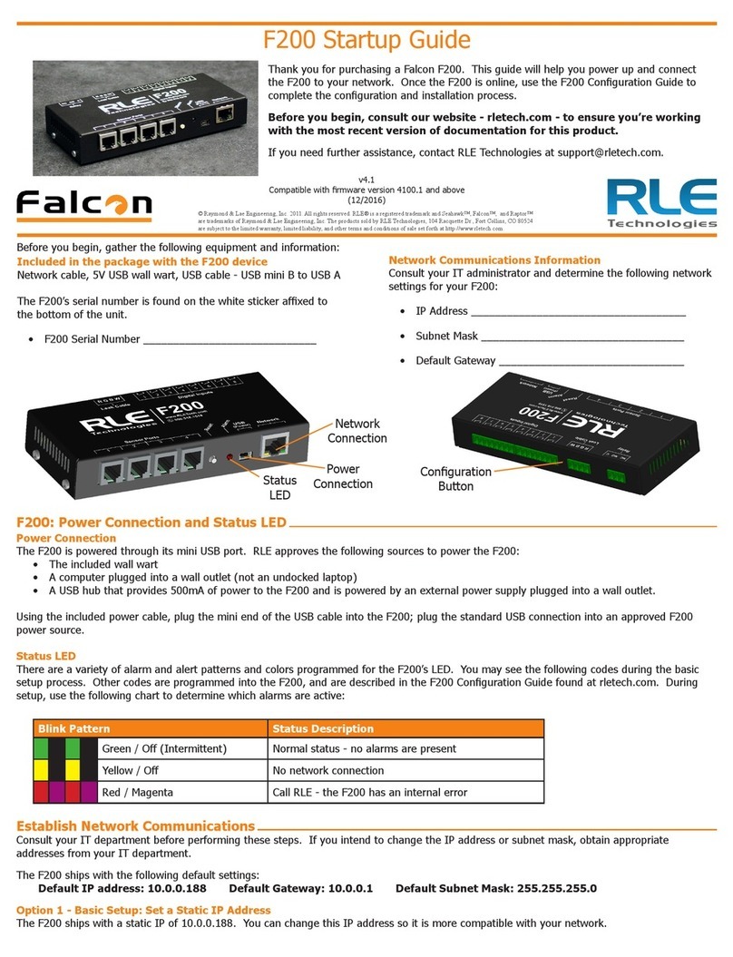
Other RLE Technologies Measuring Instrument manuals

RLE Technologies
RLE Technologies WiNG-MGR Instruction Manual

RLE Technologies
RLE Technologies Falcon FMS User manual

RLE Technologies
RLE Technologies Falcon F200 User guide

RLE Technologies
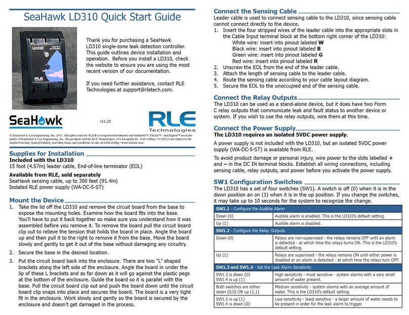
RLE Technologies SeaHawk LD310 User manual

RLE Technologies
RLE Technologies WiNG-CO2 User manual

RLE Technologies
RLE Technologies Falcon WiNG-RXT Use and care manual

RLE Technologies
RLE Technologies WiNG-MGR v2 User manual