manuals.online logo
Brands
  1. Home
  2. •
  3. Brands
  4. •
  5. RLE Technologies
  6. •
  7. Measuring Instrument
  8. •
  9. RLE Technologies WiNG-CO2 User manual

RLE Technologies WiNG-CO2 User manual

© Raymond & Lae Engineering, Inc. 2011. All rights reserved. RLE® is a registered trademark and Seahawk™, Falcon™, and Raptor™ are trademarks
of Raymond & Lae Engineering, Inc. The products sold by RLE Technologies, 104 Racquette Dr., Fort Collins, CO 80524 are subject to the limited
warranty, limited liability, and other terms and conditions of sale set forth at https://www.rletech.com.
Supplies for Installation
WiNG-CO2 Sensor
Small athead screwdriver
Installation Instructions
1. WiNG-CO2 sensors can only be seen by an RLE WiNG controller with the
following rmware requirements:
Device Minimum Required Firmware Version
WiNG-MGR v3.6.0
WiNG-MGR v2 v1.0.27
BMS-WiNG v3.2
If your device’s rmware is older than necessary, download the latest
rmware from the RLE website (rletech.com) and update your device.
2. Remove the lid from the sensor enclosure. The lid has one large tab at the
top and two small tabs at the bottom that secure it to the sensor base.
Squeeze the top of the lid to release the large tab. Pivot the top of lid out
from the base and gently separate the two bottom tabs from the base.
NOTE: The serial number is printed on a white label on the outside of the
sensor lid. The serial number is unique to each sensor and you will need to
refer to this number throughout the life span of the device.
3. Remove the circuit board from the base to expose the mounting holes.
Before you take it apart examine how the board ts into the base. You’ll have
to put it back into the base so make sure you have a clear understanding of
how it was assembled before you remove it.
4. To remove the board pull the circuit board clip out to relieve the tension that
holds the board in place. Angle the board up and then pull it to the right to
remove it from the base. Move the board slowly and gently to get it out of
the base without damaging any circuitry.
5. Secure the base in the desired location. Select a location for the transmitter,
keeping the following in mind:
• For best reception, mount the enclosure base as high o the oor as you
can with the most direct/clear line of sight to the controller.
• Do not mount the transmitter behind metal objects.
6. Put the circuit board back into the enclosure. Angle the board in under the
lip of the L brackets and as far down as it will go against the plastic pegs at
the bottom of the enclosure. Guide the board so it is parallel with the base.
Pull the circuit board clip out and push the board down until the board clip
securely snaps into place. The board is a very tight t in the enclosure. Work
slowly and gently so the board isn’t damaged.
7. Each WiNG-CO2 sensor must be congured for its environment during
deployment. The sensor will not operate properly until all steps of this initial
conguration procedure are completed:
a. Remove the batteries from the sensor. Wait 20 seconds for power to
dissipate.
b. Compensate for Altitude: Altitude has a signicant impact on CO2
readings - for example, a CO2 reading taken at 10,000ft will have a
measurement change of 44% from the same reading taken at sea
level. Each WiNG-CO2 must be congured to compensate for the
altitude of its location.
Use a small athead screwdriver to point the arrow of the rotary switch
to the setting that corresponds with the closest altitude setting:
Rotary Switch
Setting
Altitude (ft) Altitude (m) CO2 Measurement
Change (%)
0 0 0 0
1 500 153 3
2 1,000 305 5
3 1,500 458 7
4 2,000 610 10
5 2,500 763 12
6 3,000 915 15
7 3,500 1,068 17
8 4,000 1,220 19
WiNG-CO2 Quick Start Guide
Thank you for purchasing a WiNG-CO2 wireless sensor. Before you install
your device, consult rletech.com to ensure you’re working with the most
recent version of documentation available. If you need further assistance,
please contact RLE Technologies at [email protected].
v06.21
Rotary Switch
Setting
Altitude (ft) Altitude (m) CO2 Measurement
Change (%)
9 4,500 1,373 22
A 5,000 1,525 24
B 6,000 1,830 28
C 7,000 2,135 32
D 8,000 2,440 36
E 9,000 2,745 40
F 10,000 3,050 44
c. Set the Auto-Zero Function: When auto-zero is on, the sensor
automatically re-calibrates every two weeks - the zero point of the CO2
module resets to the lowest point detected during the past two weeks.
This operation relies on there being a regular period of unoccupancy
in the space, such as at nights or weekends, to ensure levels drop to
around 400ppm. By default, each sensor is shipped with auto-zeroing
turned ON.
• Auto-Zero ON: The white jumper is in the leftmost “AUTO”
position, covering the farthest left and middle pins.
• Auto-Zero OFF: The jumper in the rightmost “OFF” position,
covering the middle and farthest right pins.
d. Congure the Zero Point in Fresh Air: The CO2 module must now be
congured with the fresh air setting for its location. Expose the sensor
to fresh air outside or in an unoccupied area for 5-10 minutes.
e. The measurement interval on the WiNG-CO2 is by default set to 2
minutes. This interval is congurable. If you’d like to change the
measurement interval, you must do so now. Refer to the WiNG-CO2
Measurement Interval Conguration Guide for complete instructions.
f. The initial conguration is complete, and now you must save the
settings you’ve just programmed:
1. Hold the push button on the top of the sensor.
2. While continuing to hold the button, reinstall the batteries. The
LED will turn white to indicate that the sensor is in conguration
mode.
3. Continue to hold the push button. The LED will then turn green to
indicate that conguration has completed successfully.
4. Once the LED turns green, release the push button.
5. Check the WiNG-MGR web interface or BMS and verify the sensor appears
in the list of sensors connected to it. You may need to click the Sensor
Discovery button in the WiNG-MGR web interface to allow the unit to nd
this new sensor.
6. Check the WiNG-MGR web interface or BMS to make sure the sensor status
reports accurately.
LED
3.6V
Lithium
Batteries
Antenna
Circuit
Board
Clip
L Brackets
Plastic
Peg
Antenna Guides
Rotary
Switch Auto-Zero
Jumper
CO2 Sensor
Push
Button
Plastic
Peg
7. Replace the lid, ensuring that the antenna is held in place by the antenna
guides and feeds out the vent hole in the side of the enclosure. Do not pinch
the antenna between the lid and the case.

Other RLE Technologies Measuring Instrument manuals

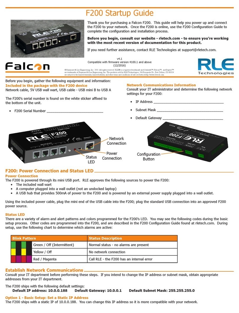
RLE Technologies Falcon F200 User guide

RLE Technologies

RLE Technologies Falcon F200 User guide

RLE Technologies Falcon FMS User manual

RLE Technologies

RLE Technologies Falcon FMS User manual

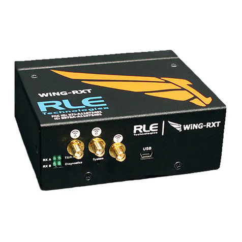
RLE Technologies Falcon WiNG-RXT Use and care manual

RLE Technologies

RLE Technologies Falcon WiNG-RXT Use and care manual

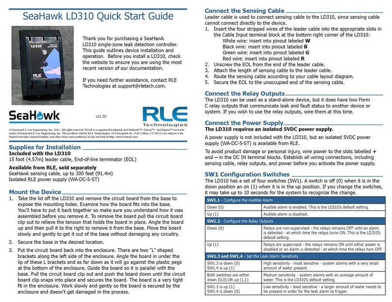
RLE Technologies SeaHawk LD310 User manual

RLE Technologies

RLE Technologies SeaHawk LD310 User manual

RLE Technologies LD5100 User manual

RLE Technologies

RLE Technologies LD5100 User manual

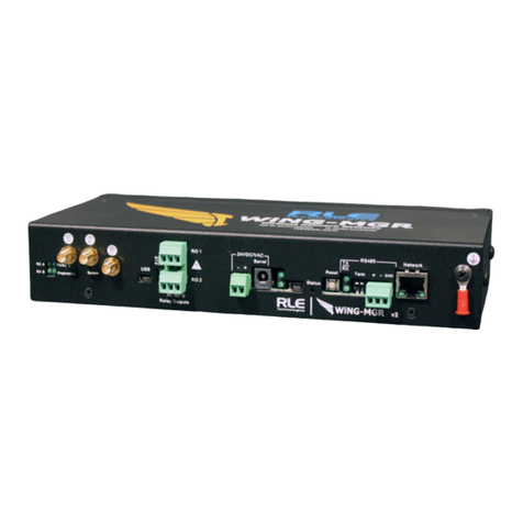
RLE Technologies WiNG-MGR Instruction Manual

RLE Technologies

RLE Technologies WiNG-MGR Instruction Manual

RLE Technologies WiNG-MGR v2 User manual

RLE Technologies

RLE Technologies WiNG-MGR v2 User manual

Popular Measuring Instrument manuals by other brands

FRC Insight Series manual

FRC

FRC Insight Series manual

Horus Mini user manual

Horus

Horus Mini user manual

Digatron DT-31SN operating instructions

Digatron

Digatron DT-31SN operating instructions

Mitsubishi ME96NSR Programming manual

Mitsubishi

Mitsubishi ME96NSR Programming manual

Gentec S-LINK user manual

Gentec

Gentec S-LINK user manual

Simpson 897 Operator's manual

Simpson

Simpson 897 Operator's manual

Hasco Z 251 operating instructions

Hasco

Hasco Z 251 operating instructions

Heska Element COAG Operator's guide

Heska

Heska Element COAG Operator's guide

Process Sensors MCT466-QC User guide manual

Process Sensors

Process Sensors MCT466-QC User guide manual

Gamatronic GMAC-5 user guide

Gamatronic

Gamatronic GMAC-5 user guide

MADDALENA ElecTo Bulk installation instructions

MADDALENA

MADDALENA ElecTo Bulk installation instructions

Mastech MS2128A Operation manual

Mastech

Mastech MS2128A Operation manual

London Electronics Fusion-L 6 digit Connection details, scaling and general information

London Electronics

London Electronics Fusion-L 6 digit Connection details, scaling and general information

Pendulum CNT-90 user manual

Pendulum

Pendulum CNT-90 user manual

IFM Electronic efector 300 SV Series operating instructions

IFM Electronic

IFM Electronic efector 300 SV Series operating instructions

ATEQ VT31 user guide

ATEQ

ATEQ VT31 user guide

Zoetis vetscan SA user manual

Zoetis

Zoetis vetscan SA user manual

GE CheckPoint Quick setup guide

GE

GE CheckPoint Quick setup guide

manuals.online logo
manuals.online logoBrands
  • About & Mission
  • Contact us
  • Privacy Policy
  • Terms and Conditions

Copyright 2025 Manuals.Online. All Rights Reserved.