RLH Industries Smart 8 User manual

Smart8Relay Output
User Guide
U-123 2018B-0330
RLH Industries, Inc.

!RLH Industries, Inc.!
Copyright © 2017 RLH Industries, Inc. All rights reserved.!
No part of this document may be copied or distributed without
permission.
The RLH logo may not be used for commercial purposes without the
prior written consent of RLH and may constitute trademark
infringement.
Other company and product names mentioned herein are trademarks
of their respective companies. Mention of third-party products is for
informational purposes only and constitutes neither an endorsement
nor a recommendation. RLH assumes no responsibility with regard to
the performance or use of these products.
The information contained in this document is the property of RLH
Industries, Inc. and may not be reproduced or disseminated to third
parties without the express written permission of RLH.
Every effort has been made to ensure that the information in this
manual is accurate. RLH is not responsible for printing or clerical
errors. Because we are constantly seeking ways to improve our
products, specifications and information contained in this document
are subject to change without notice.
RLH Industries, Inc.!
936 North Main Street!
Orange, CA 92867!
!
Ph. 714 532-1672!
email: info@fiberopticlink.com!
www.fiberopticlink.com
""
2

Contents
1.!Important Information
Intended Audience 5
Conventions 5
Standard Features 6
Panel Layout 7
Front Panel#7
LED Identification#7
System Alarm Contacts#8
Bottom Panel#8
Rear Panel#8
3.!Before Installing
Prepare for Installation 9
Check for shipping damage#9
Verify system contents#9
Site Requirements 9
Site selection#9
Typical installation environments#9
Required power sources#9
4.!Installation
Getting Started 10
Before starting#10
Install the Smart Relay Output#10
Connect wiring to Relay Output Contact Terminals#10
Relay Output Maximum Ratings#10
Connect Ethernet cable#10
Connect power#11
System alarm wiring#11
Start the system#11
5.!Establishing Connection to Device
General Connection 12
Default Settings#12
Assigning a Static IP Address 12
Steps for Window XP#12
Steps for Windows 7#15
6.!Device Configuration
Network Address Configuration 18
Email / SMTP Server Configuration 19
Contents 3

1.#Important Information
Relay Setup 20
Relay Control 21
System Link Configuration 22
Date/Time – NTP vs Local Time 24
SNMP Community Configuration 25
ModBus TCP 26
Function 1: Read Coil#27
Function 3: Holding Register"# 27
Function 6: Write Single Register#27
Function 16: Write Multiple Register#28
DNPv3 TCP 29
DNPv3 Device Profile#30
DNPv3 Implementation Object Table#31
DNPv3 Control Relay Output Block (CROB) Table#32
Relay Output Log 33
Administration Tasks 34
Change Password#34
Rebooting#34
Set to Factory Defaults#34
Hard Reset#35
Software Factory Reset#35
7.!Configuration Examples
Event Consolidation - Many Inputs to One Output 36
8.!Application Examples
Contact Closure over Ethernet - One to One (TCP) 37
Contact Closure over Ethernet - One to Many (UDP) 37
Event Consolidation - Many Inputs to One Output 38
Remote Relay Control 38
9.!Specifications
General Specifications 39
10.!Ordering Information
System Models 40
11.!Support
Technical Support 41
Contact Information 41
Contents4

Intended Audience
This manual is intended for use by qualified technology experts and includes references to industry standard
terminology and practices. Every effort has been made to ensure the information in this manual is accurate,
however due to constant product improvement specifications and information contained in this document is
subject to change without notice. For the most up to date information on this product you can visit
www.fiberopticlink.com.
Conventions
Symbols for notes, attention, and caution are used throughout this manual to provide readers with additional
information, advice when special attention is needed, and caution to prevent injury or equipment damage.
Notes: Helpful information to assist in installation or operation.
Attention: information essential to installation or operation.
Caution: Important information that may result in equipment damage or injury if ignored.
General Safety Practices
RLH recommends that installation and service personnel be familiar with the correct handling and use of
electrical and network equipment prior to use. RLH also recommends that installation and service personnel
follow all safety precautions including the use of protective personal equipment as required.
Caution - Severe Shock Hazard!
• Always remove source voltage using proper lockout procedures prior to installation and service.
• Never wire any relay outputs with hot (live) connections.
• Remove the terminal block when wiring.
• Check that all equipment has been properly locked out before restarting or configuring the device.
Contents 5

Ethernet I/O
The Smart Relay Output is an Ethernet device with 8 Integrated controllable relays. The device allows for web
based control of the relays and may be integrated into distributed control and network management systems to
allow those systems to control it's Relays. Each of the Relays can be individually configured to send customized
emails and notifications when an event is triggered. The device supports a wide variety of protocols it is
compatible with over Ethernet. Integration options supported are: SNMPv1,2c,3, SNMP Traps !
(SNMP 1, 2vc), Modbus TCP featuring addressable registers, and DNPv3 TCP for integration with utility and
other automation control systems.
Contact Closure Over Ethernet
The RLH Smart Relay Output may be paired with an RLH Smart Input Sensor. When using RLH's System Link
feature, the two devices become linked establishing a tunnel over an Ethernet network and will transport a
digital outputs being received by the Input Sensor through the Ethernet tunnel to the linked Relay Output
device. The System Link feature can be set up via: One to One, Many to One, and One to Many allowing for
event distribution and consolidation as needed.
Standard Features
Rugged Design - Operating temp. -40°C ~ 70°C
Intuitive embedded web interface for configuration
System Link - Pair with a Input Sensor for Alarm Transportation over Ethernet
Event Consolidation – Pair with up to 8 Input Sensors to consolidate remote alarms to one location
Alarm Distribution - Multiple output units may be paired with one Input Sensor
IGMP V2 supported to enable multicast routing in one to many configurations
Remote Control of 8 Relays
Custom email notifications for each output
Each relay supports up to 3 Amps or 60 Watts
Advanced SMTP integration allowing for SSL and TLS based authentication
Integration options include: SNMPv1, 2c, 3, SNMPv1,2c Traps, Modbus TCP, and DNPv3 TCP
Output event log with time stamps
System power ranges available: 24-48VDC, 125VDC, & 12VDC.
10/100 Fast Ethernet Port
Limited Lifetime Warranty
Made in the U.S.A."
Introduction6
•Verify or repair before continuing

Panel Layout
Front Panel
The front panel contains all the relay output terminals, LED’s, and the Ethernet port.
!
Front Panel Features
LED Identification
SERIES
Smart
1 5
LNK
ACT
2 6
3 7
4 8
10/100M
ETHERNET
PWR
STS
LNK
RLH Industries, Inc.
RELAY
OUTPUT
OUTPUTS
OUT 1 OUT 2 OUT 3 OUT 4 OUT 5 OUT 6 OUT 7 OUT 8
RX
Power LED
Status LED
System Link LED
1~8 Output LED’s
Ethernet Link LED
Ethernet Activity LED
1~8 Relay!
Outputs
Power & Alarm
Terminals
Ethernet Port
LED
Name
Color
Status
Condition
Outputs
1-8
Contact Output
Green
ON
Relay is energized
OFF
Relay is not energized
PWR
Power Failure
Green
ON
DC input power OK
OFF
DC input power failed
STS
CPU Failure
Green
Blinking
CPU operating normally
Solid (On or Off)
CPU failure
LNK
System Link
Green
ON
Paired via TCP connection
OFF
Not paired with output unit
LNK
Ethernet Link Down
Green
ON
Ethernet link is present
OFF
No Ethernet link present
ACT
Ethernet Activity
Orange
Blinking
Ethernet is active
OFF
Ethernet is not active
Introduction 7

System Alarm Contacts
• Alarms on power failure.
• Alarms when Ethernet Link Down.
• Can be configured to alarm when the system link to a paired Input Sensor is disconnected.
Bottom Panel
The bottom panel contains the power and alarm terminals.
!
Bottom Panel Features
Rear Panel
The DIN clip for mounting the system is mounted onto the rear panel. Insert a flat head screwdriver into the
release slot at the bottom of the DIN clip and pull down to remove the system from the DIN rail.
!
RESET
PWR2
PWR1
COM
NO
ALARM
NC
Alarm Terminal
Reset Button
3.9”
100mm
2.0”
51mm
Power Terminals 1 & 2
5.0”
127mm
DIN Clip
Release!
Slot
Rear Panel Features
Smart Relay!
Output
Smart Relay!
Output
1
Hook top of
DIN clip first
2
Rotate and
snap into
position
DIN!
Rail
DIN!
Rail
DIN Rail Mounting
Introduction8

3.#Before Installing
Prepare for Installation
Check for shipping damage
Carefully unpack and inspect the device. Contact RLH immediately if any components are damaged or missing.
Verify system contents
• Smart Relay Output device
• Attached DIN Clip
• Correct model type for intended application.
Site Requirements
Site selection
Locate the Smart Relay Output to allow easy access to the equipment. Leave at least 3 inches (7.62 cm)
clearance in the front. The device is temperature hardened, but must be mounted indoors or inside an outdoor
rated enclosure.
Typical installation environments
• NEMA 4X enclosures
• RLH 19” rack mount DIN rail brackets
• Control cabinets
• T-35 DIN rail
Required power sources
The Standard RLH Smart Relay Output system accepts 24~56VDC. RLH also offers optional power
compatibility to both Low DC (12 Volts) and High DC Power (125 Volts) for enhanced compatibility with solar
and utility battery systems.
Before Installing 9

4.#Installation
Getting Started
Before starting
• Review the safety information in section 1. Important Information
• Familiarize yourself with the Smart Relay Output as described in section 2. Introduction
• Have a suitable installation environment with the correct source voltage.
Install the Smart Relay Output
• Mount the 8 Channel Relay Output to T-35 DIN rail.
Connect wiring to Relay Output Contact Terminals
• There are 8 pairs of output contact terminals located on the front panel of the 8 Channel Relay Output.
• The pluggable contact terminals may be removed if needed and will accept wire sizes 16~26 AWG.
• Fully seat the terminal block back into the connector socket before operating the system
Relay Output Maximum Ratings
RLH Recommends using a external relay for applications where voltage and amperage exceed the devices
built-in Relays specifications. Exceeding the maximum ratings may lead to premature failure or improper
operation of the Relays.
Connect Ethernet cable
• Attach the Ethernet cable to the RJ-45 Ethernet port located on the front panel of the Smart Relay Output. Verify
the Link indicators are ON to ensure you have connectivity to your network.
Relay Maximum Ratings
115VAC
1.08A
125VA
12VDC
3.00A
36 Watts
24VDC
2.50A
60 Watts
48VDC
1.25A
60 Watts
130VDC
0.46A
60 Watts
220VDC
0.27A
60 Watts
Quick Start Guide10

Connect power
The Smart Relay Output has redundant power terminals to accommodate a backup power supply in the event
of an outage. Follow these steps when attaching wires to power terminals located on the bottom of the module.
• Check that DC power source voltage matches the accepted voltage range of the device.
• Remove power from the DC power source prior to connecting to the Smart Relay Output.
• Connect the DC power cables to the terminal pairs. The power terminals are not polarity sensitive.
• Energize the power source. The PWR LED will be ON indicating that the system has power.
System alarm wiring
Connect alarm relay monitoring equipment wire pair to the alarm contact on the bottom of the device.
• Use the NO or NC contact positions as required.
• The alarm terminal block may be removed and accepts wire sizes 16~26 AWG.
• Fully seat the terminal block back into the connector before operating the system.
Start the system
Once a local power source is connected and turned on the PWR LED will turn ON. The STS LED will be
blinking to let you know the device is operating normally.. "
Installation 11

5.#Establishing Connection to Device
General Connection
To initially connect to the RLH Smart Relay Output you must access the device by its default IP address as
listed below:
Default Settings
!
In most cases you will need to assign a temporary static IP to your workstation to initially access the RLH Smart
Relay Output web page. The assigned temporary address should be within the same subnet as the default
address.
Example Client Device Address:
• IP: 192.168.2.10
• Subnet: 255.255.255.0
Now access the device via: http://192.168.2.17
Assigning a Static IP Address
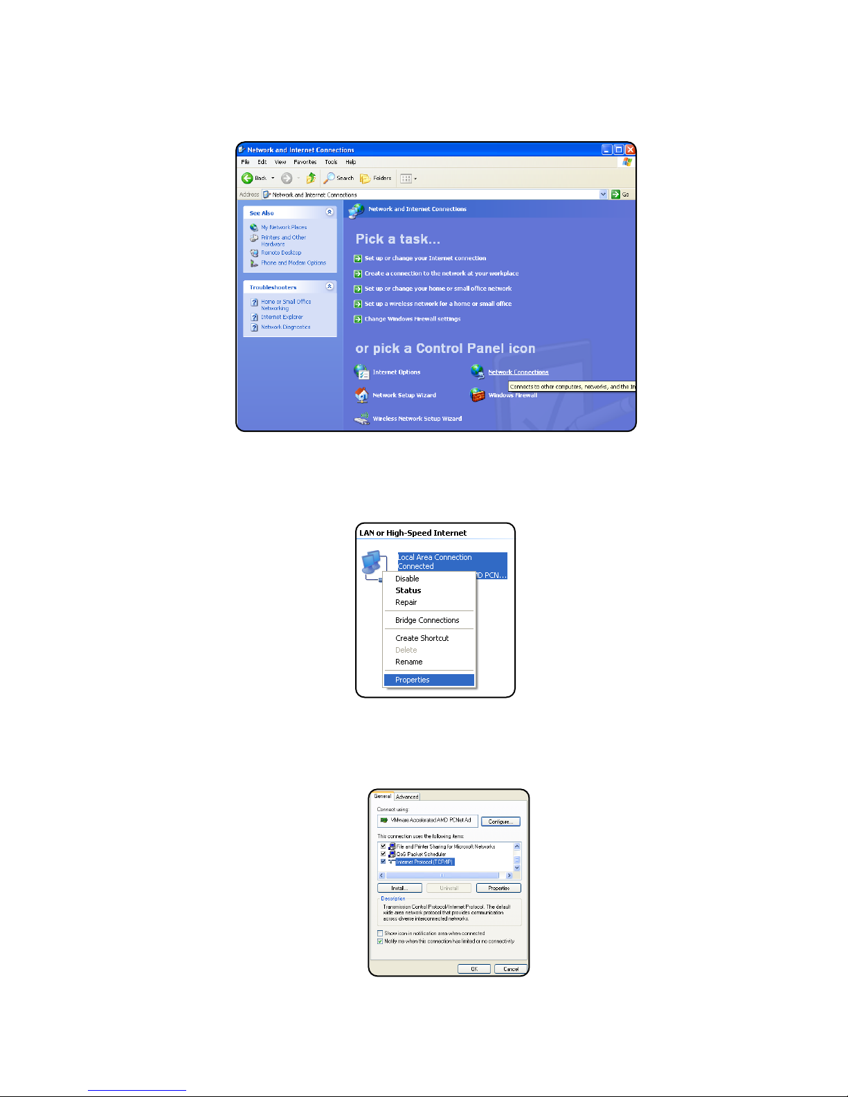
Steps for Window XP
First: Go to windows XP control panel and select Network and Internet Connections.!
!"
IP Address: 192.168.2.17
Subnet: 255.255.255.0
Username: admin
Password: admin
Default IP Address
Default Username/Password
Establishing Connection to Device12

Next: Select Network Connections
!
Next: Right-click on the adapter you want to set the IP for and select Properties.!
!
Next: Highlight"Internet Protocol (TCP/IP)"and click the Properties button.!
!
Establishing Connection to Device 13
Next: Select Network Connections
!
Next: Right-click on the adapter you want to set the IP for and select Properties.!
!
Next: Highlight"Internet Protocol (TCP/IP)"and click the Properties button.!
!
Establishing Connection to Device14

Next: Change the IP, Subnet mask, Default Gateway, and DNS Server Addresses. When you are finished
click OK.
!
Note: You will need to close out of the Network Connection Properties screen before the changes go into
effect.
Finally: Verify IP Address:
• In the Run box type in"cmd"and click OK.
• Then at the prompt type in"ipconfig"and hit Enter. This will show the IP address for the network adapter you
changed.
Steps for Windows 7
First: To a static IP address in Windows 7, type"network and sharing"into the Search box in the Start Menu and
select Network and Sharing Center when it comes up.
!
Establishing Connection to Device 15

Next: When the Network and Sharing Center opens, click on"Change adapter settings.
!
Next: Right-click on your local adapter and select Properties.
!
Next: In the Local Area Connection Properties window highlight"Internet Protocol Version 4 (TCP/IPv4)"then
click the Properties button.
!"
Establishing Connection to Device16

Finally: Now select the radio button"Use the following IP address"and enter in the correct IP, Subnet
mask, and Default gateway that corresponds with your network setup. When you’re finished click OK.
!
Note: Now you can open the command prompt and do an"ipconfig to see the network adapter settings have
been successfully changed.
Establishing Connection to Device 17

6.#Device Configuration
Network Address Configuration
!
Network Address Configuration Screen
Note: If unsure of the address to assign your device you may wish to consult your network administrator for the
correct addressing information for your network
Settings
Description
Mac Address
Read only field will display the mac-address of your device.
Host Name
Enter the host name which your DNS server will register your device as.
Enable DHCP
If checked, this option allows you to automatically obtain addressing information
from your networks DHCP server.
IP Address
Set a static IP address for which you wish to assign to the device.
Subnet Mask
Set subnet mask you wish to use.
Gateway
Set the default gateway the device will use.
Primary DNS
This will be the first server your device connects to for translating URLs and Fully
Qualified Domain Names (FQDNs).
Secondary DNS
In case of an outage in the primary DNS server the device will attempt to use the
secondary DNS as a backup.
Device Configuration18

Email / SMTP Server Configuration
!
SMTP/Email Configuration Screen
Note: SSL connections will only support up to 1024 Bit certificates.
Settings
Description
SMTP Server
Enter the FQDN or the IP address of the email server you wish to use.
Port
Set to 25 by default.
Encryption
None - No encryption will be used when communicating with SMTP server!
SSL (V2) - Encryption will be used when communicating with SMTP server
TLS (V1.1) - Encryption will be used when communicating with the SMTP server
Username
Enter in your SMTP server username.
Password
Enter your SMTP server password.
From
This will be the from address the device uses in email notifications.
To
Email Address for the To field for SMTP notifications.
CC
Email Address for the CC field for SMTP notifications.
Checkbox!
(Send Test Email)
If checked the device will send a test email when the "Save Settings" !
button is clicked.
Device Configuration 19

Relay Setup
The Relay Setup page allows you to assign names, descriptions, and enable email notifications for each relay.
!
Relay Setup Screen
Settings
Description
Name
Assign a name to each relay
Enable Email
Notifications
Enable email notifications when the relay changes state. Email notifications will
include the device Hostname, relay name, relay description, relay status, and a
time stamp if NTP is configured.
Description
Provide a description for each relay
Save Settings
Apply the new setting information by clicking the button at the bottom of the page
Device Configuration20
Table of contents
Popular Other manuals by other brands

Bosch
Bosch TR2000 Series Installation and operating instructions

Red Sea
Red Sea REEFER DLX 425 Assembly manual

Whelen Engineering Company
Whelen Engineering Company Super-LED FDCT10BR installation guide

ELWING
ELWING HALOKEE user guide

Pioneer
Pioneer MVH-X360BT owner's manual

Arregui
Arregui Supra Instruction manual and guarantee


ETAS
ETAS ES5338.1 user guide

Paradyne
Paradyne 9261 installation instructions

Beauty Works
Beauty Works Mini Microdermabrasion Instructions for use

Aquatlantis
Aquatlantis Tecatlantis EASY LED UNIVERSAL 2.0 manual

Toyotomi
Toyotomi TD-C210 operating manual

Craftwell
Craftwell Cut'n'Boss Limited Edition user manual