RMG 530-E-WG User manual

SERVING THE GAS INDUSTRY WORLDWIDE
Operation and Maintenance Instructions / Spare Parts
FLOW CONTROL VALVE RMG 530-E-WG 530.24
RMG Regel + Messtechnik GmbH
DN 200/200 to DN 400/400 Edition 10/2008

530.24 S.02
Contents Page
1. General information 3
1.1 Safety information 3
2 Specific maintenance instructions 4
2.1 Disassembling and replacing seals 4
2.2 Checking components, assembly 4, 5
2.3 Tightening torques 5
2.4 Lubricants 5
3. Spare parts 6
3.1 Spare parts drawing 6, 7
3.2.1 Spare parts lists DNE 200 thru DNE 250 8, 9
3.2.2 Spare parts lists DNE 300 thru DNE 400 10, 11
4. Parts for maintenance purposes 12

530.24 S.03
Note
Caution
!
Danger of damage to property and/
or the environment
important additional information
Eye catcher used for:
Danger
!
Danger to life and limb
1. General information
All persons involved with the assembly, operation and/or maintenance of RMG 530 volume control valves must read and
understand all of the following documents:
–Technical product information brochure 530-E-WG- it contains the technical data and dimensions of the equipment as well as
instructions concerning set-up and mode of operation.
-General operating manual for gas pressure regulators and safety devices- this RMG document contains information on
assembly and operation as well as general information on troubleshooting.
-Operating and maintenance instructions/spare parts 530.24- this document contains more detailed information on assembly
and operation of RMG volume control valves 530-E-WG.
There are national laws and regulations for all sorts of jobs on gas pressure regulators, from planning to maintenance. Be sure to
comply. (In Germany, for instance, DVGW work sheets G 600, G 459/II, G 491 and G 495.)
Inspection and maintenance intervals depend mostly on operating conditions and the nature and properties of the gas. There are
no general rules or recommendations for intervals. For Germany, we recommend to consider maintenance intervals as stated in
DVGW work sheet G 495 in a first instance. However, in the mid-term, intervals must be adapted to the requirements of each
specific equipment.
During maintenance, components must be cleaned and then checked thoroughly. This is necessary even if there have been any
unusual observations during operation and/or functional testing. Checks must focus, in particular, on diaphragms and seals and all
movable parts and their respective bearings. Any and all defective parts must be replaced with new ones. The same applies to
O-rings removed during disassembly.
Item numbers mentioned in the specific operating and maintenance instructions correspond with the numbers in the spare parts
lists and drawings.
Some parts in the lists and drawings are marked with a letter “W”. We recommend you always have a reserve of those parts in
stock for maintenance purposes. Those spare parts are put together in another separate list at the end of the spare parts list.
1.1 Safety information
In this manual, safety information is highlighted by means of the following titles and eye catchers:

530.24 S.04
2. Specific maintenance instructions
Under normal circumstances, maintenance jobs may be limited to the sealing elements of the drive shaft and actuator
(zero shut-off) and the threads of the spindle and mitre gear.
2.1 Disassembling and replacing seals
Use the electrical actuator to move the valve sleeve to the UP position. (Limit switch UP switches off.)
Remove screws/bolts (37) to dismount the rotary drive + cap (5).
Check the thread and feather key groove of spindle (23): Worn?
- The sides of the thread must be smooth– no score marks.
- The unit consisting of the spindle+ rotary drive must not show any axial play.
- The spindle must screw easily into the rotary drive.
- Lubricate the spindle (23), internal thread of the rotary drive (15), feather key (24) and key-feather
groove generously.
Mark the position of the drive shaft (3) with a view to actuator (16) and in relation to the feather key (2)
and position of plate (53). (Important during re-assembly.)
Caution
!
Note
•
•
•
•
•
•
•
•
•
•
•
•
Mark the position of spindle (23) with a view to bush2 (26). (Important during re-assembly.)
Note
•
•
•
Turn drive shaft (3) to move the spindle (23) up and/or down all the way to the mark. The marks on the
shaft (3) and plate (53) must match.
Note
Loosen the cheese head screw in adjusting nut (4) and remove the nut.
Remove the cheese head screws (7).
Remove the plate (52) from housing (16) by screwing in two 2 M10 eye bolts.
After you removed the cheese head screws (56), pull bush (58) out of plate (53).
Replace the seal (54). Consider the proper position when fitting: The coil spring must point in the direction of the pressure side.
Remove the device from the system and place it on its inlet flange. Remove the cheese head screws (29) and pull
out the outlet part (34) towards the top.
Discard the O rings (28+ 45) and put in new ones.
Loosen the cheese head screw in adjusting nut (41) and remove the nut. Remove the valve sleeve (40). Use two M8 eye bolts to
pull it out of the device .
Loosen screws/bolts (47) and remove ring segment (32). Discard seal elements (43+ 44) and place new ones.
Remove release sleeve (38). Use two M6 eye bolts to pull it out of the device . Discard the O ring (64), compensation ring (62),
guide-ring (61) and seal (63) cpl. w/support ring (60). Use new ones. Clean the grease chamber (48) and fill with new lubricant
(48).
Loosen the cheese head screws (25) in bush2 (26), and pull out bush2. Remove and clean the feather key (24).
Screw out the cheese head screws (20) and pull out bush1 (22). Remove the spindle (23).
2.2 Checking components, assembly
Clean ALL the components. Find and grease all components mentioned in lubricant table 2.4 before you put them back in.
Grease ALL screws+ bolts before you put them back in. Consult table 2.5 for tightening torques MA.
Insert spindle (23) into rotary drive (15). Screw down bush1 (22) onto rotary drive. Place feather key (24) into the groove
on spindle (23). Place bush2 (26) on top. Use the cheese head screws (25) and lock washers (27) to tighten everything.

•
•
•
•
•
•
•
•
Be sure to mount the shaft washer (49) and housing washer (51) the right way.
Note
•
•
•
DN Screws & bolts– item no.
7 10 13 18 20 25 29 35 37 47 56
200/200
200/250(VS200)
200/300(VS200) 190 20 12 20 30 10 350 45 45 5 4
250/250(VS200)
300/300(VS200)
300/300 510
400/400 1100
Tightening torques MA in Nm
Components Lubricants RMG part no.
•
•
Spindle (23)
Feather key (24) (Grease well!) Silicone grease 27052
Valve sleeve (40), grease chambers (48),
thrust bearings (49 - 51)
Seal elements (Grease lightly!)
and all the fastening screws Silicone grease 27081
530-24 S.05
•
350 80 40 40 40 8 45 45 8 4
Danger
!
Risk of accidents. Secure the flow restrictor against slipping.
Pull the special washer (31) over the spindle (23).
Place the compensation ring (62) in the pit of the actuator housing (16) provided for that purpose.
Grease and place the new Oring (64), GT ring/ Oring (63) cpl. with support rings (60) and guide ring (61) into the
groove of the release sleeve (38). (Don't forget to clean the groove.) Fill the grease chamber (48) with lubricant.
Grease and place the Glyd ring (43) and Oring (44) in the flow restrictor (38). Use the screws (47) to fix the ring
segment (32) to the flow restrictor.
Before you mount them: pull the flow restrictor (38) over the valve sleeve (40).
Use eye bolts to fix the valve sleeve (40) and flow restrictor to the actuator (16).
Use the special washer (33) and adjusting nut (41) t fix the valve sleeve to the spindle (23). Tighten well.
Fix the adjusting nut (41) use cheese head screws.
Grease and place the Oring (28) + (45) into the groove provided for that purpose. Screw actuator housing2 (34)
onto actuator housing1 (16).
Put the device right side up again. Clean, grease and replace the lower thrust bearing.
Place the plate (52) and fix to housing (16).
Now, mount the upper thrust bearing. Be sure to mount the shaft washer (49) and housing washer (51) the right way.
Tighten the adjusting nut (4) LIGHTLY and fix with a cheese head screw.
Set the electrical drive to end bearing position “Up”, place cap (5) and mount onto the drive shaft (3). (Don't forget to
grease the shaft.)
With this procedure, it will not be necessary to adjust the limit switches of the electrical drive system.
2.3 Tightening torques MA
2.4 Lubricants

17 18 19 20 21 22 23 24 25 26 27 28 29 30 31 32 33 34
W
35 36 37 38 39 40 41 42
3.1 Spare parts drawing RMG 530-E-WG
see page 07
Z
Y
U
V
(rotated
30 degrees)
1
2
3
4
5
52, 53
6
7
W 8
9
10
11
12
13
14
15
16
530.24 S.06

43 W
44 W
45 W
46
47
W 48
51
50
49
52/53
54 W
55 W
56
57
58
59 W
49
50
51
59 W
530.24 S.07
W W W
60 48 61
62 63 64
W W W
Details
Detail “V”
Detail rotated 30 degrees Detail “Z”
Detail rotated 30 degrees
Detail “U”
Detail “Y”

Partno.
530.24 S.08
German abbreviations stand for the following materials:
St ... steel LM ... light metal/alloy GMs ... Brass casting
NSt ... stainless steel Ms ... brass GZn ... Zinc casting
FSt ... spring steel GS ... Cast steel AlBz ... aluminium bronze
NFSt ... stainless spring steel GGG ... spheroidal graphite cast iron K ... synthetic materials
Bz ... bronze GBz ... Bronze casting KG ... gummous synthetic materials
Cu ... copper GLM ... Light metal casting SSt ... foamed materials
Item no. Denomination Num-. W Material DN 200/200 DN 200/250 DN 250/250 DN 250/300
ber VS 200 VS 200 VS 200
3.2.1 Spare parts drawing RMG 530-E-WG
DNE 200 thru DNE 250
1 Rotary drive Please call.
2 Feather key 1 St 26241 26241 26241 26241
3 Shaft 1 St 10030660 10030660 10030660 10030660
4 Adjusting nut 1 St 21195 21195 21195 21195
5 Cap 1 LM 10030638 10030638 10030638 10030638
6 Lock washer 16 FSt 14116 14116 14116 14116
7 Cheese head screw 16 St 10555 10555 10555 10555
8 O ring 1 W KG 100655 100655 100655 100655
9 Lock washer 6 FSt 14112 14112 14112 14112
10 Cheese head screw 6 St 10098 10098 10098 10098
11 Lock washer 4 FSt 14111 14111 14111 14111
12 Louvre 1 St 10030643
13 Cheese head screw 4 St 10587 10587 10587 10587
14 Feather key 1 St 100684 100684 100684 100684
15 Rotary drive 1 St 100689 100689 100689 100689
16 Actuator housing 1, at option:
16 Actuator housing 1 PN 40 1 St 10030623
16 Actuator housing 1 ANSI 600 RF 1 St 10030632 10030632 10030674 10030674
17 Base plate 1 10030840 10030840 10030840 10030840
18 Countersunk screw 4 St 100713 100713 100713 100713
19
20 Cheese head screw 4 St 10098 10098 10098 10098
21 Lock washer 4 FSt 14112 14112 14112 14112
22 Bush1 1 GS 10030837 10030837 10030837 10030837
23 Spindle 1 AlBz 10030648 10030648 10030648 10030648
24 Feather key 1 St 100693 100693 100693 100693
25 Cheese head screw 4 St 10591 10591 10591 10591
26 Bush2 1 St 10030641 10030641 10030641 10030641
27 Lock washer 4 FSt 14111 14111 14111 14111
28 O ring 1 W KG 100694 100694 100694 100694
29 Cheese head screw 28 St 100400 100400 100400 100400
30 Lock washer 28 FSt 14124 14124 14124 14124
31 Special washer 1 St 10030647 10030647 10030647 10030647
32 Ring segment 1 St 10030645 10030645 10030645 10030645
33 Special washer 1 St 10030649 10030649 10030649 1003064
W Parts should be held in stock for maintenance purposes.

Partno.
530.24 S.09
Item no. Denomination Num- W Material DN 200/200 DN 200/250 DN 250/250 DN 250/300
ber VS 200 VS 200 VS 200
34 Actuator housing 2, at option:
34 Actuator housing 2 PN 40 1 St 10030646
34 Actuator housing 2 ANSI 600 RF 1 St 10030635 10030675 10030675 10030679
35 Cheese head screw 4 St 10400 10400 10400 10400
36 Lock washer 12 FSt 14113 14113 14113 14113
37 Cheese head screw 8 St 10400 10400 10400 10400
38 Flow restrictor 1 LM 10030652 10030652 10030652 10030652
39 Eye bolt 1 St 10021 10021 10021 10021
40 Valve sleeve 1 GS 10030843 10030843 10030843 10030843
41 Adjusting nut 1 St 100690 100690 100690 100690
42 Eye bolt 2 St 10590 10590 10590 10590
43 Glyd ring 1 W KG 100658 100658 100658 100658
44 O ring 1 W KG 100659 100659 100659 100659
45 O ring 1 W KG 20618 20618 20618 20618
46 Guide screw 6 St/K 10024447 10024447 10024447 10024447
47 Cheese head screw 6 St 10596 10596 10596 10596
48 Lubricant W 27052 27052 27052 27052
49 Housing washer 2 St 21219 21219 21219 21219
50 Thrust bearing 2 St 21196 21196 21196 21196
51 Shaft washer 2 St 21197 21197 21197 21197
52 Plate, pre-assembled, consisting of: 1 St 10030681 10030681 10030681 10030681
53 Plate 1 St 10030644 10030644 10030644 10030644
54 Shaft seal 1 W KG 21297 21297 21297 21297
55 O ring 1 W KG 21299 21299 21299 21299
56 Cheese head screw 2 St 10497 10497 10497 10497
57 Washer 2 St 10024854 10024854 10024854 10024854
58 Insert seal 1 St 18356757 18356757 18356757 18356757
59 Slide ring 2 W K 21194 21194 21194 21194
60 Support ring 2 W K 100656 100656 100656 100656
61 Guide ring 1 W K 21364 21364 21364 21364
62 Compensation ring 1 W LM 10030662 10030662 10030662 10030662
63 O ring 1 W KG 100655 100655 100655 100655
64 O ring 1 W KG 20545 20545 20545 20545

Partno.
530.24 S.10
3.2.2 Spare parts drawing RMG 530-E-WG
DNE 300 thru DNE 400
Item no. Denomination Num- W Material DN 300/300 DN 300/300 DN 400/400
ber VS 200
1 Rotary drive Please call.
2 Feather key 1 St 26241 26241 26241
3 Shaft 1 St 10030660 10030784 10030620
4 Adjusting nut 1 St 21195 21195 21195
5 Cap 1 LM 10030638 10030627 10030627
6 Lock washer 16 FSt 14116
6 Lock washer 20 FSt 14124 14124
7 Cheese head screw 16 St 10555
7 Cheese head screw 20 St 100683 100683
8 O ring 1 W KG 100655 21387 21387
9 Lock washer 6 FSt 14112
9 Lock washer 8 FSt 14114 14114
10 Cheese head screw 6 St 10098
10 Cheese head screw 8 St 10373 10373
11 Lock washer 4 FSt 14111 14112 14112
12 Louvre 1 St 10030778 10030621
13 Cheese head screw 4 St 10587 10379 10379
14 Feather key 1 St 100684 100684 100684
15 Rotary drive 1 St 100689 100680 100680
16 Actuator housing 1 ANSI 600 RF 1 St 10030678 10030781 10030613
17 Base plate 1 GGG 10030840 10030787 10030844
18 Countersunk screw 4 St 100713
18 Cheese head screw 4 St 10400 10400
19 Lock washer 4 FSt 14113 14113
20 Cheese head screw 4 St 10098 10450 10450
21 Lock washer 4 FSt 14112 14113 14113
22 Bush1 1 GGG 10030837 10030818 10030845
23 Spindle 1 AlBz 10030648 10030770 10030628
24 Feather key 1 St 100693 100685 100685
25 Cheese head screw 4 St 10591 10551 10551
26 Bush2 1 St 10030641 10030772 10030616
27 Lock washer 4 FSt 14111 14112 14112
28 O ring 1 W KG 100694 100840 100676
29 Cheese head screw 28 St 100400
29 Cheese head screw 46 St 10621
29 Cheese head screw 42 St 100703
30 Lock washer 28 FSt 14124
30 Lock washer 46 FSt 14129
30 Lock washer 42 FSt 14140

Partno.
530.24 S.11
Item no. Denomination Num- W Material DN 300/300 DN 300/300 DN 400/400
ber VS 200
31 Special washer 1 St 10030647 10030625 10030625
32 Ring segment 1 St 10030645 10030779 10030615
33 Special washer 1 St 10030649 10030626 10030626
34 Housing 2 ANSI 600 RF 1 St 10030679 10030782 10030614
35 Cheese head screw 4 St 10400 10400 10400
36 Lock washer 12 FSt 14113
36 Lock washer 14 FSt 14113 14113
37 Cheese head screw 8 St 10400
37 Cheese head screw 10 St 10400 10400
38 Flow restrictor 1 LM 10030652 10030769 10030631
39 Eye bolt 1 St 10021 10590 10590
40 Valve sleeve 1 GS 10030843 10030776 10030847
41 Adjusting nut 1 St 100690 100681 100681
42 Eye bolt 2 St 10590 10590 28049
43 Glyd ring 1 W K 100658 100841 100673
44 O ring 1 W KG 100659 100230 100674
45 O ring 1 W KG 20618 20838 100675
46 Guide screw 6 St 10024447 10024447 10024447
47 Cheese head screw 6 St 10596 10320 10320
48 Lubricant W 27052 27052 27052
49 Housing washer 2 St 21219 21219 21219
50 Thrust bearing 2 St 21196 21196 21196
51 Shaft washer 2 St 21197 21197 21197
52 Plate, pre-assembled, consisting of:
53 Plate 1 St 10030644 10030618 10030618
54 Shaft seal 1 W KG 21297 21297 21297
55 O ring 1 W KG 21299 21299 21299
56 Cheese head screw 2 St 10497 10497 10497
57 Washer 2 St 10024854 10024854 10024854
58 Insert seal 1 St 18356757 18356757 18356757
59 Slide ring 2 W KG 21194 21194 21194
60 Support ring 2 W K 100656
61 Guide ring 1 W K 21364 100677 100679
62 Compensation ring 1 W LM 10030662 10030783 10030624
63 O ring 1 W KG 100655
63 GT ring 1 W K 100842 100682
64 O ring 1 W KG 20545 21338 20424

Partno.
530.24 S.12
Partno.
4. Parts for maintenance purposes
DNE 200 thru DNE 250
DNE 300 thru DNE 400
Item no. Denomination Number DN 200/200 DN 200/250 DN 250/250 DN 250/300
VS 200 VS 200 VS 200
Item no. Denomination Number DN 300/300 DN 300/300 DN 400/400
VS 200
8 O ring 1 100655 100655 100655 100655
28 O ring 1 100694 100694 100694 100694
43 Glyd ring 1 100658 100658 100658 100658
44 O ring 1 100659 100659 100659 100659
45 O ring 1 20618 20618 20618 20618
48 Lubricant 27052 27052 27052 27052
54 Shaft seal 1 21297 21297 21297 21297
55 O ring 1 21299 21299 21299 21299
59 Slide ring 2 21194 21194 21194 21194
60 Support ring 2 100656 100656 100656 100656
61 Guide ring 1 21364 21364 21364 21364
62 Compensation ring 1 10030662 10030662 10030662 10030662
63 O ring 1 100655 100655 100655 100655
64 O ring 1 20545 20545 20545 20545
8 O ring 1 100655 21387 21387
28 O ring 1 100694 100840 100676
43 Glyd ring 1 100658 100841 100673
44 O ring 1 100659 100230 100674
45 O ring 1 20618 20838 100675
48 Lubricant 27052 27052 27052
54 Shaft seal 1 21297 21297 21297
55 O ring 1 21299 21299 21299
59 Slide ring 2 21194 21194 21194
60 Support ring 2 10656
61 Guide ring 1 21364 100677 100679
62 Compensation ring 1 10030662 10030783 10030624
63 O ring 1 100655
63 GT ring 1 100842 100682
64 O ring 1 20545 21338 20424

WÄGA W GmbH
RMG Gaselan R + M GmbH
CANADA
ENGLAND
B RMG G
SERVING THE GAS INDUSTRY WORLDWIDE
WWW.RMG.COM
Table of contents
Other RMG Control Unit manuals
Popular Control Unit manuals by other brands
GAMMA SYSTEM
GAMMA SYSTEM GP02/E Use and maintenance manual

Watermark
Watermark SS-TH500 Installation
urmet domus
urmet domus YOKIS MAU500ERP manual
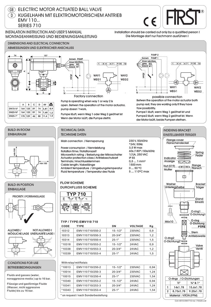
First
First 710 Series Installation instruction
Marco
Marco BLASTMASTER 153 Operator's manual

Vestamatic
Vestamatic Rolltec Plus 500 Installation and operating instructions


