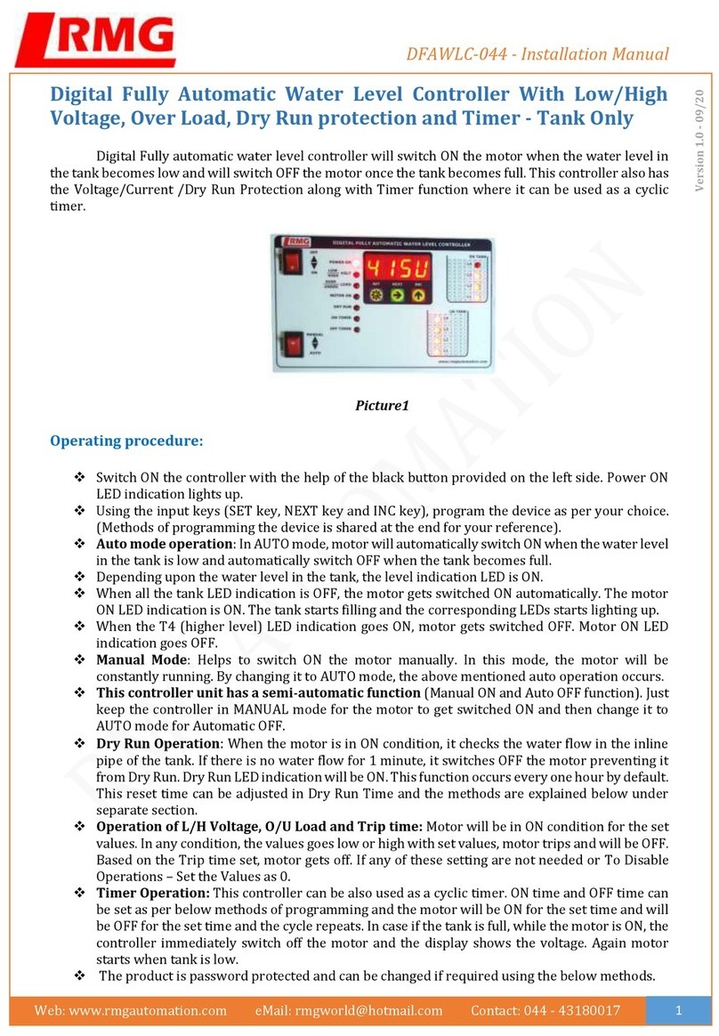
RMG 503 User manual

Operation and Maintenance,
Spare Parts
Serving the Gas Industry - WORLDWIDE
Gas Pressure Regulator
RMG 503
503.20
edition 01/2003
valid for gas pressure regulator RMG 503 from serial no. 0207 31622
and integrated SAV system RMG 711 from serial no. 9706 19948

Contents
page
1. General matters 3
1.1 Safety notices 3
2. gas pressure regulator 4
2.1 Special operating notices 4
2.1.1 Commissioning 4
2.1.2 De-commissioning 4
2.2 Special maintenance notices 4
2.2.1 Screw tightening moments 4
2.2.2 Lubricants 4
2.3. Spare parts
2.3.1 Spare part drawings 5, 6
2.3.2 Spare parts list 7
3. Integrated SAV system RMG 711
3.1 Special operating notices 9
3.2 Special maintenance notices 9
3.2.1 Switch gear 9
3.2.2 Main valve 10
3.2.3 Screw tightening moments 10
3.2.4 Lubricants 10
3.3 Spare parts
3.3.1 Spare part drawings 11, 12, 13
3.3.2 Spare parts list 14, 15
3.3.3 Spare part drawings accessories 16
3.3.4 Spare parts list accessories 17
4. Parts for maintenance purposes 18
503.20 p.02

503.20 p.03
Safety indications are indicated by the following key words or symbols
indication used for:
For the gas pressure regulator with integrated SAV RMG 503 the detailed product information 503.00 is
available containing
technical data, designs and measurements as well as design descriptions and operating
notices
.
The pertinent subassemblies are described in separate operating and maintenance instructions:
regulator RMG 630/640 630.20
filter RMG 905 905.20
control unit K 10a / K 11a 672.20
control unit K 16 / K 17 / K 18 670.20
push button valve RMG 910a 910.20
push button valve RMG 913a 913.20
1. General matters
1.1 Safety notices
The RMG publication "General operating instructions for gas pressure regulators and safety devices" provides
information on installation, commissioning, and operation, and contains notices on fault removal.
For planning and maintenance of gas pressure regulators the relevant national regulations must be observed:
Germany: DVGW worksheets G 600, G 459/II, G 490/I, G 491 and G 495
The time intervals for maintenance works on the pressure reducer RMG 218 (D118aV) depend largely on the
operating conditions and the composition of the gas. Therefore, no fixed maintenance intervals are being
prescribed. It is recommended to keep to the maintenance cycles stated in the DVGW worksheet G 495.
During maintenance all components must be cleaned and thoroughly checked for safety. A visual
check is required even if irregularities were found during operation or functional checks.
The check must cover seals and membranes in particular as well as any guiding components. Damaged
components must be renewed.
The item numbers mentioned in the maintenance notices correspond to those in the spare part drawing and
spare parts list.
It is recommended to keep the parts marked "W" in the spare part drawings and spare part lists in stock for
maintenance purposes. These parts are listed on a separate sheet.
!Danger
!Caution
Note
danger to persons
danger to equipment and the environment
Important additional information

Open the startup valve.
The startup valve is used to achieve safe pressure compensation at the throttle
diaphragm.
2.1.1 Commissioning
Close outlet gate valve
Fully release the setpoint springs of the regulator RMG 630/640 in the regualting stage
and the load limiting stage (regulator RMG 630 only) by turning the setpoint adjustment
screw anti-clockwise.
Apply inlet pressure slowly.
The startup valve must always be closed again.
Adjust the setpoint value in the load limiting stage at the regulator RMG 630 to
approx. 10 bar above pa.
Adjust the output pressure in small steps by turning the setpoint adjustment screw
clockwise until the desired value has been reached. The load limiting pressure at the
RMG 630 will rise automatically.
2.1.2. De-commissioning
Turn the setpoint adjustment screw of the regulating stage anti-clockwise
Slowly close the outlet gate valve
2.2 Special maintenance notices
Due to the maintenance-friendly design the maintenance of the gas pressure regulator is principally limited
to checking the throttle diaphragm. This must be checked for wear and swelling and where necessary be renewed.
Prior to dismantling all gas supplied chambers must be depressurised.
The throttle diaphragm (306) must be inserted into the main valve body without
distortion.
Foam rings (314 and 319) from nominal width DN 80/150 are to be renewed with
every maintenance.
2.2.1 Screw tightening torques M
A
in Nm
screw
item no. 25/50 50/100 80/150 100/200
318 160 160 240 240
nominal width DN
components lubricants RMG part no.
all O rings and
diaphram tensioning bead silicon grease 00 027 081 (tube 0.1 kg)
all fastening screws
and pipe screw connections assembly grease 00 028 267
For designs with noise reduction
the correct position of the relief plates
(328) must be observed ->
The groove of the relief plates
must face upwards
503.20 p.04
2. Gas pressure regulator
2.1 Special operating notices
•
•
•
Caution
!
Note!
•
•
•
Note!
•
•
•
2.2.2 Lubricants
•
•
•
!Danger

503.20 p.05
2.3.1 Spare part drawings
1
4
5
4
5
4
5
8
6
5
7
cross section A - B
GDR element
safety cut-off
unit (SAV)
AB

503.20 p.06
313
312
311
310
W
306
305
304
W 303
302
315
316
318
350
320
327
328
313
312
311
310
W 306
305
304
W 303
302
314
W
315
316
318
350
319 W
320
327
328
DN 25/50 and DN 50/100
DN 80/150 and DN 100/200
A
M
A
M
with noise reductionwithout noise reduction
M
Observe torques in table on page 4!
WParts should be kept in stock for maintenance.
A

item
no. description quant W material DN 25/50 DN 50/100 DN 80/150 DN 100/200
RMG stock no.
1 body, version "-":
1 PN 40 1 GS 10 024 470 10 024 520 10 024 620
1 PN 40 / ANSI 600 RF 1 GS 10 024 477 10 024 527 10 024 627
1 ANSI 300 RF 1 GS 10 024 473 10 024 523 10 024 623
1 ANSI 300 RF / ANSI 600 RF 1 GS 10 024 478 10 024 528 10 024 628
1 ANSI 300 RJ 1 GS 10 024 474 10 024 524 10 024 624
1 ANSI 600 RF 1 GS 10 024 475 10 024 525 10 024 625
1 ANSI 600 RJ 1 GS 10 024 476 10 024 526 10 024 626
1body, version "a"
1 PN 40 1 GS 10 027 670
1 PN 40 / ANSI 600 RF 1 GS 10 027 677
1 ANSI 300 RF 1 GS 10 027 673
1 ANSI 300 RF / ANSI 600 RF 1 GS 10 027 678
1 ANSI 300 RJ 1 GS 10 027 674
1 ANSI 600 RF 1 GS 10 027 675
1 ANSI 600 RJ 1 GS 10 027 676
4 screw plug 3 St 00 026 175 00 026 175 00 026 175 00 026 175
5sealing ring 6 LM 00 018 842 00 018 842
5 sealing ring 5 LM 00 018 842 00 018 842
6 connecting piece 1 St 00 030 074 00 030 074 00 030 111 00 030 111
7 connecting piece 1 St 00 030 111 00 030 111 00 030 023 00 030 023
8 connecting piece 1 St 00 030 074 00 030 074 00 030 074 00 030 074
503.20 p.07
2.3.2. spare parts list
WParts should be kept in stock for maintenance purposes
material identifications
St ... steel LM ... light alloy SSt ... foam
NSt ... rustproof steel Ms ... brass K ... plastic
FSt ... spring steel Cu ... copper KG ... rubbery plastic
NFSt ... rustproof spring steel Bz ... bronze KGT ... rubbery plastic with coating
GS ... steel cast GLM ... light alloy cast KV ... rubber-like plastic material (NBR)
GGG ... steel cast with spheroidal graphite GMs ... brass cast KT ... special plastic (NBR)
GZn ... zink cast AlBz ... aluminium bronze PGL ... plexiglass
GBz ... bronze cast

503.20 p.08
item
no. description quant W material DN 25/50 DN 50/100 DN 80/150 DN 100/200
RMG stock no.
302 flow divider 1 LM 10 011 137 10 011 137 10 011 237 10 011 237
303 o-ring 1 W KG 00 020 508 00 020 508 00 021 184 00 021 184
304 insert 1 St 10 023 551 10 023 551 10 023 631 10 023 631
305 slotted valve part 1 LM 10 023 550 10 023 550 10 023 630 10 023 630
306 diaphragm 1 W KG 10 011 140 10 011 140 10 011 240 10 011 240
310 connecting piece 1 St 00 030 023 00 030 023 00 030 023 00 030 023
311 spring 1 NFSt 10 011 149 10 011 149 10 011 249 10 011 249
312 diaphragm cover 1 St 10 021 590 10 021 620 10 021 653 10 021 685
313 pan head screw 1 St 00 010 021 00 010 021 00 010 003 00 010 003
314 foam disc 1 W SSt 10 023 593 10 023 633
315 pan head screw 1 St 00 008 176 00 008 176 00 010 393 00 010 393
316 diaphragm plate 1 LM 10 011 138 10 011 138 10 011 238 10 011 238
318 pan head screw 10 St 00 010 555 00 010 555
318 pan head screw 24 St 00 010 601 00 010 601
319 foam disc 1 W SSt 10 023 592 10 023 632
320 pan head screw 4 St 00 010 361 00 010 361 00 010 097 00 010 097
327 locking washer 4 St 00 014 118 00 014 118 00 014 123 00 014 123
328 release plate 1 LM 10 023 510 10 023 510 10 023 589 10 023 589
350 locking washer 10 St 00 014 116 00 014 116
350 locking washer 24 St 00 014 139 00 014 139 00 014 139 00 014 139

3.1 Special operating notices
opening the safety shut-off valve (SAV)
To open the SAV main valve insert handle (712) into the corresponding bore of the disk (734) and turn.
503.20 p.09
•
3. Integrated SAV system RMG 711
With control units K 10a or K 11a the SAV main valve can only be opened
if the control units have first been engaged.
To engage the control units K 10a and K 11a screw off lid, turn upside-down, and screw lid on to the
switching rod inside the control unit. Then pull the switch rod upward to the stop (see also 672.20).
The control units K 10a and K 11a are fitted with an underpressure shut-off device.
They can only be engaged if the pressure at the measuring point corresponds to the
operating pressure.
•
Test switching of the control units K 10a and K 11a
Test switching must only take place if the control units K 10a
and K 11a have been fitted to the switch casing (710), otherwise mechanical damage
could result.
3.2 Special maintenance notices
3.2.1 switch gear
Prior to removing the switch bearing (707) the pressure piece (768) must be removed from
the switch casing (710).
Please note during assembly of the switch bearing:
- an angled double edge of the switch bearing must point towards the pressure piece (768).
(see 3.3.1 SAV system cross section A-A)
- the sliding ring (721) must be positioned below the switch bearing.
•
•
Caution
!
Note!
Note!

503.20 p.10
•
3.2.2 Main valve
valve flap (753)
To visually check the o-ring of the valve flap (754) remove cover (747) and open SAV (engage).
When inserting a new lubricated o-ring (774) into the groove of the valve flap (753) the
o-ring should initially be pressed into the groove at 3 - 4 points spaced equally along the diameter.
Only then should the o-ring be pressed in completely.
After separating the valve flap from the valve flap lever (750) the locking nut (752) must be
tightened with the correct torque and must further be secured using the splint (773).
closing springs (731)
2 grooves for receiving the closing springs are forned into the spring casing (733). The grooves
are required for the different reception of the closing springs in the desings
"right hand operation"
or
"left hand operation"
.
When inserting the closing springs, they should intially be placed into the spring casing (733).
The correct orientation of the springs as shown in figure 1 and 2 should be observed.
The closing springs are properly pre-tensioned when all 4 fastening screws (732) can be fitted to the
casing (approx. half a turn of the spring casing). The valve flap must be in the "closed" position.
•
•
•
figure 2 closing spring inserting position for
"left hand" operation
figure 1 closing spring inserting position for
"right hand" operation
Torque MAin Nm
DN Schrauben-Pos.-Nr.
708 732 745 752 800
3.2.3 Screw tightening moments
MA
3.2.4 Lubricants
25/50 8 8 40 8 -
50/100 8 8 75 12 -
80/150 20 20 160 40 10
100/200 20 20 160 40 10
components lubricants RMG part no.
manual actuator thread (767) assembly paste 00 027 091
all o-rings, sliding sleeves,
sliding faces and switch elements silicone grease 00 027 081 (tube 0.1 kg)
all fastening screws
and pipe screw connections assembly grease 00 028 267

503.20 p.11
711
710
709
708
736
735
734
733
712
732
709
731
730
726
W
727 W
729
728
727 W
726
W
725
724
723
722
721
720
719
717
716
715
707
706
705
703
702
A
A
767
766
768
766
3.3.1. Spare part drawings
A
M
A
M
M
Observe torques in table on page 10!
WParts should be kept in stock for maintenance.
A
cross section A - A

503.20 p.12
750
754 W
747
745
746
A
M
A
M
745 746
lid design
DN 50/100 to DN 100/20 up to 09/96
safety cut-off unit
DN 25/50 to DN 100/200 version "-"
safety cut-off unit
DN 80/150 version "a"
774
775
753
774
801
774 750
774 750 729 800
773 752 803 802 748
W
A
M
DN 80/150 and DN 100/200 design from 06/97
DN 50/100 design from 01/99
DN 80/150 und DN 100/200
design from 01/2000
DN 25/50,
DN 50/100 design up to 1/99
773 752 747 748 746 745
W
A
M
W
754 753 774 750 729 800
A
M
M
Observe torques in table on page 10!
WParts should be kept in stock for maintenance.
A

503.20 p.13
812
811
810
813/814
810
813/814
815
DN 80/150 and 100/200
with push button valve RMG 910a
DN 25/ 50 and DN 50/100
with push button valve RMG 913a

item
no.!description!quant.!W!material!DN 25/50!DN 50/100!DN 100/200!DN 80/150
"a"
RMG stock no.
702 plug 1 K 00 026 550 00 026 550 00 026 550 00 026 550
703 disk 4 St 00 008 281 00 008 281 00 014 106 00 014 106
705 switch casing cover 1 LM 10 022 323 10 022 323 10 022 423 10 022 423
706 feather key 1 St 00 026 255 00 026 255 00 026 240 00 026 240
707 switch bearing 1 NSt 10 022 327 10 022 327 10 024 632 10 024 632
708 pan head screw 4 St 00 010 120 00 010 120 00 010 379 00 010 379
709 safety washer 8 FSt 00 014 111 00 014 111 00 014 112 00 014 112
710 switch casing, complete 1 GLM/K 10 022 326 10 022 326 10 022 426 10 022 426
711 bearing bush 1 Ms 10 022 318 10 022 318 10 024 638 10 027 688
712 handle, complete 1 NSt/K/KG 10 024 536 10 024 536 10 024 636 10 024 636
715 hexagonal screw 4 St 00 010 083 00 010 083 00 003 873 00 003 873
716 pan head screw 1 St 00 008 177 00 008 177 00 008 177 00 008 177
717 disk 1 LM 10 001 186 10 001 186 10 001 386 10 001 386
719 switch pin 2 St 00 027 646 00 027 646 00 027 301 00 027 301
720 arresting sleeve, complete 1 NSt/SF 10 022 332 10 022 332 10 022 432 10 022 432
721 sliding ring 1 KT 00 021 140 00 021 140 00 021 112 00 021 112
722 guiding sleeve 1 NSt 10 022 330 10 022 330 10 022 430 10 022 430
723 safety washer 3 FSt 00 014 118 00 014 118 00 014 111 00 014 111
724 pan head screw 3 St 00 010 561 00 010 561 00 010 150 00 010 150
725 retainer ring 1 FSt 00 019 110 00 019 110 00 019 112 00 019 112
726 o-ring 2 W KG 00 020 227 00 020 227 00 020 235 00 020 235
727 o-ring 2 W KG 00 021 142 00 021 142 00 020 607 00 020 607
728 valve flap shaft 1 NSt 10 022 317 10 022 317 10 024 637 10 027 687
729 feather key 1 St 00 026 256 00 026 256 10 024 646 10 024 646
730 bearing bush 1 Ms 10 022 319 10 022 319 10 022 369 10 022 369
731 spiral band spring 3 NSt 10 022 336 10 022 336
731 spiral band spring 4 NSt 10 022 436 10 022 436
732 pan head screw 4 St 00 010 549 00 010 549 00 010 428 00 010 428
733 spring casing, complete 1 GLM/K 10 024 535 10 024 535 10 024 635 10 024 635
734 disk, complete 1 LM/St 10 024 540 10 024 540 10 024 640 10 024 640
735 disk 1 St 00 014 082 00 014 082 00 014 137 00 014 137
736 pan head screw 1 St 00 010 618 00 010 618 00 008 177 00 008 177
745 pan head screw M10x30 10 St 00 010 400
745 pan head screw M12x60 12 St 00 010 625
745 up to autumn 1996 M12x70 12 St 00 010 594
745 pan head screw M16x80 12 St 00 010 626
745 up to autumn 1996 M 16x110 12 St 00 010 543
745 pan head screw M16x65 18 St 00 010 669
746 safety washer 12 FSt 00 014 114 00 014 116
746 safety washer 18 FSt 00 014 116
746 safety washer 10 FSt 00 014 113
503.20 p.14
3.3.2 spare parts list

!item
no.!description!quant.!W!material!DN 25/50!DN 50/100!DN 100/200!DN 80/150
"a"
RMG stock no.
747 lid 1 St 10 022 311 10 024 541 10 024 641 10 027 681
748 o-ring 1 W KG 00 020 247 00 020 427 00 020 573 00 021 361
750 valve flap lever 1 St 10 022 263 10 022 313 10 024 633 10 024 633
752 securing nut 1 St 00 013 199 00 013 200 00 013 202 00 013 202
753 valve plate, complete 1 Ms/NSt/St 10 022 262 10 022 312 10 022 407 10 022 407
754 o-ring 1 W KG 00 020 236 00 020 458 00 020 313 00 020 313
766 screw plug 2 St 00 026 175 00 026 175 00 026 175 00 026 175
767 manual release, complete 1 Al/FSt/NSt 10 022 340 10 022 340 10 022 440 10 022 440
768 pin with spring, complete 1 Ms/NSt 10 022 391 10 022 391 10 022 391 10 022 391
773 pin 1 St 00 015 000 00 015 000 00 015 007 00 015 007
774 O-Ring 1 KG 00 020 282 00 021 334 00 021 287 00 021 287
775 Druckfeder 1 FSt 10 018 394
800 hexagonal screw 2 St 10 024 648 10 024 648
801 grooved dowel pin 2 St 00 017 200 00 017 200 00 017 200
802 sealing ring 1 LM 00 018 694 00 018 694 00 018 694
803 screw plug 1 St 00 010 381 00 010 381 00 010 381
810 push button valve 1 10 005 200 10 005 200 89 100 210 89 100 210
811 screw connection 1 St 00 031 817 00 031 817
812 connecting piece 1 St 00 030 622 00 030 622
813 union nut 3 St 00 030 803 00 030 803
813 union nut 1 St 00 030 803 00 030 803
814 cutting ring 3 St 00 030 903 00 030 903
814 cutting ring 1 St 00 030 903 00 030 903
815 screw connection 1 St 00 031 207 00 031 207
503.20 p.15

503.20 p.16
3.3.3 Spare part drawing accessories
1012
1013
1000
1001
1002
1003
1004
1005
1006
1007
1008
1009
1010
1011
1014
1015
1017
1016
1020
1021
1022
electromagnet actuation during power supply electromagnet actuation during power failure
electrical indicator for "CLOSED" position

503.20 p.17
item
no. designation quant. W material part no.
1000 switch rod, optionally for:
1000 RMG 711 DN 25 and DN 50 1 NSt 10 022 568
1000 RMG 503 DN 25/50 and DN50/100 1 NSt 10 022 568
1000 RMG 530 DN 50/100 1 NSt 10 022 568
1000 RMG 711 DN 80 and DN 100 1 NSt 10 022 573
1000 RMG 503 and RMG 530 DN 80/150 and DN 100/200 1 NSt 10 022 573
1000 RMG 711 DN 150 1 NSt 10 022 578
1001 threaded bolt 1 St 00 008 486
1002 connection flange 1 LM 10 022 582
1003 guiding screw 1 NSt 10 001 811
1004 pressure spring 1 SF 10 001 183
1005 hexagonal nut 1 St 00 003 020
1006 adjustment nut 1 Ms 10 001 864
1007 bushing 1 LM 10 022 584
1008 O ring 1 KG 00 020 327
1009 magnet 1 00 024 436
1010 threaded bolt 4 NSt 10 022 585
1011 cover 1 LM 10 022 583
1012 packing ring 1 LM 00 018 706
1013 screw plug 1 St 00 026 523
1014 locking washer 4 SF 00 014 113
1015 hexagonal nut 4 St 00 005 692
1016 pressure spring 1 SF 00 028 067
1017 screw plug 1 Ms 10 022 586
1020 proximity switch 1 00 024 160
1021 cable box 1 00 024 099
1022 relay, optional:
1022 for 1 proximity switch (230V AC) 1 00 024 402
1022 for 2 proximity swirtches (230V AC) 1 00 024 403
3.3.4 Spare part list accessories

item
no. description quant. DN 25/50 DN 50/100 DN 100/200 DN 80/150
"a"
RMG part no.
303 o-ring 1 00 020 508 00 020 508 00 021 184 00 021 184
306 diaphragm 1 10 011 140 10 011 140 10 011 240 10 011 240
314 foam ring 1 10 023 593 10 023 633
319 foam ring 1 10 023 592 10 023 632
726 o-ring 2 00 020 227 00 020 227 00 020 235 00 020 235
727 o-ring 2 00 021 142 00 021 142 00 020 607 00 020 607
748 o-ring 1 00 020 247 00 020 427 00 020 573 00 021 361
754 o-ring 1 00 020 236 00 020 458 00 020 313 00 020 313
503.20 p.18
4. Parts for maintenance

503.20 p.19

The RMG Group of Companies on the internet: http://www.rmg.de
We supply you with products
for gas pressure regulation:
We reserve the right for technical changes
Serving the Gas Industry - WORLDWIDE
The other RMG Companies:
Bryan Donkin RMG Gas Controls Ltd.
Enterprise Drive, Holmewood, Chesterfield S42 5UZ, England
Telephone (++44) 1246 501-501 • Fax (++44) 1246 501-500
gas pressure regulating equipment, below ground gas control modules
RMG REGEL +MESSTECHNIK GMBH
Osterholzstrasse 45, D-34123 Kassel, Germany
Telephone (++49) 561 5007-0 • Fax (++49) 561 5007-107
gas pressure regulators and safety devices
RMG-GASELAN Regel + Meßtechnik GmbH
Julius-Pintsch-Ring 3, D-15517 Fürstenwalde, Germany
Telephone (++49) 3361 356-60 • Fax (++49) 3361 356-836
gas pressure regulating equipment, displacement meters, complete stations
RMG Messtechnik GmbH
Otto-Hahn-Strasse 5, D-35510 Butzbach, Germany
Telephone (++49) 6033 897-0 • Fax (++49) 6033 897-130
turbine meters, vortex meters, correctors, flow computers, odorizers
WÄGA Wärme-Gastechnik GmbH
Osterholzstrasse 45, D-34123 Kassel, Germany
Telephone (++49) 561 5007-0 • Fax (++49) 561 5007-207
design and assembly of gas pressure regulating and metering stations
Bryan Donkin RMG Co. of Canada Ltd.
50 Clarke Street South, Woodstock, Ontario N4S 7Y5, Canada
Telephone (++1) 519 5398531 • Fax (++1) 519 5373339
domestic regulators and safety devices
Karl Wieser GmbH
Anzinger Strasse 14, D-85560 Ebersberg, Germany
Telephone (++49) 8092 2097-0 • Fax (++49) 8092 2097-10
Heinrich-Lanz-Strasse 9, D-67259 Beindersheim/Pfalz, Germany
Telephone (++49) 6233 3762-0 • Fax (++49) 6233 3762-40
data logging, monitor systems, danger alarm systems
Betriebsstelle Beindersheim
This manual suits for next models
1
Table of contents
Other RMG Controllers manuals


