Caution: Switch off the main power while doing the Power Connection Steps.
Step 1: Wall mount the controller unit nearby motor pump switch/starter
location.
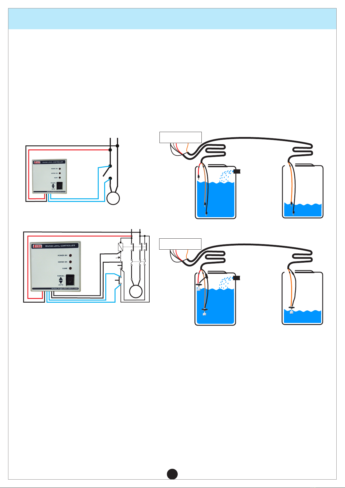
Step 2: Connect AC 230V to Red and Black wires of the controller respectively
(refer gure 1 and 2)
Step 3: For Switch or MCB, connect Blue pair wires to the switch/MCB of the
motor as shown in gure1.
Step 4: For starter, connect the blue pair wires to ON button of starter in parallel
and black wires to OFF button in series (refer to gure2)
4. INSTALLATION
2
PROCEDURE
Note: In case of doubts in installation, please call 044 - 43180017 or What's App
9940594413 from Monday to Saturday 10 am to 6 pm.
Step 5: Lay 4 core cable between controller and tank. Join one end of the 4 core
cable to sensor line of the controller as per colour coding. In tank side, Contact
type sensor connection: Take the sensors and cut them according to the levels of
tank and join them with the 4 core cable as per label coded. (Refer gure 3).
Magnetic oat sensor connections: These sensor has 2 wires. Use any one wire
in each sensor as common. Other wires left in each can be used for levels. Join
them with 4 core cable as per label coded.(Refer gure 4)
Step 6: Immerse the sensors inside the OHT & UGT as per Figure, and tape it.
This completes installation.
AC 230V
P N
MCB /
SWITCH
1Φ
MOTOR
Figure1: 1Φ SWITCH/MCB
Figure2: 1Φ Starter
Figure4: Magnetic oat sensor connection
Controller
water
Inlet
T1 (Brown)
T2 (Red)
(Black)CN
S1 (Orange)
(Black)CN
OHT
UGT
1Φ
motor
AC230V
P N
ON
NV
COIL
A1
A2
OFF
Remove
this wire
OLR
Figure3: contact type sensor connection
Controller
water
Inlet
T1 (Brown)
T2 (Red)
S1 (Orange)
OHT
UGT
Version 2.1-09/23