RMG AWFAWLC-044 User manual

RMG
RMG AUTOMATION
+91 9940594413
Advanced Wireless Long Range
Fully Automatic Water Level Controller
Model : AWFAWLC-044
www.rmgautomation.com
http://rmgautomation.com [email protected]
User Manual

1. INTRODUCTION
Water saving is Lifesaving. RMG Automation introduces an automated way
to save water. AWFAWLC-044 is a Radio Frequency Based Wireless Water Level
Controller with Indicators, in which it helps to ascertain the level of water in the
over head tank & sump as well as automatically control the motor pump. The
motor is switched ON automatically when the water level in the over head tank is
low, making sure water is present in the under ground tank (sump). The motor is
switched OFF automatically when the tank becomes full, or when the sump is
empty. It also has low voltage, high voltage and dry run indications.
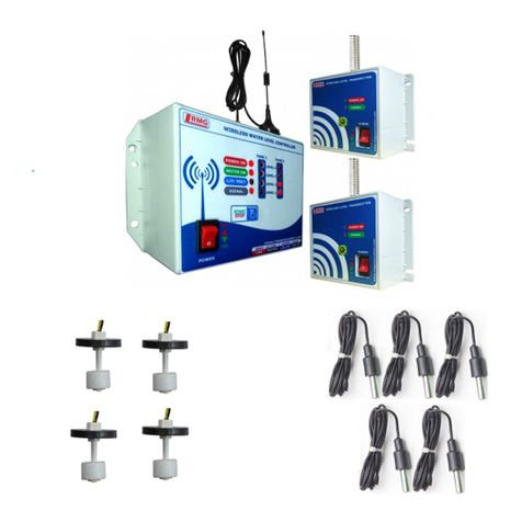
The maximum range that the product can work in line of site is 700 to 1000
meters. It has 2 outdoor transmitter units and 1 indoor controller unit. The
transmitter units are placed near the water tanks, whereas the controller unit is
placed near the motor pump control switch/starter location. This product is
suitable for underground to over head tank setup.
2. DESCRIPTION
2.1 CONTROLLER / RECEIVER
ŸPower ON/OFF switch – used to switch ON / OFF the device.
ŸPower ON LED – shows ON/OFF status of device.
ŸON button – Used for manual motor ON. And for pairing the controller with
transmitter.
ŸOFF button – Used for manual motor OFF. And to enable/disable dry run option.
ŸRF SIGNAL LED – shows the signal status. When it blinks the communication
between transmitter & controller is good. When it is continuously glowing, it
means there is no communication.
ŸL/H VOLT LED - shows high/low voltage indication. If the LED glows motor will
not run and protect from voltage uctuations.
ŸDRY RUN LED - It indicates the dry run of motor and glows when there is no
water in the inlet of the tank for 90 seconds.
ŸMOTOR ON LED - It indicates the motor ON/OFF status.
ŸLevel Indicator LEDs - These LEDs shows the water levels of the tank and
sump. There are 4 level indications for both, each with 25%,50%,75% and
2.2 TRANSMITTER
ŸRF signal LED – It blinks once when the battery is inserted. It also blinks
whenever the controller device asks it for the water level.
ŸCharging LED – glows when battery is charging (red LED)
ŸCharging complete LED– glows when battery is fully charged (blue LED)
ŸSolar panel – 6V/100mA solar panel for charging battery.
ŸLi-ion battery – 3.7V rechargeable battery.
3. TOOLS REQUIRED
ŸDrill gun, Simple hammer
ŸWooden gattas
ŸScrews for mounting units on wall
ŸLine tester
ŸWire stripper
Ÿ1.5Sq.mm Wire for power &
control wiring
ŸInsulation tape, Cable (6 core)
1

Caution: Switch off the main power while doing the Power Connection.
Step 1: Wall mount the Controller unit nearby motor pump switch/starter
location. The location chosen should be near the window or in open space to ensure
good signal strength.
Step 2: As per your model purchased, Connect AC supply (AC 230/440V) to 1st
and 2nd terminal of the controller as shown in the gure1 or gure2.
Step 3: For switch or MCB, connect 3rd and 4th terminal of device in parallel to
the switch as shown in gure1.
4. INSTALLATION
PROCEDURE
Step 4: For starter type connection refer to gure2 & Figure3. In case of other
types of connections or doubt what's app to 9940594413 or call 044-43180017
Step 5: Turn ON the controller. Now, Power ON LED will glow. Unscrew the top
panel of transmitter. There is a battery holder inside it. Put the given Li-ion battery
inside the case, according to polarity. RF Signal LED blinks once.
Step 6: Take the transmitter near the overhead / underground tank. To check the
communication between transmitter and controller, Press the push button inside
transmitter for more than 16 seconds. RF Signal LED blinks two times with 5
seconds interval. This ensures the perfect communication between them. .
Step 7: Now power off the controller unit. Contact type sensor connection: Take
the sensors and cut them according to the levels of the tank and join them with
the sensors lines of transmitter as per color coding. (Refer gure4). Magnetic
oat sensor connection: These sensors has 2 wires. Use any one wire in each
sensor as common. Other wire left in each can be used for levels.
Step 8: Immerse the sensors in the water tank and place at 25%, 50%, 75%,
100% levels. Dry run sensor should be xed in the inlet of the tank. Join black &
green wire of transmitter to this sensor. No dry run connection for UG tank.
Step 9: Close the top panel of the transmitter using the screws. Place the solar
panel facing sun light using the double side tape.
This completes the installation 2
water
Inlet
(Brown)25%
(Red)50%
( )75%Orange
( )100%Yellow
(Black)CN
(Green)
DryRun
Figure1: 1Φ SWITCH/MCB
Figure3: 1Φ Starter
Figure4:
Trasnmitter
Figure2: 3Φ Starter
3Φ
MOTOR
R Y B
ON
OLR
NV
COIL
A1
A2
OFF
Remove
this wire
1Φ
MOTOR
AC230V
P N
ON
OLR
NV
COIL
A1
A2
OFF
Remove
this wire
AC 230V
P N
MCB /
SWITCH
1Φ
MOTOR

5. OPERATING PROCEDURE
ŸPower ON the controller unit.
ŸDepending upon the water level in tanks, the level indication LEDs are ON.
ŸIf the water level goes low, controller automatically TURNS ON the motor (only
when sump has water), during this time MOTOR ON LED glows. When the tank
becomes full, controller unit automatically TURNS OFF the motor. Motor will get
off even when sump level is low.
S.No
Error
Solutions
1
No
communicati
on between
controller
and
transmitter
a. Check whether any obstacles are there in between
transmitter and receiver units like large trees, buildings
etc.(Repeater can be added if necessary).
b. Check the battery in transmitter whether it is
connected correctly without any loose contacts.
c. Check whether the battery is completely drained out, If
so, charge the battery using the USB port in it for instant
charging.
2
Dry run is
not working
a. Check whether dry run option is enabled in controller
unit. Keep the controller in pairing mode. Press ON
button and without removing the nger turn ON the
controller. If DRY RUN LED is ON, the dry run option is
enabled. If DRY RUN LED is in OFF state, the dry run is
disabled.
b. Check the dry run connection on the tank whether it
has any loose contacts. If so correct it.
3
Tank level
indicator
LEDs are off
If one or all the level indicator LEDs are not glowing,
a. Check common sensor connection is correctly made. If
any loose contacts correct it.
b. Check all the sensor connections if they are having any
loose contacts. Also, check if the cable lines are intact.
6. TROUBLESHOOTING METHODS
3
ŸPAIRING PROCEDURE: The units are generally paired and given. In case of
any trouble at the time of installation, users can pair the units once again.
ŸPress the Green ON button and do not take the nger out while doing this.
Turn ON the controller. All the tank level LEDs will blink. It means the device
is ready for pairing.
ŸIn transmitter, there is a Push button inside it. By pressing the push button
and without taking out the nger from it, insert the battery into the battery
holder. Now the RF Signal LED inside transmitter blinks once and all the
tank level LEDs goes off in the controller unit. Thus pairing is completed.
ŸDRY RUN ENABLE/DISABLE: Set the controller in pairing mode. Use the
OFF button to enable or disable the dry run function which is denoted with
Dry Run LED indication.
Table of contents
Other RMG Controllers manuals
