RMS Pelvic Belt Series Instruction Manual

USER / CARER INFORMATION PLEASE READ PRIOR TO USE.
Straps or Harnesses should be the last item to be released or removed before the User leaves
the wheelchair and the first things to be secured after entering.
The Pelvic Belt length may require adjustment periodically, to allow for User growth, changes
to User’s disability or changes in seasonal clothing. Adjustments to belt or strap lengths can
be made at the main buckles, with further adjustment available at the Tri-slot mounting plates,
located at each anchored end of the Belt.
PRODUCT CLEANING
All RMS Pelvic Belts with Plastic Centre Buckles, are Machine Washable.
Water ingress to the metal buckle can be avoided by holding the Belt by the Buckle in one
hand whilst lightly sponging with warm soapy water, with a little disinfectant added, with the
other hand.
NOTE: Both types of RMS Belts can also be cleaned using car type upholstery cleaner.
Again, avoid fluid ingress, by holding or covering the Metal Buckles whilst cleaning.
Ensure the Belt is completely dry before returning to service.
To ensure this device remains safe, and reliable throughout its period of service, RMS
recommends it be inspected for wear, damage and security of components at 3 monthly intervals.
(For heavier Users the period between inspections should be reduced accordingly). Any worn or
damaged Belts should be replaced as soon as possible with original equipment parts, available
from RMS Ltd.
For further information regarding this or any other products in the RMS range, please contact the
RMS Technical Help-line on 01795 477280.
MACHINE
WASHABLE
60°c
Plastic Centre Buckle
RMS Pelvic Belts with Metal Centre Buckle MUST
NOT be Machine Washed, as water ingress to the Buckle
mechanism could cause premature rusting and subsequent
mal-function at a later date. They may however, be Hand
Washed with CAUTION, ensuring water does not enter the
Metal Centre Buckle area.
HAND
WASH
ONLY
Metal Centre Buckle
Feb 2018
The RMS Pelvic Belt Range
FITTING GUIDELINES
(The Batch Number and Installation date of this product should be recorded after fitting)
WARNINGS:
All RMS Pelvic Belts are designed for postural positioning and individual security only,
not as a method of restraint.
UNDER NO CIRCUMSTANCES should this Pelvic Belt be used as the sole method of
securing the User in a wheelchair, during transportation in a motor vehicle.
It is recommended that this Pelvic Belt be installed by a suitably qualified person,
giving the necessary consideration to positioning, direction of pull, strap routing and
correct adjustment.
Achieving the correct tension is extremely important as too tight, can result in
unnecessary discomfort or distress to the User, whereas too loose, could allow the
User to slide under the Belt into a seriously dangerous position.
A slack Pelvic Belt may also create a hazard by rolling upwards or downwards enabling
the buckle release pad to come into contact with a rigid piece of clothing i.e. a large
coat button or belt buckle, which in turn, could release the buckle of the Pelvic Belt .
FITTING
RMS Pelvic Belts are supplied with optional methods of attachment to a wheelchair.
Initially, the installer will need to establish the most suitable positions for the Pelvic Belt to be
attached, according to the User’s disability, type of Pelvic Belt and type of wheelchair. It is
recommended that this is carried out with the User seated in the wheelchair and the Pelvic
Belt laid around the User in the intended position.
The Pelvic Belt should be attached either by utilising suitable existing frame screws, or by use
of the RMS Universal Mounting Clamps, MC123 included with this kit (see Fig1). These
clamps enable the Pelvic Belt to be attached to round frame tubes of 19, 22 or 25mm
Diameter without drilling. Where the preference is to use suitable existing frame screws, the
User should be removed from wheelchair before slackening or removing any screws,
(Minimum screw dia. 5mm).
Fig.1 Fig.2 Fig.3
MC 123 Tri-slot Mounting Plate Enclosed Mounting Plate
RMS Ltd, Thompson House
Unit 10, Styles Close, Sittingbourne
Kent, ME10 3BF
tel: 01795 477280 fax: 01795229692
Email: [email protected]
www.ineedawheelchair.co.uk
To attach the Pelvic Belt using RMS frame clamps MC123 (Fig.1), install the clamps, together
with any appropriate size spacer shim, onto the frame tubes in the most suitable position to
create a 45° directional line over the pelvis (see Diagrams below). NOTE: ensure the locating
lugs on any spacer shims engage into the slots in the Clamp. MC123 Clamps are suitable for
use with both Tri-slot and Cam Lock Mounting Plates.
When using Tri-slot Mounting Plate method of
attachment, Figs.2 & 4, install a Tri-Plate onto each
free end of the Belt by threading the end of the webbing
through the slots as shown in Fig.4. (Do Not adjust at
this stage). Insert the clamping screw through the Tri-
slot Mounting Plates (from the side which is marked
CE , RMS and is recessed to take the screw head) and
screw into the M6 captive nut in each Clamp. Tighten in
line with the direction of pull. Screws should be
tightened sufficient to prevent any movement of the
Clamps, although this may allow the Tri-Plates to
revolve around the screws, with some resistance.
Adjust belt lengths as required and pull webbing tight against Tri-Plates.
When using the enclosed Cam Lock Mounting Plate
method of attachment, Figs.3 & 5, install a Mounting
Plate onto each free end of the Belt by raising the
Cam Buckle cover, threading the end of the webbing
through the Cam Buckle side of the Mounting Plate,
around the bridging bar, then back through Cam
Buckle as Fig.5. (Do Not adjust at this stage).
With the Cam Buckle cover raised, insert clamping
screw, with washer through each Cam Lock Mounting
Plate and screw into the M6 captive nut in each
Clamp. Tighten in line with the direction of pull.
Tighten screws sufficient to prevent any movement of
the Clamps , although this may allow the Cam Lock Mounting to revolve around the screws, with
some resistance. Adjust belt lengths as required and close Cam Lock Mounting cover to secure.
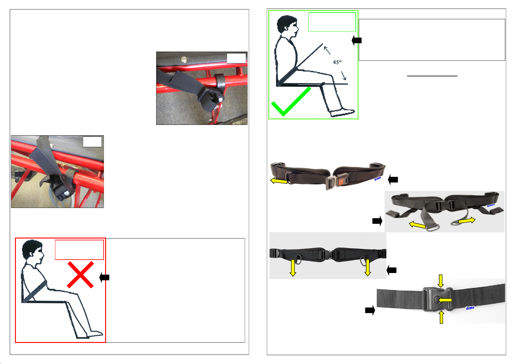
USER POSITIONING
[cont]
Belt positioned above the Pelvis against soft
tissue area of Lower Abdomen.
The Hips are forward in the seat giving a
reclined posture.
The Belt will not generally stop the person
slipping down in the seat.
Incorrect position can be caused by:-
The occupant being unable to attain a 90°
sitting position.
The occupant slipping down in the seat due
to inappropriate fitting / adjustment or the
belt being held away from the occupant by a
part of the seat system (e.g. belt over top of
armrests or over hip / thoracic supports.
Incorrect
Belt Position
Fig.4
Fig.5
USER POSITIONING [cont]
ADJUSTMENTS
As the positioning and tension of a Pelvic Belt is
extremely important to achieve its intended purpose, care
should be taken to ensure that all straps are attached with
the correct direction of pull, appropriately adjusted with any
Comfort Pads suitably positioned.
Incorrect tension, i.e. too tight, can result in unnecessary
discomfort or distress to the User, whereas too loose, can
allow the belt to roll upwards or downwards thus not achieving its intended purpose. This
could also allow the buckle release catch to come into contact with a more rigid piece of
clothing, i.e. a large button or belt buckle, which in turn could inadvertently operate the
release catch on the Belt. Should the User show continued signs of discomfort or distress due
to the Pelvic Belt a suitably qualified person should be consulted immediately.
For “Single Pull” type belts, adjustment is
made after connecting the main buckle, by
pulling the strap fitted with a “D” ring to the
side of the main buckle, outwards away
from the centre.
With “Dual Pull” type belts, adjustment is
made, after connecting the main buckle, by
equally pulling, the “D” ring straps located at
either side of the main buckle, outwards
away from the centre.
For “Rear Pull” type belts, adjustment is
made after connecting the main buckle, by
pulling the “D” ring straps located towards the
rear of the Comfort Pads, in a forward direction,
thus creating a rearward pull on the Pelvic
Belt.
Due to the nature of the use of this style
of belt, the “Twin Lock” has no length
adjustment available at the Main Buckle.
Any adjustments to the belt length,
can be made at each fixed end of the
belt via the Tri-slot mounting plates.
NOTE: The Pelvic Belt length may require adjustment periodically to allow for User growth,
changes in the User’s disability or changes in seasonal clothing. Adjustments to the belt length
can be made at the main buckle, with further adjustment available at each fixed end of the Belt
via the Tri-slot mounting plates or Enclosed Cam Lock mounting plates.
Occupant in, or near, 90° sitting position.
Posture / safety belt fixed near to corner of
seat base, with a snug fit over the Pelvis at
45°.
Correct
Belt Position
Popular Safety Equipment manuals by other brands

Lanex
Lanex PB-20 instruction manual

SKYLOTEC
SKYLOTEC ANCHOR ROPES Instructions for use

Besto
Besto Buoyancy Aid 50N Instructions for use

TEUFELBERGER
TEUFELBERGER NODUS Manufacturer's information and instructions for use

Troy Lee Designs
Troy Lee Designs Tbone Product owners manual

Innova
Innova Xtirpa Instruction and safety manual

bolle SAFETY
bolle SAFETY B810 quick start guide

SHENZHEN FANHAI SANJIANG ELECTRONICS
SHENZHEN FANHAI SANJIANG ELECTRONICS A9060T instruction manual

Hiltron security
Hiltron security POWER8E Installation and use manual

Salewa
Salewa MTN SPIKE user manual

Hatco
Hatco B-950P installation guide

Sitec
Sitec TX MATIC operating manual


