RNA FP 15 E User manual

Installation instructions
relating to
Belt conveyors
FP 15 E
FP 15 D

Rhein-Nadel Automation GmbH 2
VT-BA-FP15-EN_2018 / 13.11.2018 SJ
Table of Contents
1. Technical data........................................................................................................................ 4
1.1. Table................................................................................................................................... 4
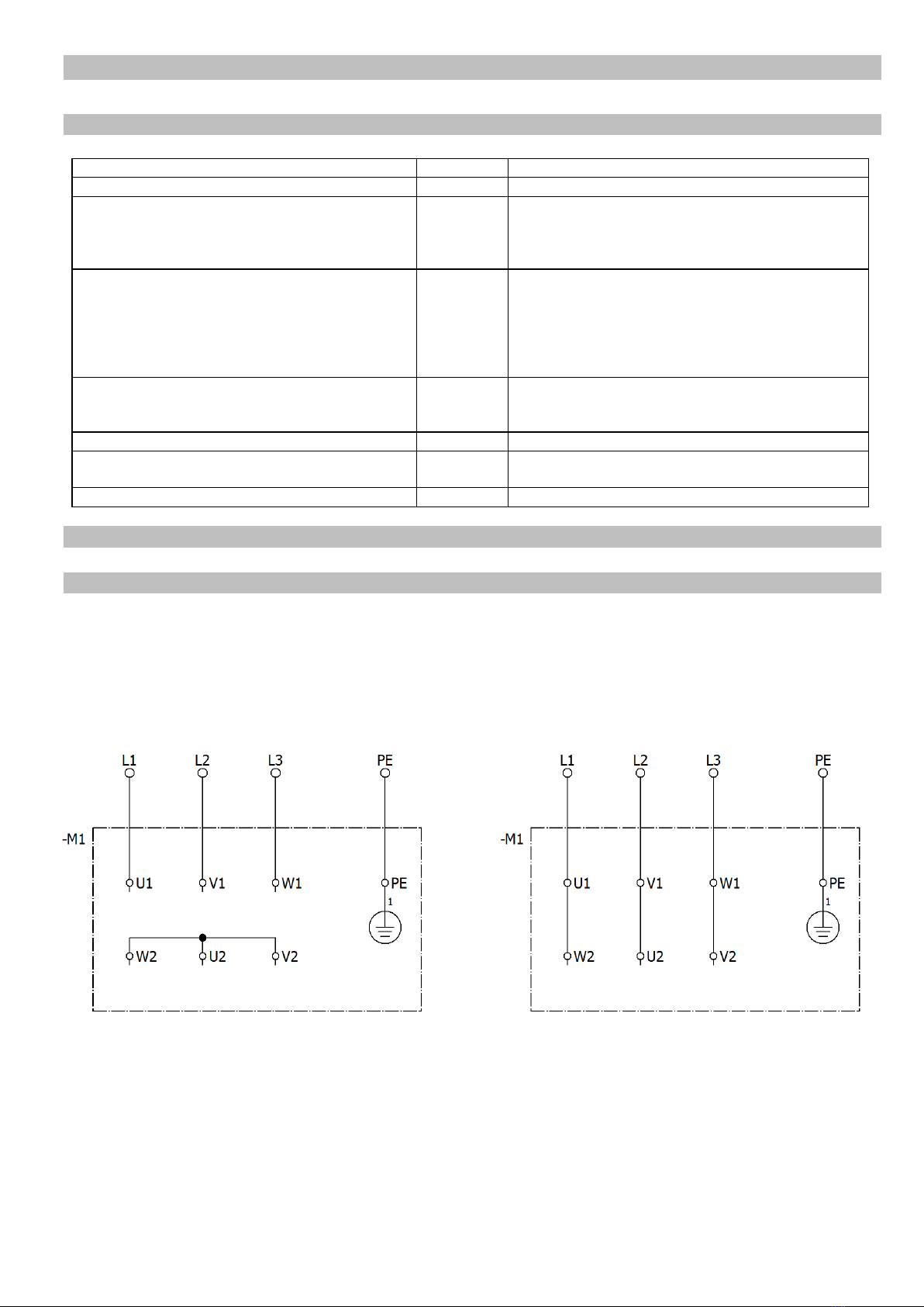
1.2. Motor connection diagrams................................................................................................. 4
1.2.1. Dunker / Rotek three-phase motor ............................................................................... 4
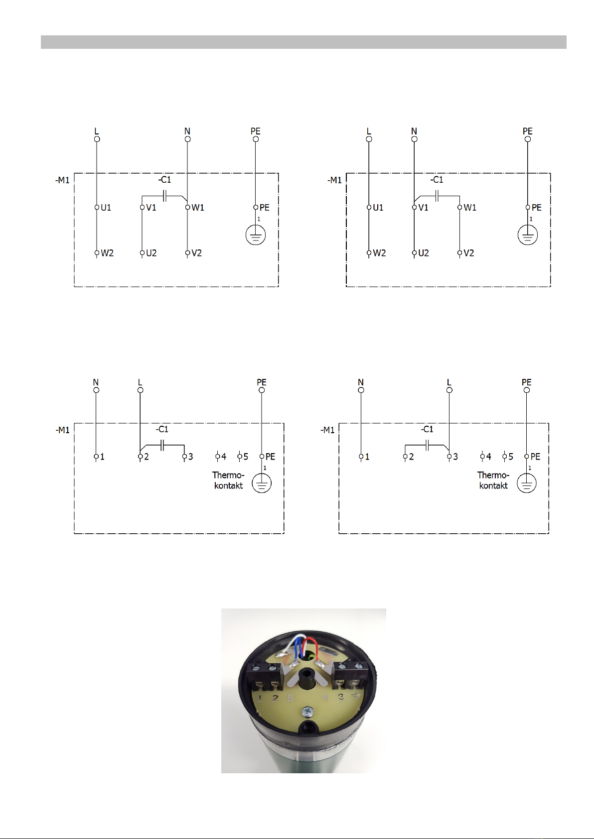
1.2.2. Dunker / Rotek AC motor ............................................................................................. 6
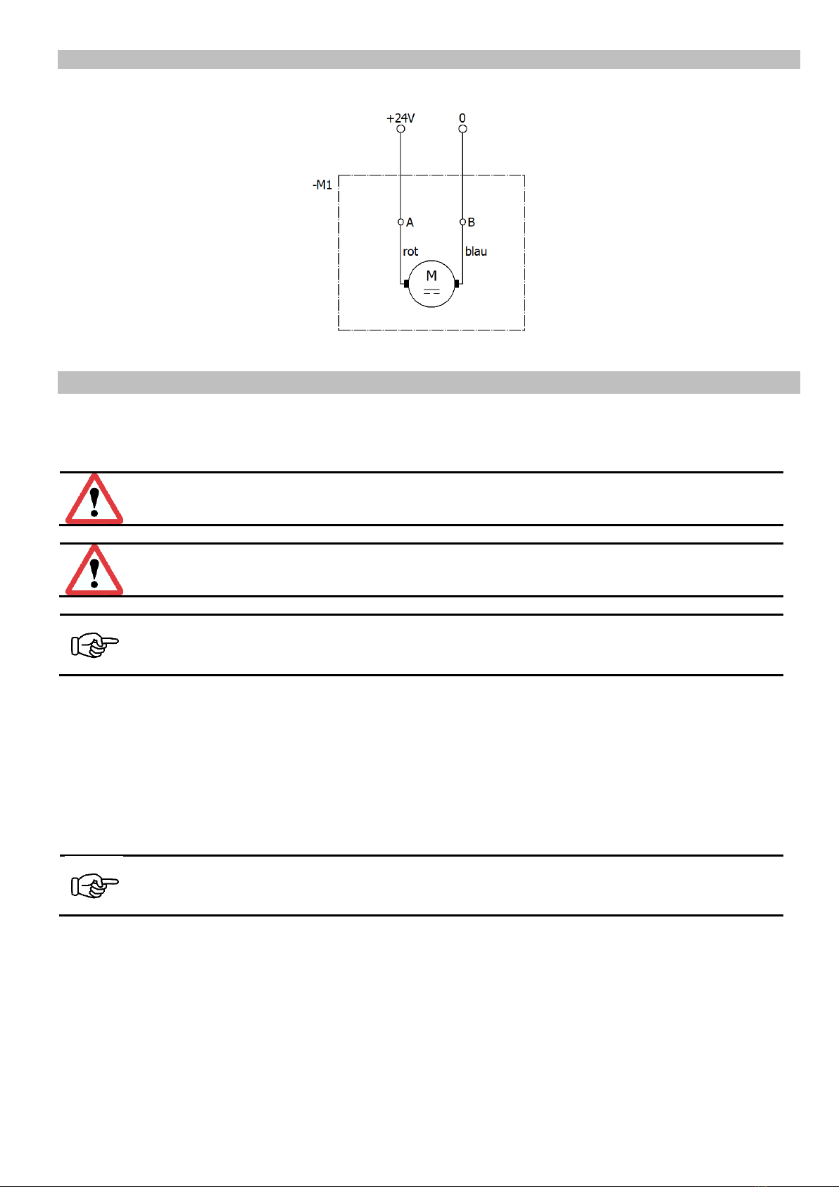
1.2.3. Engel DC motor............................................................................................................ 7
2. Safety directives..................................................................................................................... 7
2.1. Applicable directives and standards.................................................................................... 9
3. Design and functional description of belt conveyors .............................................................. 9
4. Shipment and installation ..................................................................................................... 10
4.1. Shipment........................................................................................................................... 10
4.2. Connecting the motor........................................................................................................ 10
4.3. Installation on supports ..................................................................................................... 10
5. Commissioning..................................................................................................................... 11
6. Maintenance......................................................................................................................... 12
6.1. Belt.................................................................................................................................... 12
6.2. Motor................................................................................................................................. 12
6.3. Gearbox ............................................................................................................................ 12
6.4. Return, drive and supporting rollers .................................................................................. 13
6.5. Environmental effects ....................................................................................................... 13
7. Spare parts and customer service........................................................................................ 13

Rhein-Nadel Automation GmbH 3
VT-BA-FP15-EN_2018 / 13.11.2018 SJ
Declaration of Incorporation
according to Machinery Directive 2006/42/EC
We hereby declare that our product is intended to be incorporated into or assembled with other machinery to constitute one machine in terms of the
Directive indicated above (or parts thereof) and that it must not be put into operation until the relevant machinery into which it is to beincorporated
has been declared to be in conformity with the EC Machinery Directive.
Applied harmonised standards:
DIN EN 60204 T1, DIN EN ISO 12100-2011-03, DIN EN 619, DIN EN 620
DIN EN 1050
Remarks:
This product has been manufactured in accordance with the Low-Voltage Directive 2014/35/EU.
We assume that our product will be incorporated into a stationary machine.
Rhein-Nadel Automation GmbH
Managing Director
Jack Grevenstein

Rhein-Nadel Automation GmbH 4
VT-BA-FP15-EN_2018 / 13.11.2018 SJ
1. Technical data
1.1. Table
Belt lengths = shaft center distance
(mm)
200 to 2,000
Belt widths
(mm)
10, 20, 30, 40 and toroidal driving cords Ø3
Conveyor load
(N)
max. 100 total load
depending on motor, belt width and mode of
operation (conveyance or accumulation) the total
load may be much higher
Belt speed +/- 20% constant
+/- 10 % variable
(m/min.)
Constant (three-phase 230/400V 50Hz):
5, 9, 15, 21, 37
Constant (AC 230V 50Hz):
5, 9, 15, 21
Variable: (direct current 24 VDC)
2-13, 3-17, 4-26, 5-30, 6-40
Adjusting range (clearance) for FP15D
mm
0-25 adjustable
20-55 adjustable
50-80 adjustable
Current input
see rating plate
Roller diameter
(mm)
return rollers 30
knife edges 8
Tensioning station
forms part of motor baseplate
1.2. Motor connection diagrams
1.2.1. Dunker / Rotek three-phase motor
Connection of Dunker three-phase motors
For reversing the sense of rotation change two phases of the supply line
Connection to three-phase supply
Low voltage
3x230V
Connection to three-phase supply
High voltage
3x400V

Rhein-Nadel Automation GmbH 5
VT-BA-FP15-EN_2018 / 13.11.2018 SJ
Connection of Rotek three-phase motors
For reversing the sense of rotation change two phases of the supply line
Fig. 1 Fig. 2 Fig. 3 Fig. 4
The protective earth conductor PE is to be connected by user.
A thermal contact is connected to terminals 4 and 5 (Do not connect supply voltage here).
For changing the connection from star (3x400V) to delta (3x230V) remove the (star point) terminal (Fig. 2).
This terminal (Fig. 2) is not needed for delta connection and should be kept in a safe place.
Connect the free cables in the top triple terminal. Colours (Fig. 3) from left to right: red-blue-white.
Fig. 4 is a view on the triple terminal from the other side showing the colours from right to left: red-blue-white.
The Rotek three-phase motor cannot be changed to an AC motor!
For operation with a variable-frequency drive unit the frequency range should be from 12 to 60 Hz for the Rotek motor
and from 17 to 85 Hz for the Dunker motor.
Motors list
i
n
motor
v
m/min.
VFD mode
v min.
VFD mode
v max.
Motor current
max. mA (50/60Hz)
Dunker
DR62.0X80-4/SG80, i=5:1
5
1200
39.8
13.5
67.7
3~400V: 190/190
3~230V: 290/290
DR62.0X80-4/SG80, i=10:1
10
1200
19.9
6.8
33.9
DR62.0X80-4/SG80, i=15:1
15
1200
13.3
4.5
22.6
DR62.0X80-4/SG80, i=24:1
24
1200
8.3
2.8
14.1
DR62.0X80-4/SG80, i=38:1
38
1200
5.2
1.8
8.9
Rotek
DS ROSYNC 84 SN18H 7:1
7
1500
35.6
8.5
42.7
3~400V: 200/175
3~230V: 350/300
DS ROSYNC 84 SN18H 12:1
12
1500
20.8
5.0
24.9
DS ROSYNC 84 SN18H 15:1
15
1500
16.6
4.0
19.9
DS ROSYNC 84 SN18H 24:1
24
1500
10.4
2.5
12.5
DS ROSYNC 84 SN18H 38:1
38
1500
6.6
1.6
7.9
Connection to three-phase supply
High voltage
3x400V
Connection to three-phase supply
Low voltage
3x230V

Rhein-Nadel Automation GmbH 6
VT-BA-FP15-EN_2018 / 13.11.2018 SJ
1.2.2. Dunker / Rotek AC motor
Connection of Dunker AC motors
Connection of Rotek three-phase motors
The protective earth conductor PE is to be connected by user.
The capacitor capacitance is 2.4 µF for Rotek (use genuine capacitors only) and 3 to 5 µF for Dunker.
The Rotek AC motor (Fig. 5) cannot be changed to a three-phase motor.
Fig. 5
Connection to a.c. supply
1x230V
CW rotation
Connection to a.c. supply
1x230V
CCW rotation
Connection to a.c. supply
1x230V
CW rotation
Connection to a.c. supply
1x230V
CCW rotation

Rhein-Nadel Automation GmbH 7
VT-BA-FP15-EN_2018 / 13.11.2018 SJ
1.2.3. Engel DC motor
Connection of Engel DC motors
To reverse the sense of rotation change the feeder connection.
2. Safety directives
We have taken great care in design and manufacture of our conveyors in order to ensure smooth and safe operation.
You, too, can make an important contribution towards safety at work. We therefore ask you to read these brief
operating instructions completely prior to commissioning the system. Observe the safety directives at all times!
Attention
This warning sign indicates safety directives. Non-observance of such warnings may cause serious
injury or even death!
Caution
This warning sign indicates safety directives. Non-observance of this warning may cause minor injury or
material damage.
Notice
This hand indicates useful tips for operation of the conveyors.
Make sure that all persons working with or at the equipment also read the following safety directives carefully and
follow them!
These Operating Instructions only apply to the equipment types indicated on the cover page.
They must be available at all times at the place of installation of the conveyor.
If the conveyor is to be used in a humid or wet environment (wet area) make sure that the required degree of
protection is provided.
Notice
For comprehensive information on the full range of control devices please refer to the 'Control Units'
operating instructions.
Any commissioning, retooling, maintenance and repair work shall be carried out by qualified and authorized personnel
only (see also 'Operator's duties' in this section).
For installation, maintenance and repair work all poles of the power supply must be disconnected from the conveyor in
compliance with VDE provisions.
Any work on the electrical equipment shall be carried out exclusively by a professional electrician, or by instructed
persons working under the supervision of a professional electrician, according to electrotechnical rules.

Rhein-Nadel Automation GmbH 8
VT-BA-FP15-EN_2018 / 13.11.2018 SJ
Attention
Risk of injury and electric shock hazard!
•The equipment user and operators shall ensure that only authorized personnel works at the conveyor.
•Any changes that have occurred on the feeding system affecting safety shall immediately be reported to the
user.
•Operate the conveyor in perfect condition only.
•Use the belt conveyor only for its intended use.
•Observe the accident prevention provisions VBG 10 for continuous conveyors and VBG 4 for electrical
equipment and components"
Machine hazards
•If the belt conveyor comes into contact with moisture or liquids there is risk of electric shock.
•Make sure that protective earthing of the power supply system is in perfect condition.
•Never operate the conveyor without guards and cover panels in place!
Intended use
The intended use of the belt conveyors is the feeding of parts.
The shortest side of such parts must be at least 5 mm long. Special versions or accessory equipment are available to
modify the belt conveyors for use with parts having smaller side lengths (> 0.5 mm). If necessary, please contact the
manufacturer.
Caution
Smaller parts may get under the belt and cause damage or failure of the belt conveyor.
Parts handled with standard belts must be dry, clean and without sharp edges.
Caution
If the parts to be handled are that may fall over, roll or slide, sufficiently dimensioned side guards must
be selected from our range of accessories.
The belt conveyors are designed for horizontal transport at maximum loading. A slight inclination of the conveyor is
possible in some cases. Please consult the manufacturer to determine what is possible for your specific application!
For permitted belt loading see Technical Data in section 1.
Noise emission
The constant sound pressure level is 70 dB(A) max. Specific part handling applications or belt designs may result in
higher noise levels. For such exceptional cases noise abatement options are available from manufacturer.
Equipment user's duties
Commissioning, retooling, maintenance and repair work shall be performed by qualified and authorized personnel
only.
We distinguish between four qualification levels:
Qualified personnel
refers to persons who are familiar with installation, start-up and operation of the conveyor. Their qualifications are
appropriate for their activities.

Rhein-Nadel Automation GmbH 9
VT-BA-FP15-EN_2018 / 13.11.2018 SJ
Authorized personnel
refers to qualified personnel that has been assigned a clearly defined task by the user of the belt conveyor.
Qualified electrical worker
According to IEC 364 and DIN VDE 0105 Part 1, the term 'qualified electrical worker' refers to persons who, through
their professional training, know-how and experience and through their knowledge of applicable standards are able to
assess the work assigned to them and to recognize potential hazards.
Instructed person
According to IEC 364 and DIN VDE 0105 Part 1, the term 'instructed person' refers to persons who have been
instructed in the tasks assigned to them by a qualified electrical worker. These persons have also been briefed on
potential dangers resulting from inappropriate behaviour, and on the requisite guards and precautions to be
used/taken.
2.1. Applicable directives and standards
The belt conveyor has been manufactured in accordance with the following directives:
•EC Machinery Directive 2006/42/EC
•EC Low-Voltage Directive 2014/35/EU
•Electromagnetic Compatibility Directive 2014/30/EU
We assume that our product will be incorporated into a stationary machine. The requirements of the EMC Directive
must be satisfied by the user.
The applicable standards are specified in the Declaration of Incorporation.
3. Design and functional description of belt conveyors
The belt conveyors are made up of a special grooved aluminium profile. For belt drive a number of motors are
available for constant and variable speed. The motor may be arranged at the entry or exit end of the belt or in the
middle. Control of the belt conveyor is effected, depending on motor type, by motor protection breaker or electronic
control devices.
Notice
For information on the control devices please refer to the separate 'Control Units' operating instructions.
Fig. 1: Belt conveyor layout

Rhein-Nadel Automation GmbH 10
VT-BA-FP15-EN_2018 / 13.11.2018 SJ
4. Shipment and installation
4.1. Shipment
Shipment ex works
The belt conveyors are delivered ex works in cardboard or box packaging.
Handling on site
The belt conveyor weight depends on its dimensions and motor rating. Please refer to the shipping documents for the
weight of your specific equipment.
Attention
Check all guards when unpacking. Replace any damaged parts before commissioning!
4.2. Connecting the motor
Have a professional electrician connect the motor in accordance with the circuit diagram (see chapter 1). After that,
check the sense of rotation.
Attention
Provide suitable overload protection for the motor. The characteristics of the motor can be found on its
rating plate.
Attention
Be sure to check correct mounting of the guard hood before starting-up.
Caution
Motor protection breakers supplied unfitted must not be installed upside down as this would disable
their protective function. Be sure to install the circuit-breakers in the specified orientation.
4.3. Installation on supports
If the belt conveyor is mounted on a machine table take care to ensure that the support feet are firmly bolted to the
table.
Attention
Unauthorized operation is not permitted!
If the belt conveyor is mounted on a support structure make sure that the support feet are additionally dowelled to the
foundation.

Rhein-Nadel Automation GmbH 11
VT-BA-FP15-EN_2018 / 13.11.2018 SJ
5. Commissioning
Attention
Electrical connection of the belt conveyor must be made by trained professional electricians only!
When making any change to the electrical connection be sure to observe the operating instructions for
the motor circuit-breaker / control unit.
The belt conveyor is started and stopped on the motor protection breaker.
Fig. 10: Motor protection breaker
For belt conveyors ordered with other control units please refer to the separate control unit manual enclosed for
operating instructions.
Belt tracking adjustment
Motor and belt have undergone a trial run and final inspection in the factory. Due to re-installation on site and running-
in of the belt it may be necessary to re-adjust the belt tension.
Caution
Too high belt tension may overload both the belt and the motor. After adjustment, measure the current
drawn by the motor. If it is higher than the value shown on the rating plate, reduce the belt tension
again.
Adjusting belt tension
The motor baseplate has an integrated tensioning device for adjustment of belt tension. To adjust belt tension slightly
loosen fixing nut (4) of the tensioning roller. Now loosen locking nut (1) and turn setscrew (2) with an Allen key. This
action shifts the position of belt tensioning roller (3). After adjusting belt tension remember to re-tighten fixing nut (4)
and locking nut (1).
0
1
On
Off

Rhein-Nadel Automation GmbH 12
VT-BA-FP15-EN_2018 / 13.11.2018 SJ
Move tensioning roller towards drive roller to increase belt tension
Move tensioning roller away from drive roller to decrease belt tension
Correct belt tension is obtained when the belt conveys a load of 5 to 10 kg (depending on belt width) without slipping.
Caution
Too high belt tension may overload both the belt and the motor. After adjusting belt tension measure
the current drawn by the motor. Be sure to slacken the belt if the rated data as shown on the
nameplate are exceeded.
Changing the sense of rotation
With the motors used it is basically possible to change the sense of rotation. However, as for any change to the as-
supplied condition, it is mandatory in all cases to observe the Equipment Safety Act and the regulations for the
prevention of accidents.
Caution
Changing the direction of belt conveyors may render guard covers ineffective. Do not re-start before
you have established compliance with the Equipment Safety Act and the regulations for the
prevention of accidents.
6. Maintenance
Attention
For installation, maintenance and repair work all poles of the power supply must be disconnected from
the belt conveyor in compliance with VDE provisions. Any work on electrical equipment of the belt
conveyor shall be carried out exclusively by a professional electrician, or by instructed persons (see
chapter 2) working under the direction and supervision of a professional electrician, according to
electrotechnical rules.
6.1. Belt
Clean soiled belt with spirit and a clean non-linting cloth. Where belts are used for food applications use an approved
substitute for the spirit.
Attention
Take care to provide sufficient ventilation! Wear protective clothing.
6.2. Motor
For DC motors it is necessary to change the carbon brushes after 2000 hours run in normal operation. After that, clean
the surrounding area thoroughly.
Geared motors require no other maintenance for 10,000 operating hours.
Depending on dust accumulation, clean the motor fan cowl, the motor itself and the gearbox housing. This helps to
ensure proper cooling of the motor.
6.3. Gearbox
The gearboxes are delivered ready-for-operation with gear oil and grease. This ensures long-life lubrication of all
moving components.
No need for dismounting, cleaning and grease change.

Rhein-Nadel Automation GmbH 13
VT-BA-FP15-EN_2018 / 13.11.2018 SJ
6.4. Return, drive and supporting rollers
Clean soiled rollers with spirit and a clean non-linting cloth.
Where belts are used for food applications use an approved substitute for the spirit.
Caution
Take care to provide sufficient ventilation! Wear protective clothing.
6.5. Environmental effects
When positioning the belt conveyors take care that belts are not subjected to strong heat radiation. Observe the
admissible belt temperatures (see brochure). Otherwise the belts may expand and slip over the drive roller.
Keep oil, chips etc. away from belt conveyors.
7. Spare parts and customer service
For an overview of genuine spare parts available please refer to the separate spare parts list.
In order to make sure that your order is processed swiftly and correctly please specify the device type (see rating
plate), the quantity required, the spare part designation and the spare part number.
For a list of Service Center addresses refer to the back cover page of this manual.

RNA Group
Headquarters
Manufacturing and Sales
Rhein-Nadel Automation GmbH
Reichsweg 19-23
-52068 Aachen
Phone: +49 241/-5109-0
Fax: +49 241/-5109-219
www.RNA.de
Further RNA group companies:
Manufacturing and Sales
Focus: Pharmaceutical Industry
PSA Zuführtechnik GmbH
Dr.-Jakob-Berlinger-Weg 1
D-74523 Schwäbisch Hall
Phone: +49 791 9460098-0
Fax: +49 791 9460098-29
www.psa-zt.de
Manufacturing and Sales
RNA Automation Ltd.
Unit C
Castle Bromwich Business Park
Tameside Drive
Birmingham B35 7AG
United Kingdom
Phone: +44 121 749-2566
Fax: +44 121 749-6217
E-mail: RNA@RNA-uk.com
www.rnaautomation.com
Manufacturing and Sales
HSH Handling Systems AG
Wangenstr. 96
CH-3360 Herzogenbuchsee
Switzerland
Phone: +41 62 956 10-00
Fax: +41 62 956 10-10
E-Mail: info@handling-systems.ch
www.handling-systems.ch
Manufacturing and Sales
Pol. Ind. Famades c/Energia 23
E-08940 Cornella de Llobregat (Barcelona)
Spain
Phone: +34 93 377-7300
Fax.:+34 (0)93 377-6752
E-Mail: info@vibrant-RNA.com
www.vibrant-RNA.com
www.vibrant.es
Further manufacturing sites
of the RNA Group
Manufacturing
Lüdenscheid branch
Rhein-Nadel Automation GmbH
Nottebohmstraße 57
D-58511 Lüdenscheid
Phone: +49 2351 41744
Fax: +49 2351 45582
E-mail: werk.luedenscheid@RNA.de
Manufacturing
Ergolding branch
Rhein-Nadel Automation GmbH
Ahornstraße 122
D-84030 Ergolding
Phone: +49 871 72812
Fax: +49 871 77131
E-mail: werk.ergolding@RNA.de
This manual suits for next models
1
Table of contents
Other RNA Accessories manuals