RNA SRC-N 63-2 User manual

Operating instructions
Vibratory bowl feeder
SRC-N 63-2
SRC-N 100-2
BA
Rhein-Nadel Automation GmbH

Rhein - Nadel Automation GmbH 2 14.04.2014
Bowl feeder VT-BA-SRC63-100-GB
1 Technical data Seite 3
2 Safety instructions Seite 3
3 Construction and function of the vibratory bowl feeder Seite 5
4 Transport and mounting Seite 6
5 Starting/Adjustment Seite 6
6 Maintenance Seite 8
7 Stockkeeping of spare parts and after-sales service Seite 8
8 What to do, if....? Seite 8
Instructions for trouble-shooting
Declaration of conformity
as defined by
Low voltage directive 2014/35/EU
Herewith we declare that the product complies with the following provisions:
Low voltage directive 2014/35/EU
applied harmonized standards: DIN EN 60204 T1
remarks:
We assume that our product is to be integrated in a fixed machine.
Rhein-Nadel-Automation
--------------------------------
Managing Director
Jack Grevenstein

Rhein - Nadel Automation GmbH 3 14.04.2014
Bowl feeder VT-BA-SRC63-100-GB
Notice
All vibratory bowl feeders listed in the table may only be operated in connection with a RNA control unit
at a mains voltage of 230V/50Hz. Special voltages and frequencies see separate data sheet.
1 Technical data
Vibratory bowl feeder type 1)
SRC-N 63-2
SRC-N 100-2
Dimensions ø x height
in mm
60 x 65
90 x 82
Weight
in kg
0,8
1,8
Insulation type
IP 54
IP 54
Connecting cable length
in m
1,4
1,4
Power consumption 2)
in VA
8
11
Current consumption 2)
in A
0,04
0,055
Magnet nominal voltage 2) /frequency
in V / Hz
230 / 50
230 / 50
Air gap [mm]
in mm
0,3 - 0,4
0,3 - 0,4
Number of magnets
1
1
Vibration frequency
in Hz/min-1
100 / 6000
100 / 6000
1) The last figure of the type identification shows the Vibration frequency: 1=50Hz (black mains cable),
2=100 Hz (grey mains cable)
2) For special voltages (voltage, frequency) see type plate at the magnet
Pin assignment
2 Safety instructions
The conception and production of our vibratory bowl feeders has been carried out very careful, in order to
guarantee a trouble-free and save operation. You too can make an important contribution to job safety.
Therefore, please read this short operating instruction completely, before starting the machine. Always ob-
serve the safety instructions!
Make sure that all persons working with or at this machine carefully read and observe the following safety
instructions!
This operating instruction is only valid for the types indicated on the front page.
Notice
This hand points to information that gives you useful tips for the operation of the vibratory bowl feeder.
The bridge has to be installed in connection 3+4

Rhein - Nadel Automation GmbH 4 14.04.2014
Bowl feeder VT-BA-SRC63-100-GB
Attention
This warning triangle marks the safety instructions. Non-observance of these warnings can result in seri-
ous or fatal injuries!
Dangers occuring at the machine
The most dangerous parts of the machine are the electrical installations of the vibratory bowl feeder. In
case the vibratory bowl feeder becomes very wet, there is the danger of an electric shock!
Make sure that the protector ground of the electric power supply is in perfect condition!
Operation of the vibratory bowl feeder without trim panel is strictly prohibited!
Proper use
The intended use of the vibratory bowl feeder is the actuation of sorting machines. These sorting machines
are used for sorting and feeding correctly positioned mass-produced parts, as well as for the proportioned
feeding of bulk material.
Using the machine for other purposes than the above mentioned, eg. as vibrating screen or in material test-
ing, is considered not to be the intended use.
The intended use also includes the observance of the operating and servicing instructions.
Please take the technical data of your vibratory bowl feeder from the table "technical data" (see page 1-2).
Make sure that the connected load of the vibratory bowl feeder, control unit and power supply corresponds to
each other.
Notice
The vibratory bowl feeder may only be operated in perfect condition!
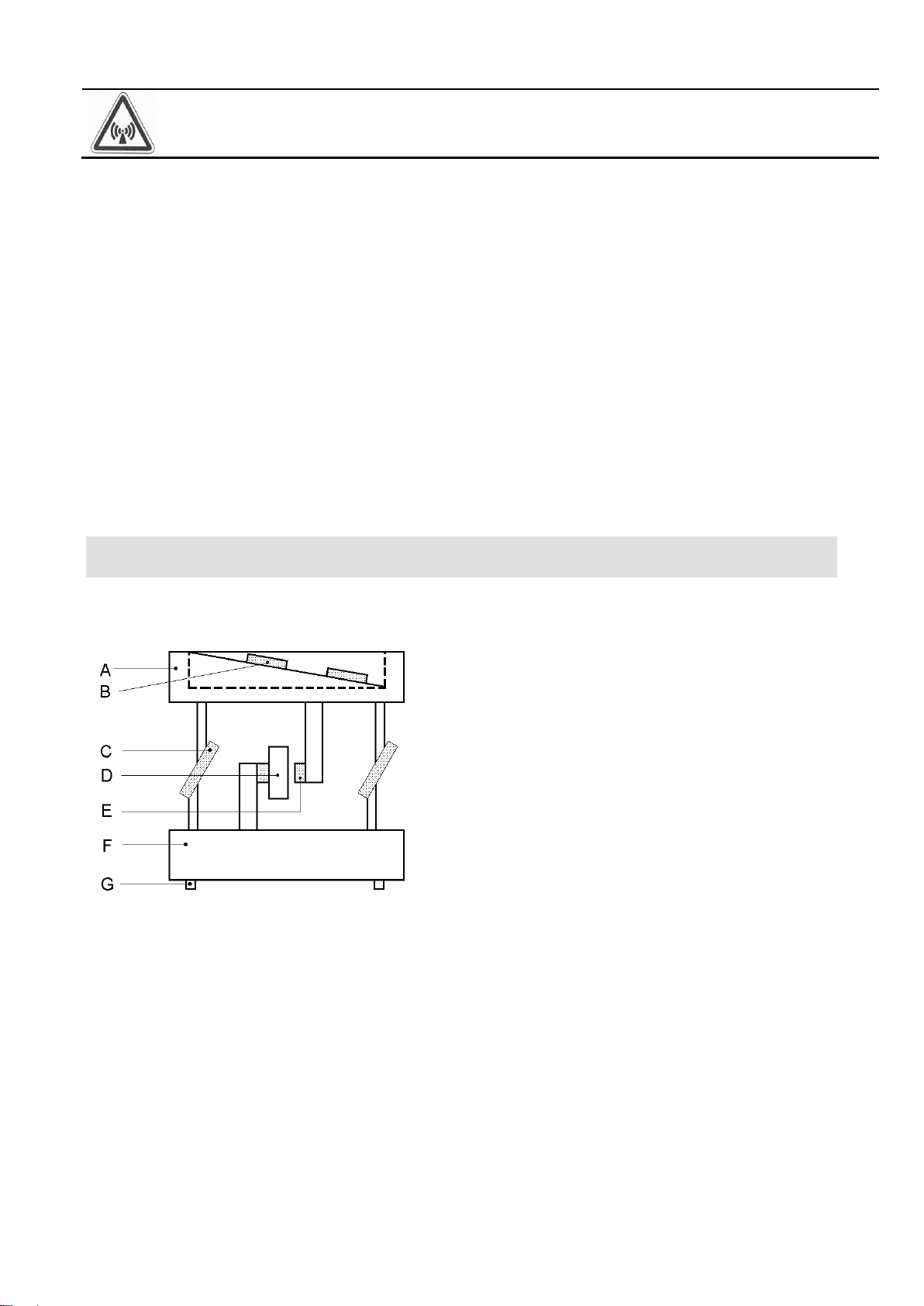
The vibratory bowl feeder may only be operated in the configuration drive unit, control unit and bowl, as speci-
fied by the manufacturer.
The vibtratory bowl feeder may not be operated in the explosive or wet area.
No additional loads may act upon the vibratory bowl feeder, apart from the bulk material, for which the special
type is designed.
Attention
It is strictly prohibited to put any safety devices out of operation!
Demands on the user
For all activities (operation, maintenance, repair, etc.) the details of the operating instructions must be
observed.
The operator has to refrain from any working method which would impair the safety of the vibratory bowl
feeder.
The operator has to take care that only authorized personnel works at the vibratory bowl feeder.
The operator is obliged to inform the operator immediately about any changed conditions at the vibratory
bowl feeder, which could endanger safety.
Attention
The vibratory bowl feeder may only be installed, put into operation and serviced by expert per-
sonnel. The binding regulation for the qualification of electricians and personnel instructed in electrical
engineering is valid, as defined in IEC 364 and DIN VDE 0105 part 1.

Rhein - Nadel Automation GmbH 5 14.04.2014
Bowl feeder VT-BA-SRC63-100-GB
Attention:
Since the electromaget-field may have an impact on persons arrying pacemakers it is recommended to
keep a minimum distance of 25 cm.
Noise emission
The noise level at the place of operation depends on the total equipment and the material to be sorted. The
determination of the noise level according to the EC-Regulations "Machinery" can therefore only be carried
out at the place of operation.
If the noise level at the place of operation exceeds the limit permitted, noise protection hoods may be used,
which we offer as accessory parts (see catalogue).
Standards and regulations
The device was built according to the following standards and regulations:
Low voltage directive 2014/35/EU
EMC directive 2014/30/EU
We assume that our product is to be
integrated in a fixed machine. The provisions of the EMC directive 2014/30/EU has to be considered by the
user.
Applied harmonized Standards
EN 60204, T.1
3 Construction and function of the
vibratory bowl feeder
Vibratory bowl feeders are used for the actuation of sorting machines. The actuation takes place by electro-
magnets. The following schematic diagram shows the function of a vibratory bowl feeder:
The drive magnet D is firmly connected with the counter-mass F. When current passes the drive magnet, it
exerts power on armature E. The power is transmitted to bowl A, which is supported by the spring assembly
C. The moving direction of the bowl is determined by the angle of the spring assemblies.
Owing to the vibrations the material to be conveyed is shortly lifted off the conveyor belt (helix of the bowl)
and it carries out little jumps (microjumps). The jump direction is in a right angle to the level of the spring
assemblies.
The drive magnet achieves its maximum magnetic force twice during a period of the alternating current. Con-
sequently the vibration frequency corresponds to the double mains frequency.
For heavy sorting installations a lower frequency of 50 Hz can be more advantageous.
The vibration frequency of your vibratory bowl feeder results from the last figure of the type designation:
-2: 100 Hz - 6000 vibrations/min.
A = Bowl
B = Material to be conveyed
C = Spring assembly
D = Drive magnet
E = Armature
F = Counter-mass
G = Vibration buffers

Rhein - Nadel Automation GmbH 6 14.04.2014
Bowl feeder VT-BA-SRC63-100-GB
A vibratory bowl feeder is a resonant system (spring-mass-system). The result is that the adjustment made at
the plant will rarely meet your requirements. Chapter 5 shows how your vibratory bowl feeder is adapted to
your requirements.
As accessory parts we are offering a spectrum of sorting bowls, which cover a wide range of application. For
special applications individual problem solutions can be manufactured.
Controlling of the vibratory bowl feeder takes place by a low loss electronic control unit. The selection of the
control unit depends on the power consumption of the vibratory bowl feeder. The following table shows the
kind of control units that can be used at the individual vibratory bowl feeders:
ESG 2000
ESK 2000
ESG 1000
SRC-N 63
SRC-N 100
The pin assignment of the bowl is shown in the table “Technical Data” (chap. 1).
Notice
Detailed information on the complete range of control units may please be taken from the operating in-
structions for control units.
All control units have got two main operating elements:
By the mains switch the vibratory bowl feeder is switched on or off.
By the turning knob the conveying capacity of the sorting unit is set.
4 Mounting
The device is completely mounted.
The vibrator has to be screwed on a strong subassembly in a dry room.
Ambient temperature –10° to + 50°C
Ensure that no contact exists between the bowl feeder in operation and other equipments. The bowl feeder is
to be firmly mounted from beneath the fastening threads on a mass of at least
15 –20 Kp.
Vibratory bowl feeder type
Hole circle
[mm]
Hole circle angle
[°]
Vibration buffer thread
SRC-N 63
40
2 x 180 °
M4
SRC-N100
70
3 x 120 °
M4
Further details on the control unit (bore plan, etc.) are please taken from the operating instructions of the
control unit separately delivered.
5 Starting
Preparations
Notice
Ensure that the machine frame (stand, under frame, etc) is connected with the protective conductor
(PE). If necessary, protection earthin must be praided on spot.
Check, whether
the vibratory bowl feeder stands in an isolated position and does not come in contact with a solid body
the sorting bowl is tightly screwed down
the connecting cable of the vibratory bowl feeder is plugged in at the control unit.
Attention
The electric connection of the vibratory bowl feeder may only be made by trained personnel (electri-
cians)! In case modifications are made at the electric connection, it is absolutely necessary to observe
the operating instructions "control units".

Rhein - Nadel Automation GmbH 7 14.04.2014
Bowl feeder VT-BA-SRC63-100-GB
the available supply voltage (frequency, voltage, power delivery) corresponds to the connecting data of
the control unit (see type plate at the control unit).
Plug in the mains cable of the control unit.
Switch on the control unit with the mains switch.
Notice
At vibratory bowl feeders which are delivered as a completely adjusted system, the optimal conveying
capacity is already set in the factory. It is marked on the scale of the turning knob with a red arrow. In this
case set the turning knob to the marking.
The optimal operative range of the vibratory bowl feeder is at a controller position of 80% at the control unit.
In case of higher deviations
(
15%) a new adjustment must be made. This adjustment is described on the following page.
In the factory the vibratory bowl feeders are approximately adjusted to standard sorting bowls (without sorting
element).
Adjustment
To set the air-gap, lift and lower the magnet coil, which is fastened with a threated pin.
Adjusting the magnet coil:
1. Fit the unit on a solid subsurface
2. Loosen the fixing screw of the magnet coil (Screw is fitted laterally at the counter mass
across the cable outlet)
3. Adjust the air-gap with the height adjusting screw of the magnet coil. This new is found lat-
erally at the counter mass between the cable outlet and fixing new of the coil magnet
4. Tighten the fixing screw
In order to guarantee an optimal sorting behaviour, the vibratory bowl feeder must be adjusted to the con-
crete operating conditions.
The adjustment is made by adding or removing leaf springs and washers.
While the spring fastening screw is loosened, you can see a change in the conveying speed.
The following graphic chart shows the resonance curve of a vibratory bowl feeder:
Notice
The resonant frequency of the vibratory bowl feeder may not correspond to the mains frequency.
Notice
The adjustment is, however, more easy with an electronic frequency converter, which you can buy from
our range of accessory parts.
The vibratory bowl feeder should be adjusted that the required conveying capacity is achieved at a controller
position of approx. 80% at the control unit.
A = Conveying speed
B = Natural frequency of the system
C = Resonance curve (not true to scale)
D = Spring power (number of springs)

Rhein - Nadel Automation GmbH 8 14.04.2014
Bowl feeder VT-BA-SRC63-100-GB
6 Maintenance
The vibratory bowl feeders are generally maintenance-free. They should only be thoroughly cleaned when
they are considerably dirty or after fluids have been spilled over them.
7 Stockkeeping of spare parts and after-sales service
The range of the spare parts available may be taken from the separate spare parts list.
In order to guarantee a quick and faultless handling of the order, please state the following data at each indi-
vidual order:
Type of equipment (see type plate)
Number of pieces needed
Spare part name
Spare part number
You will find a list of our service addresses on the back page of the cover
8 What happens, if...
Instructions for trouble-shooting
Attention
The control unit or the connecting terminal box may only be opened by an electrician. Before opening the
a.m. devices, the mains plug must be unplugged!
.Trouble
Possible cause
Remedy
Vibratory bowl
feeder does not
start at being
switched on
Mains plug of the control
Connecting cable between vibratory bowl feeder
and control unit not plugged in
Only in connection with control unit ESK 2000
Sensor gives the faulty message of pile-up, owing
to defect or maladjustment (green LED at the vibra-
tory bowl feeder STOP
Fuse in the control unit defect
Mains switch off
Magnet coil defect
Plug in the mains plug unit is not plugged
in
Plug in the 5-pole plug at the control unit
Replace the sensor or readjust it
Check whether the sensor is plugged in
Replace the fuse
Switch on the mains switch
Have the coil checked by trained per-
sonnel and , if necessary, have it ex-
changed.
The vibratory
bowl feeder
vibrates only
slightly
The control unit is set to 0%
Set the controller to 80 %

Rhein - Nadel Automation GmbH 9 Stand: 16.03.2010
Bowl feeder VT-BA-SRC63-100-GB
Rhein-Nadel Automation GmbH
Reichsweg 19/23 D - 52068 Aachen
Tel (+49) 0241/5109-159 Fax +(49) 0241/5109-219
Rhein-Nadel Automation GmbH
Zweigbetrieb Lüdenscheid
Nottebohmstraße 57 D - 58511 Lüdenscheid
Tel (+49) 02351/41744 Fax (+49) 02351/45582
Rhein-Nadel Automation GmbH
Zweigbetrieb Ergolding
Ahornstraße 122 D - 84030 Ergolding
Tel (+49) 0871/72812 Fax (+49) 0871/77131
Email [email protected]
PSA Zuführtechnik GmbH
Dr. Jakob-Berlinger-Weg 1 D –74523 Schwäbisch Hall
Tel +49 (0)791/9460098-0 Fax +49 (0)791/9460098-29
Email info@psa-zt.de
HSH Handling Systems AG
Wangenstr. 96 CH - 3360 Herzogenbuchsee
Tel +(41) 062/95610-00 Fax (+41) 062/95610-10
Internet www.rna.de Email info@handling-systems.ch
RNA AUTOMATION LTD
Hayward Industrial Park
Tameside Drive, Castle Bromwich
GB - Birmingham, B 35 7 AG
Tel (+44) 0121/749-2566 Fax (+44) 0121/749-6217
Internet www.rna-uk.com Email rna@rna-uk.com
Vibrant S.A.
Pol. Ind. Famades C/Energia Parc 27
E - 08940 Cornella Llobregat (Barcelona)
Tel (+34) 093/377-7300 Fax (+34) 093/377-6752
®
Unit C Castle Bromwich Business Park, Tameside Drive
Birmingham B35 7AG , United Kingdom
Tel +44 (0)121 749 2566 Fax +44 (0)121 749 6217
Web: www.rnaautomation.com
This manual suits for next models
1
Table of contents
Other RNA Industrial Equipment manuals
Popular Industrial Equipment manuals by other brands

Burkert
Burkert PTB 14 ATEX 2023 X operating instructions

Hugh Crane
Hugh Crane COMMANDO DUSTGUARD operating & maintenance manual

schmersal
schmersal AZM190 RK Series operating instructions

ABB
ABB HT574957 original operation manual

Bramley
Bramley 26E Service manual

Wittenstein
Wittenstein alpha Advanced SP+ ATEX MF Series operating manual