Robe ColorMix Wash I50 User manual


2
Table of contents
1. Safety instructions......................................................................................................... 3
2.Operating determinations .............................................................................................. 4
3.Description of the device ............................................................................................... 5
4.Installation....................................................................................................................... 6
4.1Fitting/Exchanging the lamp....................................................................................... 6
4.2Lamp alignment.......................................................................................................... 6
4.3 Changing the beam angle......................................................................................... 7
4.4 Rigging...................................................................................................................... 8
4.5 Connection to the mains.......................................................................................... 10
4.6 DMX- 512 connection, master/slave connection ..................................................... 11
5.DMX Protocol 8-bit ....................................................................................................... 12
6.Controller mode............................................................................................................ 13
6.1 DMX addressing ..................................................................................................... 13
6.2 Remotely controllable functions .............................................................................. 13
7. Stand - alone mode...................................................................................................... 14
8. Functions of the control panel.................................................................................... 15
8.1 Addressing .............................................................................................................. 15
8.2 Slave control ........................................................................................................... 16
8.3 Fixture informations................................................................................................. 16
8.4 Personality options.................................................................................................. 18
8.5Test sequences........................................................................................................ 19
8.6 Stand-alone setting ................................................................................................. 20
8.7 Reset function ......................................................................................................... 21
8.8 Special functions..................................................................................................... 21
9. Error and information messages................................................................................ 23
10.Technical specifications ............................................................................................ 23
11. Maintenance and cleaning ........................................................................................ 25
12. Appendix 1 - Menu map............................................................................................. 27
13. Appendix 2 - Changing the power supply settings................................................. 28
COLORMIX 150 ATWASH

3
CAUTION!
Keep this device away from rain and moisture!
Unplug mains lead before opening the housing!
FOR YOUR OWN SAFETY, PLEASE READ THIS USER MANUAL CAREFULLY
BEFOREYOU INITIAL START - UP!
1. Safety instructions
Caution ! Be careful with your operations.With a dangerous voltage you can suffer
a dangerous electric shock when touching the wires
Thisdevice hasleftour premisesin absolutelyperfectcondition. Inorderto maintainthis conditionand toensure
asafe operation,itis absolutelynecessary fortheuser tofollowthe safetyinstructions andwarning noteswritten
in this manual.
Important:
Damages caused by the disregard of this user manual are not subject to warranty.The dealer will not accept
liability for any resulting defects or problems.
If the device has been exposed to drastic temperature fluctuation (e.g.after transportation), do not switch it on
immediately.Thearisingcondensation watermightdamage yourdevice.Leavethedeviceswitchedoffuntilit has
reachedroomtemperature.
This device falls under protection-class I.The power plug must only be plugged into a protection class I outlet.
Neverlet thepower-cord comeintocontact withothercables! Handlethe power-cordandall connectionswiththe
mains with particular caution!
Make sure that the available voltage is not higher than stated on the rear panel.
Make sure that the power-cord is never crimped or damaged by sharp edges. Check the device and the power-
cord from time to time.
Alwaysdisconnect fromthe mains,whenthedevice isnotin useor beforecleaningit.Only handlethepower-cord
by the plug. Never pull out the plug by tugging the power-cord.
During the initial start-up some smoke or smell may arise.This is a normal process and does not necessarily
mean that the device is defective.
Caution: Duringthe operation,thehousing becomesvery hot.
Do not switch the device on and off in short intervals as this would reduce the lamp’s life.
HEALTH HAZARD!
Never look directly into the light source,as sensitive persons may suffer
an epileptic shock
( especially meant for epileptics) !
Please consider that damages caused by manual modifications to the device are not subject to warranty.
Keepawaychildren andamateurs !

4
2.Operating determinations
This device is a projector for creating decorative effects and was designed for indoor use only.
This device is designed for professional use, e.g. on stages, in discotheques, theatres etc.
Lightingeffects arenot designedfor permanentoperation.Consistent operation breakswillensure thatthe device
will serve you for a long time without defects.
Never run the device without lamp!
Do not shake the device.Avoid brute force when installing or operating the device.
Whenchoosing theinstallation-spot, pleasemakesure thatthe deviceis not exposedto extremeheat, moisture
or dust.There should not be any cables lying around.You endanger your own and the safety of others!
The minimum distance between light-output and the illuminated surface must be more than 0,8 meter.
Make sure that the area below the installation place is blocked when rigging, derigging or servicing the fixture.
Always fix the fixture with an appropriate safety-rope.
Onlyoperate thefixtureafter havingchecked thatthehousing isfirmlyclosed andall screwsare tightlyfastened.
Thelamp mustneverbe ignitedif thefresnel-lensor anyhousing-coveris open,asdischarge lampsmay explose
.
Themaximum ambienttemperature tamustnever beexceeded.
CAUTION!
The lens has to be replaced when it is obviously damaged,
so that its function is impaired, e. g. due to cracks or deep scratches!
Operate the device only after having familiarized with its functions. Do not permit operation by persons not
qualifiedfor operatingthe device.Mostdamages arethe resultofunprofessional operation!
CAUTION!
The lamp has to be replaced when it is damaged
or deformed due to the heat!
Please use the original packaging if the device is to be transported.
Please consider that unauthorized modifications on the device are forbidden due to safety reasons!
Never remove the serial barcode from the device as this would make the guarantee void.
If this device will be operated in any way different to the one described in this manual, the product may suffer
damages and the guarantee becomes void. Furthermore, any other operation may lead to dangers like short-
circuit, burns, electric shock, lamp explosion, crash etc.

5
3.Description of the device
Rear view of the fixture
Control panel
1- Mounting bracket 4- Bottom cover
2 -Top cover 5- Adjusting screw
3 - PC lens
6-Control board
7 -Powercord
8-Fuse holder
9- Power switch
10 - Lamp cover
11 -DMXoutput
12 -DMX input
13 - Display
14-Mode-button
15 -Enter-button
16-Up-button
17-Down-button

6
4.Installation
4.1Fitting/Exchanging the lamp
DANGER !
Install the lamp with the device switched off only.
Unplug from mains before !
To insert thelamp (CDM-SA/T150W/942):
1.Disconnect the fixture from power and allow it to cool.
2.Loosen the 2 screws „X,Y” on the lamp socket assembly at the back of the fixture.
3.Gently pull the lamp socket assembly out of the fixture.Hold this assembly while replacing the lamp.
4.Holding the lamp by its ceramic base,carefully pull the lamp straight out of the lamp socket.
5.Holding the new lamp by its ceramics base,gently insert the lamp to the lamp socket.Make sure that the lamp
is installed tightly into the lamp socket.
Do not install a lamp with a higher wattage! A lamp like this generates temperatures the device is not designed
for.Damages caused by non-observance are not subject to warranty. Please follow the lamp manufacturer‘s
notes!Do not touch the glass bulb bare hand during the installation!
6.Reinsert the lamp socket assembly and tighten the 2 screws again.
7.Align the new lamp (see instructions below)
8.Reset the "LAti/rSEt" and "LASt/rSEt"counters in the "InFO" menu on the control panel, by pressing the [
]and [ ] buttons in one time and then confirming with the [ ] button.
Do not operate this fixture with opened housing-covers!
4.2Lamp alignment
The lamp holder is aligned at the factory. Due to differences
betweenlamps,fineadjustment may improvelightperformance.
1.Switch on the fixture and after reset turn on the lamp
2.Cancel all effects, open the shutter and set the dimmer
intensity to maximum and focus the light on a flat surface
(wall)using eitherDMXcontroller or function"LAAd" inthe
"Special functions" of the control board .
3.Centerthe hot-spot (thebrightest partof thebeam)using the
3adjustment screws„A,B,C”.Turnone screwata timetodrag
thehot-spot,diagonallyacrosstheprojectedimage.Ifyoucannot
detect a hot -spot, adjust the lamp until the light is even.
To reduceahot-spot, pullthelampin byturningall threescrews
„A, B, C”
Lamp socket assembly
2fastening screws
screws „A, B, C”

7
clockwise 1/4-turn at a time until the light is evenly distributed.
If the light is brighter around the edge than it is in the center, or if light output is low, the lamp is too far back in the
reflector.„Push”thelamp outbyturningthe screws„A,B,C”counterclockwise1/4-turn atatime thelightis bright
andevenly distributed.
4.3 Changing the beam angle
If you want to change the beam angle (21°or 26°),follow the instructions:
1.Disconnect the fixture from AC power.
2.Remove the top cover (cover with display)by loosening 3 screws.
3.Loosen the screw (1) and move the lens holder (2) to the required position.
4.Tighten the screw (1) and put back the top cover.

8
4.4 Rigging
DANGERTO LIFE!
Please consider the respective national norms during the installation!
The installation must only be carried out by an authorized dealer!
Theinstallation ofthe fixturehasto bebuiltand constructedina waythat itcanhold 10timesthe weightfor 1hour
withoutany harmingdeformation.
The installation must always be secured with a secondary safety attachment, e.g.an appropriate catch net.This
secondary safety attachment must be constructed in a way that no part of the installation can fall down if the
main attachment fails.
Whenrigging, deriggingor servicing thefixture stayinginthe areabelow the installationplace, onbridges,under
highworking placesandother endangeredareasis forbidden.
Theoperatorhas tomakesurethat safety-relatingandmachine-technical installationsareapprovedbyan expert
before taking into operation for the first time and after changes before taking into operation another time.
Theoperatorhas tomakesurethat safety-relatingandmachine-technical installationsareapprovedbyan expert
after every four year in the course of an acceptance test.
Theoperator hasto makesurethat safety-relatingand machine-technicalinstallationsare approvedby askilled
persononce ayear.
The fixture should be installed outside areas where persons may walk by or be seated.
IMPORTANT! OVERHEAD RIGGING REQUIRES EXTENSIVE EXPERIENCE, including (but not limited to)
calculating working load limits, installation material being used, and periodic safety inspection of all installation
material and the fixture. If you lack these qualifications, do not attempt the installation yourself, but instead use
aprofessionalstructural rigger.Improper installationcanresult inbodily injury and.ordamage toproperty.
The fixture has to be installed out of the reach of people.
If the fixture shall be lowered from the ceiling or high joists, professional trussing systems have to be used.The
fixture must never be fixed swinging freely in the room.
Caution: Projectorsmay causesevereinjuries whencrashingdown! Ifyou havedoubts concerningthe safety of
a possible installation, do NOT install the projector!
Beforeriggingmakesure thattheinstallation areacanhold aminimumpoint loadof10 timesthefixture’sweight.
Danger of fire !
When installing the device, make sure there is no highly inflammable
material (decoration articles, etc.) in between a distance of min. 0,5 m.
CAUTION!
Make sure that the device is fixed properly! Ensure that
the structure (truss) to which you are attaching the fixtures is secure.
The projector can be placed directly on the stage floor or rigged in any orientation on a truss without altering its
operationcharacteristics .
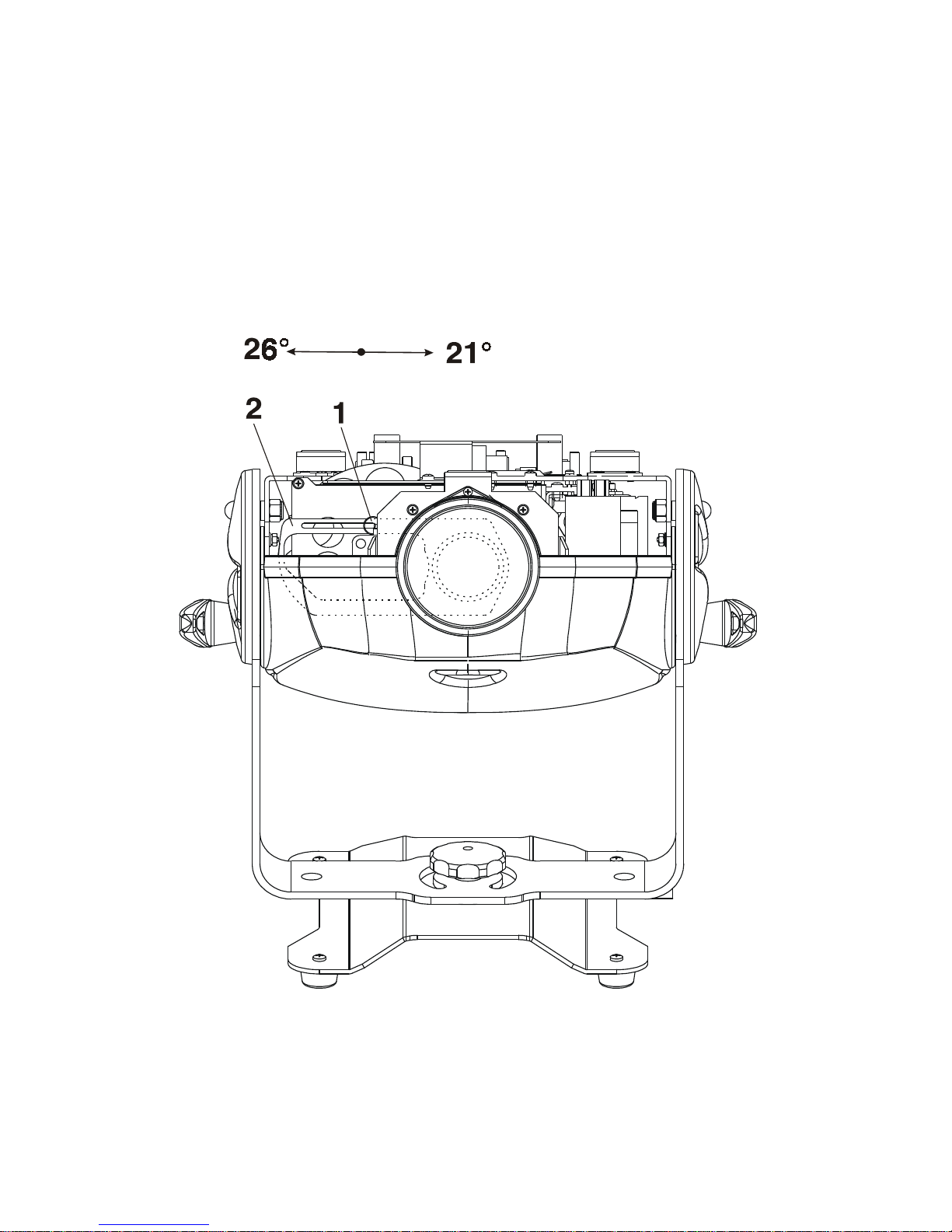
Overhead installation.
The mounting bracket provides 3 holes (a diameter of13mm) and 2 quarter-circle slots.
To adjusttheinclination-angle,loosenthe2 adjustingscrews.Turn theprojectorto thedesiredangle andretighten
the adjusting screws.

9
For overhead use, always install a safety rope that can hold at least 10 times the weight of the fixture. Pull the
safety rope through the mounting bracket and over the trussing system etc.
Floor installation.
The projector can stand directly on the floor by standing on the removable stand which is mounted with the nut
M8 to the projector's mounting bracket.
Mountingbracket
Adjustingscrew
Mountingbracket(groundplan):
Measurementsare
in milimetres
Nut
Removablestand

10
DANGERTO LIFE!
Before taking into operation for the first time,the installation has to be
approved by an expert!
When installing fixtures side-by-side,
avoid illuminating one fixture with another!
Removablestand:
Measurementsare
in milimetres
4.5 Connection to the mains
Verify the power supply settings before applying power!
If you wish to change the power supply settings,see the chapter Appendix.
Connectthe fixturetothe mainswith theenclosedpower plug.Ifyouneed toinstall otherpowerplug onthepower
caple,follow the identification table below.
The earth has to be connected!
The occupation of the connection-cables is as follows:
Cable (EU) Cable (US) Pin International
Brown Black Live L
Lightblue White Neutral N
Yellow/Green Green Earth
Do not connect the projector to a dimmer system!

11
4.6 DMX- 512 connection, master/slave connection
Only use a shielded twisted-pair cable designed for RS-485 and 3-pin XLR-plugs and connectors in order to
connect the controller with the fixture or one fixture with another.
Occupation of the XLR-connection:
DMX - output DMX-input
XLR mounting-socket: XLR mounting-plug:
Building a serial DMX-chain:
Ifyou areusingthe standardcontrollers,you canconnectthe DMX-outputof thecontroller directlywith theDMX-
input of the first fixture in the DMX-chain. If you wish to connect DMX-controllers with other XLR-outputs, you
needto useadapter-cables.
Connect the DMX-output of the first fixture in the DMX-chain with the DMX-input of the next fixture. Always
connect output with the input of the next fixture until all fixtures are connected.
Caution: At the last fixture, the DMX-cable has to be terminated with a terminator.Solder a 120 Ohm resistor
between Signal (–) and Signal (+) into a 3-pin XLR-plug and plug it in the DMX-output of the last fixture.
Building a master/slave-chain:
Connect the DMX-output of the master fixture in the data-chain with the DMX-input of the first slave. Always
connect output with the input of the next slave until all slaves are connected (up to 9 fixtures).
Caution:It’snecessaryto insertthe XLRtermination plug(with 120Ohm)into theinput ofthemaster fixtureand
into the output of the last slave fixture in the link in order to ensure proper transmission on the data link.
1-Ground
2 - Signal (-)
3 - Signal (+)
1-Ground
2 - Signal (-)
3 - Signal (+)

12
5.DMX Protocol 8-bit
Channel Value Function Type of control
1 Colours
0 Open/white proportional
10 Turquoise proportional
21 Red proportional
32 Cyan proportional
42 Lightgreen proportional
53 Magenta proportional
64 LightBlue proportional
74 Yellow proportional
85 Green proportional
96 Pink proportional
106 Blue proportional
117 Orange proportional
128-189 Forwards rainbow effect from fast to slow proportional
190-193 No rotation proportional
194-255 Backwards rainbow effect from slow to fast proportional
2 Dimmer intensity
0-255 Intensity from 0 to 100% proportional
3 Shutter,Strobe,Reset
0 Shutterclosed step
1-63 Light intensity from 0 to 100% proportional
64-95 Shutter open step
96-127 Strobe-effect from slow to fast (max 8 flashes/s) proportional
128-139 Reset step
140-159 Shutter closed step
160-175 Pulse-effect in sequences with increasing speed proportional
176-191 Pulse-effect insequenceswith decreasingspeed proportional
192-223 Random strobeeffect withincreasing speed proportional
224-255 Shutteropen step

The COLORMIX 150 AT WASH WASH can be operated with a controller in controller mode or without the
controllerin stand-alone mode.
Both modes are described in the texts below.
6.Controller mode
The fixtures are individually addressed (001-510) on a data link and connected to the controller.The fixtures
respond to the DMX signal from the controller.
6.1 DMX addressing
Thecontrol panelon thefront sideof thebaseallows youto assignthe DMXfixtureaddress, whichis definedas
the first channel from which the COLORMIX 150 ATWASHWASH will respond to the controller.
If you set, for example, the address to channel 5, the COLORMIX 150 ATWASHWASH will use the channel 5 to
7 for control.
Please,besure thatyoudon’t haveanyoverlappingchannels inorderto controleachCOLORMIX 150ATWASH
correctly and independently from any other fixture on the DMX data link.
If two, three or more COLORMIX 150 ATWASH are addressed similarly, they will work similarly.
Foraddress setting,please refertothe instructionsunder "Addressing"(menu"A001").
Controlling:
After having addressed all COLORMIX 150 AT WASH , you may now start operating these via your lighting
controller.
Note:After switching on, the COLORMIX 150 AT WASH will automatically detect whether DMX 512 data is
received or not.If there is no data received at the DMX-input, the display will start to flash "A001" with actually
set address.
This situation can occur if:
- the 3 PIN XLR plug (cable with DMX signal from controller) is not connected with the input of the COLORMIX
150ATWASH
- the controller is switched off or defective, the cable or connector is defective or the signal wires are swap in the
inputconnector.
Note:It’s necessary to insert the XLR termination plug (with 120 Ohm) to the last fixture in the link in order to
ensure proper transmission on the DMX data link.
6.2 Remotely controllable functions
Colour - wheel
The COLORMIX 150 AT WASH contains a colour wheel with 12 colour positions - 11 of these with dichroic
coloursand thelast onewhite.Thecolour-wheel can bepositioned betweentwoadjacentcolours inanyposition.
Itis alsopossible torotatethe colour-wheel continuouslyat differentspeeds("Rainbow effect“inboth directions).
Dimmer
The dimming (0-100%) is provided by the mechanical dimmer unit.
Shutter/Strobe
Theshutter is executedbythe mechanicalshutter unit.This unitmayalso beused forstrobe effect(1 -8 flashes
persecond).

14
7. Stand - alone mode
The fixtures on a data link are not connected to the controller but can execute pre-set programs which can be
different for every fixture.To set the program to be played,see the "Stand-alone setting" ( menu "St.AL.").
"Stand-alone operation" can be applied to the single fixture (the fixture may be set to the master /slave mode or
controller mode ) or to multiple fixtures operating synchronously.
Synchronous operation of multiple fixtures requires that they must be connected on a data link and one of them
is set as a master (master mode) and the rest as the slaves (slave mode).The slaves are assigned to SLA1-
SLA9 and on the certain slave address can be connected only one fixture.To set the fixture as the master or
slave , see the "Addressing" (menu "A001").
If the master fixture runs a reset or plays test(program) ,all slaves will execute these acts too.
You can't play or edit any programs on the slaves by their control panels if the master is switched on and
connected to the master/slave chain.
The master fixture starts simultaneous program start in the other slave fixtures.All fixtures have a definite,
synchronizedstartingpoint whenplayingbacktheirprograms.Thenumberof runningprogram isthe samein all
slaves and depends on the master's choice (menu "St.AL." ).Every fixture runs its program repeatedly ,starting
the program step No.1 when requested by the master .
Forexample:
If the slave fixture has a shorter program length, it will continously repeat its program until the master fixture
finishes its own program and restarts its program running (slave 1- prog.step 3 will not be finished).
If the slave fixture has a longer program length, it will restart at prog.step 1 before it completes all itsprog.steps
(slave 2 - prog.step 5 will not be played)- see the picture bellow.
Note:Disconectthe fixturesfromthe DMXcontrollerbefore master/slaveoperating ,otherwisedatacollisions can
occur and the fixtures will not work properly!
It’s necessary to insert the XLR termination plug (with 120 Ohm) into the input of the master fixture and into the
output of the last slave fixture in the data link in order to ensure proper transmission on the data link.
From the master's control panel is possible to control any slave in a master/slave chain.
Starting point
Restart

15
8. Functions of the control panel
The control panel situated on the front side of the base offers several features.You can simply set the DMX
address,master/slave mode, read the number of lamp or unit hours, run test, make a reset and also use many
functions for setting and service purposes.
Themain menuof thecontrol panelis accessedby pressingthe[ ] button -press thisone somany timesuntil
thedisplay showsmessage"A001" (with actuallystoredaddress). Browsethrough the menuby thepressing [
]or [ ] buttons - the display shows step by step these messages: A001,SLCt, InFO,PErS,tESt, StAL,rESE,
SPEC.Press [ ]if youwishto selectone ofthem.The functionsare describedin thefollowingsectionsand the
function hierarchy is shown below.
8.1 Addressing
By this menu you can set the DMX address or address the fixture as a master/slave.
- DMX addressing
1. Press the []- button so many times until the display shows message "A001" (with actually stored address).
2. Press [ ]-button and use the [ ] and [] buttons to select"dM.Ad."-menu.
3. Press[ ]-button(the letter "A" flashes) and by [ ] and [ ] buttons select required address (001 -
510), press [ ]-button to confirm.
4. Select "M.ASL."-menu,press[Enter]-buttonand use[ ] and [ ] buttonsto select"d.AbL."(no masteror
slave),press [ ]-button to confirm.
5.Press the []- button.Choosen address is shown on the display.
If message "A001" (with actually stored address) flashes-no DMX data received at the DMX-input.
- Master/slave adressing
1. Press the []- button so many times until the display shows message "A001" (with actually stored
address).
2. Press [ ]-button and use the [ ]and [ ] buttons to select "MA.SL."-menu.
3. Press [ ]-button(display flashes) and select"MASt"(to set the fixture as the master in a chain of multiple
fixtures) or "SLA.1"-"SLA.9" (to set the fixture to be the slave in a chain of multiple fixtures) and press [ ]
to confirm. If you want address no master or slave, select "d.AbL.".
4.Press the []- button.Choosen address is shown on the display.
If message "MASt." fast flashes-DMX signal is received at the DMX-input- disconnect DMX controller!
Only one fixture may be the master.Up to the 9 slaves may be connected to the master and on the certain
address can be connected only one slave fixture (SLA1-SLA9).
Note:Disconectthe fixturesfromthe DMXcontrollerbefore master/slaveoperating ,otherwisedatacollisions can

16
occur and the fixtures will not work properly!
If the fixture is set as the master and DMX signal is connected to its input,the error massage "MAEr" will appear
onits displayand thefixture's addresswill beset toits DMX addressin orderto respondto DMXsignal fromthe
controller.
Forexample:
The master fixture has this address setting:"dM.Ad."-menu.........A004
"MA.SL."-menu........MASt (is displayed)
The DMX signal is connected to the master fixture.The message "MAst" starts fast flashing and after 20s error
massage "MA.Er" appears on its display and the fixture automatically will be switched to its DMX address
(masteraddress isdisabled).
Now the fixture has the address setting: "dM.Ad."-menu.........A004 ("A004"/" MA.Er"blinks )
"MA.SL."-menu.........d.AbL.
If the fixture is set as the slave and DMX signal is connected to its input,the fixture will respond to DMX signal
fromthe controller(in dependenceonthe fixture'sDMX address).
8.2 Slave control
This function allows you to control the slaves from the master's control panel in a master/slave operation.
Select this function from the main menu and press [ ]-button.Browse the list of all connected slaves ("SL.C.1"
- "SL.C.9") by pressing [ ] and [ ] bottons.Select the desired slave and press []]-button.The slave's control
panel is available from the master's control panel.
If no slave is connected to the master,massages "SL.C.1","SL.C.2","SL.C3"..."SL.C.9" still round repeat.
Note:This function is available from the master fixture only.
8.3 Fixture informations
The menu allows you to read an useful information about the fixture as the lamp life,lamp strikes,software
version, etc.
Press [ ]or [] buttons to select the desired option and press [ ] to see the value or next submenu.
Power On time
-By this option you can read the total number of the operation hours since the
COLORMIX 150 AT WASH has been fabricated.Press [ ] or [ ] to return to
themenu.

17
-Thenumber ofthehours thatthe COLORMIX150 ATWASH hasbeenpoweredOn
since the counter was last reset.Press [] or [ ] to return to the menu.In
order to reset this counter to 0, you have to hold the [] and [ ]-button and
press the [ ]-button.
Lamp On time
-This option enablesyou to read the total number of the operation hours with the lamp
on since the COLORMIX 150 ATWASH has been fabricated.Press [ ] or [ ] to
returnto themenu.
-The number of hours that the lamp has been powered On since the counter was last
reset.Press [ ]or [ ] to return to the menu. In order to reset this counter to 0,
you have to hold the [] and [ ]-button and press the [ ]-button.
Lamp strikes
- By this option you can read the total number of the lamp strikes since the
COLORMIX 150 ATWASH has been fabricated.Press [ ]or [ ] to return to
themenu.
-The number of the lamp strikes since the counter was last reset.Press [ ]
or [ ] to return to the menu. In order to reset the counter to 0, you have to hold
the [ ] and [ ]-button and press the [ ]-button.
- DMX values
Readout DMX values of each channel received by the fixture. Use the [] and [ ] buttons to select desired
channel and press [ ]to read its value coming to the fixture or [ ] to cancel and return to the menu.
- Software version
By this function you can read the software version of the display module. Press [ ] to read its value or [
]to return to the menu.

18
8.4 Personality options
Theseoptions allowyouto modifyCOLORMIX 150ATWASHoperatingbehavior.
Press[ ] and [ ]buttons to select the desired option and press [ ] to set the value or to see next submenu.
- DMX presetting
The function makes possible to select DMX- channels settings (if they exist)
Channel Mode 1 (default)
1 Colours
2 Dimmer
3 Shutter,Strobe,Reset
- Display adjusting
This function allows you to adjust the display settings:
- Display -intensity
With this function you can adjust the display intensity from 20% to 100% . Use the [ ] or [ ]
buttons to select the level of the display intensity and press [ ] to confirm or [ ] to cancel and
returnto themenu.
- Display-reverse
With this function, you can rotate the display by 180°. Use the [] or [] buttons to select "normal
display" or "display turned by 180°" and press [ ] to confirm or [ ] to cancel and return to the
menu.
- Display-On
This function allows you to keep the display on or to turn off automatically 2 minutes after last
pressing any button on the control panel. Use the [] or [ ] buttons to select "On" if you wish to
keep the display on or "Off" if you wish to turn off automatically 2 minutes after last pressing any

19
button on the control panel and press [ ] to confirm or [ ] to cancel and return to the menu.
- Microphone -sensitivity
With this function you can adjust the microphone sensitivity from 1(maximum) to 20(minimum) . Use the [ ] or
[ ] buttons to select the level of the microphone sensitivity and press [ ] to confirm the chosen level or [
]to cancel and return to the menu.
Example:
underexited right level overexited
(upper segment blinks by the bass rhythm)
- Default settings
Press [ ] to reset all fixture personalities (not the adjusting functions) to the default values. On the display will
appear "rSt" meaning that the fixture makes the reset. See the table of personality setting and their default
positions.
8.5 Test sequences
Thisfunction allowsyouto runa specialdemo-test sequenceswithout anexternalcontroller,which willshow you
some possibilities of using COLORMIX 150 AT WASH. Press []-button to run the test.If the test program is
running,messages "run/test"blinkon thedisplay.
If youwanttopause therunnnigprogramin therequiredposition, pressthe[ ]-button(messages"PAUS"/"test"
blink).Tocontinue theprogramrunning,press the[ ]-buttonagain.
Personality Display Default values
(SHADED)
Display intensity
Display-reverse
Display-On
Musictrigger
Microphone
sensitivity

20
8.6 Stand-alone setting
Thismenu offersoptions forstand-alonemode asa selectionofthe playingprogram,programmingand modifying
currentprograms.
- Music trigger
TheCOLORMIX150 ATWASHenablesthesound controlof therunning programsvia thebuilt-inmicrophone.Use
the [ ] or [] buttons to select "On" if you wish this feature or "Off" if you don’t wish this feature and press [
] to confirm or [ ] to cancel and return to the menu.
-Presetting playback
This function allows you to select the the program which will be played in the stand-alone mode after switching
the fixture On.Use the [] or[ ] buttonsto selectdesired program("tESt"-bilt-in program)or"OFF" if youdon't
want trigger anyprogram after switching the fixtureOn and press [ ]toconfirm or[ ]to cancelandreturn tothe
menu.Selected program will be played continuously in a loop as long as it appears on the display.
This option should be set "OFF" for all slaves in the master/slave chain by reason of the right program starts.
For example:You have selected program "PrG.3" in this menu and:
thisfixture isset asa singlefixture (master/slaveorcontroller operating)-thefixture will runitsprogram "PrG.3".
this fixture is set as a master in a data chain- the fixture will run its program "PrG.3".
this fixture is set as a slave in a data chain- the fixture will run its program according to the master(ifthemaster
runs its own program "PrG.1", the slave will run its own program "PrG.1"also).
Note:Ifthe fixtureoperates inthecontroller mode(DMX controlleris connected)andany programfromthis menu
isselected ,inthis case thefixture willnotrespond tothe DMX controllerafter switchingOnand willplay selected
program.
- Playing program
This function allows you to run a bilt-in program "tESt" and the 3 freely-programmable programs
"PrG.1,PrG.2,PrG.3" .Press [ ] or [ ] buttons to select the desired program and press [ ] to run the
program which will be played continuously in a loop.
If you want to pause the runnnig program in the required position, press the [ ]-button(messages"PAUS"/"
program No."blink).Tocontinuethe programrunning,press the[ ]-buttonagain.
Note:If the fixture operates in the controller mode ( DMX controller is connected) and any program from this
function is selected in this case the fixture will not respond to the DMX controller and will play selected program.
You can't play programs on the slave fixtures from their control panels if the master fixture is switched On and
connected to the slaves (playing is forced by the master).
Other manuals for ColorMix Wash I50
1
Table of contents
Other Robe Floodlight manuals

Robe
Robe DT Series User manual

Robe
Robe Digital Spot 7000 DT User manual

Robe
Robe Robin square User manual

Robe
Robe ColorWash 575 AT ZOOM User manual

Robe
Robe Robin BMFL WashBeam User manual

Robe
Robe ColorWash 1200E AT User manual

Robe
Robe Spot 575 XT User manual

Robe
Robe Color Wash 575 AT Zoom AT series User manual

Robe
Robe 1200 Color Spot User manual

Robe
Robe ArcPix-US User manual