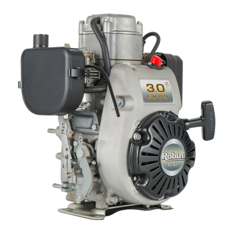
Robin EH18V OHV User manual

SERVICE
MANUAL
IVIodel
EH18V OHV
396S322

ROBIN
AMERICA, INC.
ROBIN
TO
WISCONSIN
ROBIN
ENGINE
MODEL
CROSS REFERENCE
LIST
ROBIN
EY08
EY15
EY15V
EY20
EY2OV
EY23
EY28
EY3
5
EY40
-
EY45V
EY2
1
EY44
EY18-3
EY25
EY27
EH11
EH12
EH15
EH17
EH21
EH25
EH30
EH30V
EH34
EH34V
EH43V
EC13V
DY23
DY27
DY30
DY3
5
DY41
WISCONSIN
ROBIN
SIDE
VALVE
W
1-080
W1-145
W1-145V
W1-185
W1-185V
W1-230
W 1-280
W
1-340
W 1-390
Wl-45OV
EY21W
EY44W
EY18-3W
EY25W
EY27W
OVERHEAD
VALVE
WO1-115
wo1-120
WO1-150
WO1-170
wo1-210
WOl-250
WO 1-300
WO1-300V
WO1-340
WO
1
-340V
WO 1-43OV
TWO CYCLE
WT1-125V
DIESEL
WRD
1-230
WRD
1-270
-1-300
WRD1-350
WRD1-410
0
0
0

CONTENTS
.
Section
Title
Page
1
.SpEClF[CATlONS
.........................................................................................
1
2.
PERFORMANCE............................................................................................
2
2-1 MaximumOutput
....................................................................................
2-2
Maximum Torque
...................................................................................
2
2
2-3 PerformanceCurves
...............................................................................
2
3
4.GENERAL DESCRIPTION OF ENGINE COMPONENTS .................................
3
3
.FEATURES
...................................................................................................
4-1
4-2
4-3
4-4
4-5
4-6
4-7
4-8
4-9
4-1
0
4-11
4-12
4-13
4-1
4
4-1
5
5
.DISASSEMBLY AND REASSEMBLY
............................................................
11
.
11
11
12
27
5-5
Break-inOperation
...............................................................................
40
41
6-1Flywheel Magneto
................................................................................
41
41
5-1 PreparationsandSuggestions
..................................................................
5-2 Special
Tools
.......................................................................................
5-3
DisassemblyProcedures
........................................................................
5-4 ReassemblyProcedures
.........................................................................
6
.
MAGNETO
..................................................................................................
6-2 Basic The0
ry
.......................................................................................
6-3
WiringDiagram
....................................................................................
42
7.AUTOMATlC DECOMPRESSlON SYSTEM
..................................................
43
8.CARBURETOR
...........................................................................................
44
.
8-1 Operation andConstruction
....................................................................
44
45
47
47
8-2
DisassemblyandReassembly
.................................................................
9
.
STARTING SYSTEM
...................................................................................
9-1Recoil Starter
........................................................................................

Section
Title
Page
10.
TROUBLESHOOTlNG
..............................................................................
51
10-1 StartingDifficulties
................................................................................
51
10-2 Engine Misfires
....................................................................................
52
10-3 EngineStops
.......................................................................................
52
10-4 EngineOverheats
.................................................................................
10-5 Engine Knocks
.....................................................................................
10-6
EngineBacMiresThrough Carburetor
........................................................
53
52
53
11
.
lNSTALMTlON
.......................................................................................
11-1 Installing
.............................................................................................
11-2 Ventilation
..........................................................................................
11-3 ExhaustGas Discharge
.........................................................................
54
54
54
54
12
. SERVICE DATA
......................................................................................
55
55
12-1 Clearance DataandLimits
......................................................................
12-2 Torque Specifications
............................................................................
61
12-3 Oil Grade Chart
....................................................................................
61
13.
MAINTENANCE AND
STORAGE
.............................................................
62
13-1 DailyMaintenance(Every
8
Hours)
............................................................
62
13-2 Initial
20
Hours Maintenance
...................................................................
13-3
Every
50
Hours (10 Days) Maintenance
.....................................................
62
13-4 Every 100-200 Hours (Monthly) Maintenance
.............................................
63
13-5 Every
500-600
HoursMaintenance
..........................................................
63
13-6 Every
1
000
Hours (Yearly)Maintenance
....................................................
63
13-7 Engine Storage
....................................................................................
63
62
..

1.
SPECIFICATIONS
Model
EH18V
TY
Pe Air-Cooled, 4-Cycle,Vertical Shaft, OverheadValve, GasolineEngine
Bore
X
Stroke
67
X
52
mm
(2.64
X
2.05
in.)
Piston Displacement
183
cc
(11.16
c,u.in.)
Maximum Horsepower
4.4/3600
KW/
rpm
(6/3600
HP/rpm)
1.29
/
2700
kg-m
/
rpm
(9.3/2700
ft. Ibs/rpm)
MaximumTorque
~ ~ ~~~~
Rotation
'
'
ForcedAirCooling
Cooling
Counterclockwise
As
Viewd FromPTO Shaft Side
~
Lubrication
HorizontalDraftType
Carburetor
Automobile
Oil
SAE
#20, #30or 1OW-30
Lubricant
Oil PumpType
Fuel
I
Automobile Gasoline
FuelFeed Gravity Type
~ ~~ ~ ~~
Governor System
FlywheelMagneto (Solid State)
Ignition System
Centrifugal FlyweightType
Spark Plug CHAMPION
L86C
Starting System
17
kg
(37.5
Ibs.)
DryWeight
Recoil
Starter
Dimensions Without
P.T.0
Shaft
LXWXH
409
X
372
x
31
1
mm
(16.10
X
14.65
x
12.24
in.)
Specifications and dimensions are subject to changewithout notice.
-1-

2.
PERFORMANCE
2-1
MAXIMUMOUTPUT
The maximum output
of
an engine
is
such a standard power
as
produced by the engine with
its
throttle
valvefullyopenedafteritsinitialbreak-inperiodwhenallthemovingpartsareproperlywornin.
Therefore,anewenginemaynotproducethemaximumoutputinthebeginningbecausethemoving
parts arenot in a properly worn-in condition.
2-2
MAXIMUMTORQUE
The maximum torque indicates the torque at the output shaft when the engine is producing the maximum
output.
2-3
PERFORMANCECURVES
EH18V
5.2;
(7.
0
4.41
(6.0
7.4!
(2.
0
Tn"--r
""_~_
"""
"""_
"""
2000240028003200
3600
REVOLUTlON
-
r.p.m
"i
-2-

3.
FEATURES
1.
Theoverheadvalvedesignofferscompactness,lightweightandidealcombustioncharacteristics
2.
The parts
such
as a large capacity muffler, dual element air cleaner reduce noise
to
a minimum level.
3.
The automatic decompression system offers easy and sure starting.
4.
Themufflerandcarburetorarelocated
on
oppositesides,makingthearrangements
for
coolingair
5.
The oilpumpandoilfilterprovideexcellentlubricationregardless of enginepostureduring
6.
This engine
is
offered in two stylish versions.
7.
The Pro-Poly version engine is covered with
a
stylishly designed
shroud
with the
'8.
The Classic Steel version does not have the shroud or combined fuel tank.
resulting in more power
from
less fuel and prolonged engine life.
flow
much easier in the designof power equipment.
operation.
fuel tank incoroprated intoit.
4.
GENERALDESCRIPTION
OF
ENGINECOMPONENTS
4-1
CYLINDERANDCRANKCASE
Thecylinderandcrankcaseissinglepiecealu-
minumdiecasting.Thecylinderliner,made of
specialcastiron,ismoldedintothealuminum
casting.
Thecrankcasehasamountingsurface
on
the
output shaft side, where the main bearing cover is
attached. (See Fig.
4-1.)
4-2
MAINBEARING
COVER
The main bearing cover is an aluminum
diecasting,which is mounted
on
theoutputshaft
side of thecrankcase.Removethemainbearing
cover
to
inspect inside
of
the engine.
Themainbearingcoveralsofunctionsasanoil
pan, with,atrochoid
oil
pump and
oil
filler.
(See Fig.
4-2.)
..
Fig.
4-1
Fig.
4-2
-3-

4-3
CRANKSHAFT
Thecrankshaftisaforgedcarbonsteel,andthe
crank pin
is
induction-hardened.ThePTOend
of
theshafthasacrankshaftgearwhichispressed
intoposition.(See
Fig.
4-3.)
CRANKSHAFT
GEAR
Fig.
4-3
44
CONNECTING
ROD
ANDPISTON
Theconnectingrod
is
aforgedaluminumalloy,
and its large and small ends function as bearings.
The piston
is
analuminumalloycasting,and
4-5
CAMSHAFT
Thecamshaft isa hollowshaped
and
made of
specialcast iron withthecamshaftgearcasted
together.
A
centrifugal decompression lever is assembled
on
thecamshaft.Thelubricationoil
pump
isdriven
by the groove
on
the endof the camshaft.
(See Fig.
4-5.)
Fig.
4-4
Fig.
4-5
r,
-4-

4-6
VALVEARRANGEMENT
The intake valve is located at flywheel side
of
the
Hardalloyvalveseatsaremolded in thecylinder
'
cylinderhead.
II
n
head and stellite is fused to the exhaust valve face.
The cylinder baffle leads cooling air to the exhaust
valve area for the optimum cooling.
(See
Fig.
4-6.)
EXHAUST
Vi
Fig.
4-6
4-7
CYLINDER HEAD
Thecylinderhead,isanaluminumdiecasting,.
which utilizes wedge type combustion chamber for
the highest combustion efficiency.
(See Fig.
4-7.)
Fig.
4-7
4-8
GOVERNORSYSTEM
The governor is a centrifugal flyweight type which
ensuresconstantoperationattheselectedspeed
against load variations.
Thegovernorgearwithgovernorweightsis in-
stalledonthebearingcoveranddriven
by'
the
camshaft gear. (See Fig.
4-8.)
Fig.
4-8
-5-

4-9
COOLING SYSTEM
The large fins
on
the flywheel provide sufficient cooling air capacity for the inlet and exhaust area and
cylinder.
The cylinder baffle helps the cooling air flow efficiently.
4-1
0
LUBRICATION
EH18V
has a trochoid pump outside the main bearing cover that is driven by the camshaft.
EH18V
uses
forced
splash
type lubrication.
(See
Fig.
4-9.)
/
CAMSHAFT
M6
FLANGE BOLT
...
1
pce.
OIL
SHELTER
PLATE
M,
AIN BEARING
COVER
OIL PUMP
COVER
&-
M6
FLANGE
BOLT
...
4pcs.
Fig.
4-9
-6-

4-1
1
IGNITION
SYSTEM
The
ignitionsystem
is
atransistorcontrolled
magnetoignitionsystemwhichconsists of a
fly-
wheel and an ignition coil with a built in transistor
mounted on the crankcase.
Thissystemhasanautomaticignitiontiming
advancing for easier starting. (See Fig.
4-10.)
For details, referto page
39,
section
6.
4-12
CARBURETOR
Theenginesareequippedwithahorizontaldraft
carburetor
that
hasafloatcontrolled
fuel
system
and a fixed main jet.
Thecarburetorsarecalibratedcarefullyforthe
surestarting,
good
acceleration,lowfuelcon-
sumption and sufficient output.
Forthe-datails,refer
to
page42,section
“8
CARBURETOR”.
(See
Fig.
4-11.)
4-13
AIR
CLEANER
Theair-cleaner
is
aheavy-dutytypewithadual
.
elementsystem.(See
Fig.
4-12.)
-7-
Fig.
4-1
1
WING
BOLT
I;’
<
CLEANERCOVER
PRIMARYELEMENT
GROMMET
eo
#(URETHANE FOAM)
SECONDARYELEMENT
(PAPER ELEMENT)
.
:’
.
.’
J
SECONDARYELEMENT
PAPER ELEMENT)
Fig.
4-12

4-14
DECOMPRESSION
SYSTEM
An
automaticdecompressionmechanismwhich
opensexhaustvalve
before
thepistonreaches
compressiontop is assembled
on
thecamshaftfor
easy starting. (See
Fig.
4-13)
For details, refer
to
page
41,
section
7.
[
AUTOMATICDECOMPRESSION
SYSTEM
&$
RETURNSPRING
n
-a-

4-15
SECTIONAL
VIEW
OF
ENGINE
RECOIL
STARTER
\
BLOWER
HOUSING
I
MAIN
BEARINGCOVER
CRANKSHAFT
-9-

SPARK
PLUG
MUFFLER
CONNECTING
ROD
-
10
-

5.
DISASSEMBLY
AND
REASSEMBLY
5-1
PREPARATIONSANDSUGGESTIONS
1)
When disassembling the engine, remember the locations
of
the individual parts
so
that they can be
reassembledcorrectly. If youareuncertain of identifyingsomeparts,
it
issuggestedthattags
be
attached to them.
Have boxes ready to keep disassembled parts
by
group.
To
prevent missing and misplacing, temporarily assemble each group
of
disassembled parts.
Carefully handle disassembled parts, and clean them with
oil
if
necessary.
Use the correct tools
in
the correct way.
5-2
SPECIAL
TOOLS
I
Tool No.
I
Tool
I
Use
I
I
228-
95003-07
I
Pistonring compressor
I
For placing piston ring
I
I
Market
parts
I
Flywheel puller
1
For
pulling
off
the flywheel
I
PISTON
RING
COMPRESSOR
/
/
FLYWHEELPULLER
Fig.
5-1
-
11
-

5-3
DISASSEMBLY PROCEDURES (CLASSIC STEEL)
/
(PRO POLY)
~~
Step
I
Part
toremove
I
Procedures
I
~~
Remarks
I
Tool
'I
Spark
plug
Remove spark plug cap and sparkplug.
19mm
plug wrench
II
Oil
drain,
oil
14mmboxwrench
(2)
Remove
oil
drain
plug
and
drain
oil.
filter
and
(1)
Remove
oil
gauge.
(3)
Remove oil filter.bracket
(4)
Remove
oil
filter bracket.
lOmm
box
wrench
M6X
12mm
bolt
....
2pcs.
OILGAUGE
y
T
mm
SPARKPLUG
,
'
OILGAUGE
p
T
SPARKPLUGLTER
OIL FILTER BRACKET
'
OIL DRAIN PLUG
-
M6
BOLT
'..
2pC~.
LTER
~AC
clni
r
...
gnrc
OIL FILTERBRACKET
'
OIL
DRAIN
PLUG
Fig.
5-2
-
12-

5-3
DISASSEMBLY PROCEDURES (CLASSIC STEEL) -CONTINUED
M6
FL
Part
to
remove
Recoil starter
Fuel tank
Procedures
Remove recoil starter from the engine.
M6X8mm
bolt
-0..
4pcs.
(1) Removefuel tank.
(2) Remove fuel pipe from the fueltank.
(3)
Remove side guard.
M6
X
12mm
bolt
*
-
Zpcs.
(4)
Remove bracket(fueltank)
M6X 14mm bolt
....
lpce.
(5)
Remove cover
(stop
switch).
M6X 12mm
bolt
.-**
2pcs.
lOmm box wrench
RECOIL
STARTER
ASS’Y
M6
FLANGE
BOLT
-8-
GPCS.
COVER
(stop switch)
HOSE
CLAMP
I.
SIDE
GUARD
M6
FLANGE
BOLT
..
.
1
pce.
Fig.
5-3
-
13’
-’

5-3
DISASSEMBLY PROCEDURES (CLASSIC STEEL) -CONTINUED
-
Step
5
-
-
Parttoremove
Air cleaner
Procedures
(1) Remove air cleaner cover and air cleaner
element
M6 wingbolt
**--
lpce.
and crankcase.
bracket.
M6X12mm bolt
.--.
Ipce.
cleaner) from carburetor.
M6
nut
....
2pcs.
(5)
Remove bracket
(A/C)
from the engine.
M6X 12mm bolt
....
lpce.
(6)
Remove bracket
(NC
cover)
M6
X
14mm bolt
-
1pce.
M6x 14mm tapping
bolt
....
lpce.
(2) Removebreatherhosefromcleaner
base
(3)
Remove air cleaner base from air cleaner
(4) Removecleaner baseand gasket (air
PROCEED TO STEP
7
OF DISASSEMBLY PROCEDURES
Remarks
Tool
lOmm box wrench
lOmm
box wrench
lOmm box wrench
lOmm box wrench
M6
WING BOLT
...
Ipce.
M6
X
14mm
BOLT
...
lpce.
AIR
CLEANER
COVER
AIR CLEANER
M6
x
14mm
AIR CLEANER BASE
HOSE
CLAMP
M6
NUT
...
~PCS.
BREATHER HOSE
Fig.
5-4
-
14-

5-3
DISASSEMBLY PROCEDURES (PRO POLY)-CONTINUED
Step
(+)
driver
Remove top cover fromthe engine.
Top cover
3
Tool
Remarks
Procedures
Part
to
remove
MSX 16mmtappingscrew
..
2pcs.
4
lOmm box wrench
Remove recoil starter from the engine.
Recoil starter
M6
X
12mm bolt
- -
-
-
4pcs.
5
Air
cleaner
cover and
engine shroud
(with fuel
tank)
L
M6
X
(1)
Remove air cleaner coverand element
M6wing bolt
90.-
1
pce.
(2) Remove fuel pipe
from
the
fuel
tank
(engine shroud).
(3)
Remove engine shroud.
M6X 12mm
bolt
....
lpce.
(4)
Remove bracket
(NC
cover)
M6X14mm bolt
....
lpce.
M6X14mmtapping bolt lpce.
I
lOmm
box wrench
lOmm box wrench
TOP
COVERTAPPINGSCREW
...
~PCS.
.
RECOILSTARTER
X
12mm BOLT
...
4pcs.
AIR
CLEANER COVER
14mm BOLT
...
lpce.
-
BRACKET (A/C
cover)
m TAPPING BOLT
.
.
.
1
pce.
-
15-

5-3
DISASSEMBLY
PROCEDURES (PRO POLY)-CONTINUED
-
Step
6
-
Partto remove
Air
cleaner
Procedures
(1)
Remove air cleaner element
M6 wing
bolt
....
lpce.
(2)
Removebreatherhosefromcleanerbase
and crankcase.
(3)
Remove air cleaner base from air-cleaner
bracket.
M6X12mm
bolt
----
lpce.
cleaner) from carburetor.
M6
nut
- -
2pcs.
M6X12mm
bolt
....
lpce.
(4)
Removecleanerbase and gasket
(air
(5)
Remove bracket
(AK)
from
the
engine.
Remarks
Tool
lOmm
box
wrench
lOmm
box
wrench
lOmm box wrench
M6
WING
BOLT
'1.
1
pce.
AIR
CLEANERELEMENT
\
r:
Fig.
5-4
-
16-
Table of contents
Other Robin Engine manuals