3
SECTION
No TITLE ASSEMBLY SYNOPSIS: IMPORTANT INFORMATION / CONSIDERATIONS
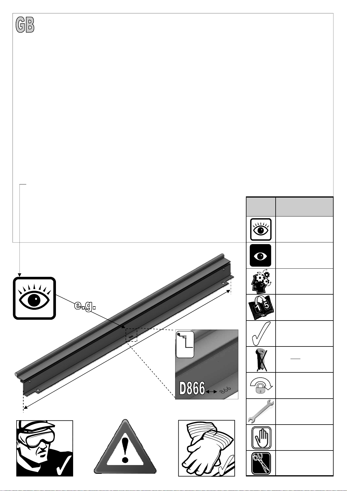
PARTS LIST Most components should have a ‘D’ code punched into their metal surface. Identify and separate all like for like components
prior to assembly. The ‘parts list’ also separates parts into the various sections 1 - 12 shown below. Parts can also be identi-
fied by their profile pictures and stated lengths etc..
B
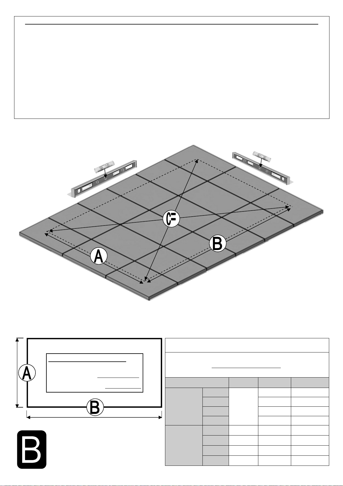
BASE Base dimensions and recommendations. Ensure that your base is level as this will make assembly of the building, especially
the glazing of the roof much more straight forward. Please be aware that the hinge door on your greenhouse opens inwards,
make sure that there will be no interference between the door and the foundations.
P PREPARATION Tools required. IMPORTANT: Use WD40 or similar in the glazing bar channels and insert the black glazing rubber prior to
frame assembly.
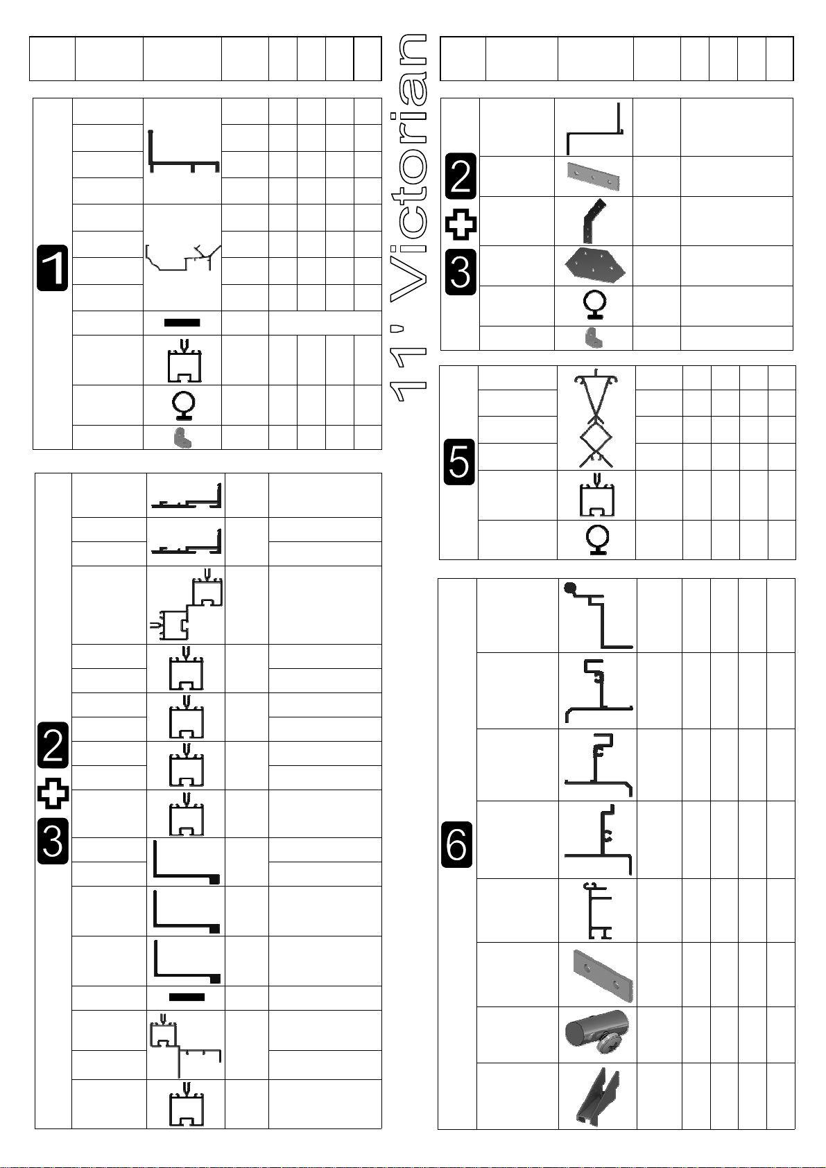
1
SIDES Take the side glazing bars ‘D066’ with the rubber inserted and the diagonal braces ‘D103’, use 10mm bolts to join them to the
gutter and 15mm bolts to the cills (note how the head of the bolt slides into each glazing bar during construction). Please also
remember to slide in your 22mm bolts for attaching the decorative eave spandrels ‘DV100’ in section 5.
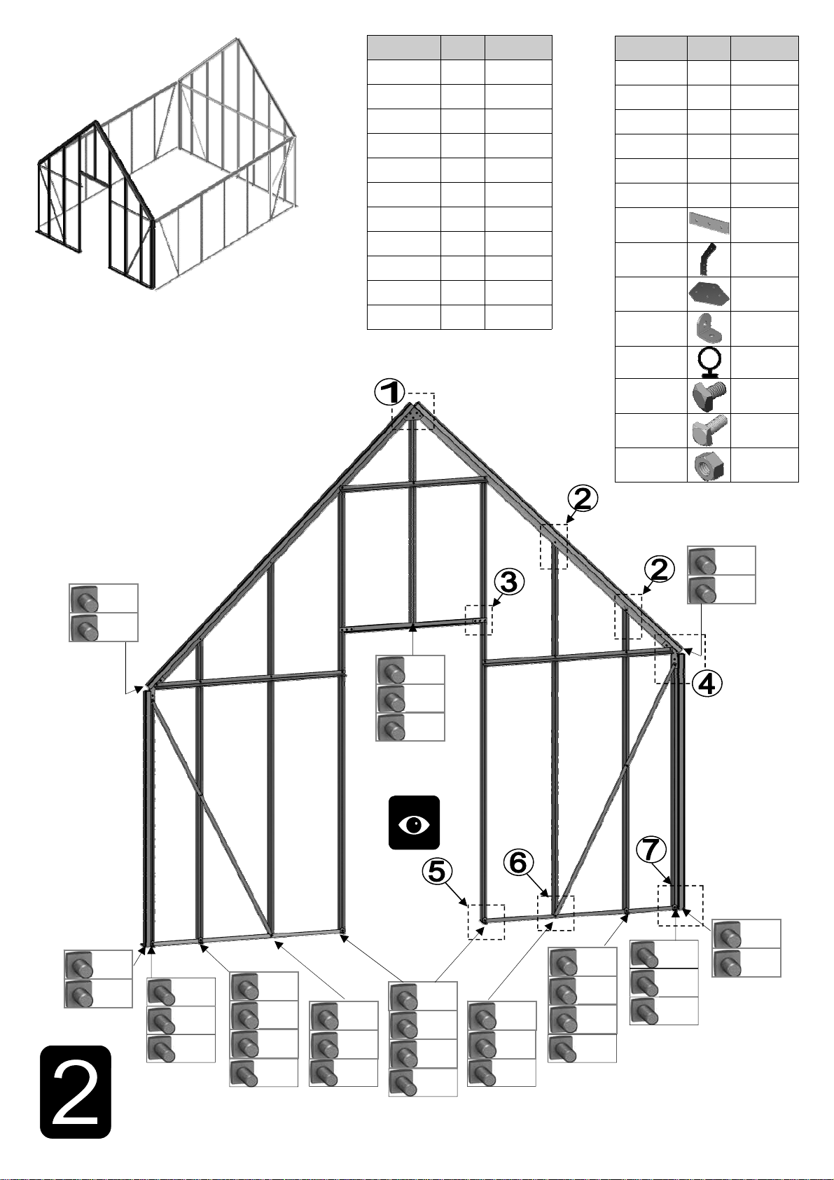
2 FRONT Again insuring that the gable framework is rubbered-up follow the diagrams to assemble each end of the building. Make sure
that you have inserted the extra bolts utilised in sections 4 and 5. On the roof and side corner bars not every rubber channel
will require rubber unless it is to be utilised in a partition (see separate manual and section P).
3 REAR
4 JOINING THE
FOUR SIDES Take the two sides (1) and both gables (2 & 3) and join them together on your base. It is a good idea to tie some ladders to
the sides to support them if you do not have anyone to hold them for you.
5
LOUVRE They attach to the building during the glazing process (8) like a piece of glass with a black separator above and below them.
If you are fitting an optional auto-louvre then you need to carefully drill (3mm bit) out the rivets which mount the handle to the
frame. You can then either utilise those holes or create more to mount the unit.
6
ROOF
Attach the ridge and then the rubbered-up roof bars ensuring that they are fully butted up to the ridge and down onto the gut-
ter. Attach your cresting before you glaze the building to give yourself more room to work. Utilise the 22mm bolts slid into the
side (section 1) and roof bars to attach your DV100 and DV101 spandrels. On longer models you may need to carefully prop
up the roof and tie the sides together to keep the ridge and gutters straight (i.e. not sagging or bowed) until the building is fully
glazed.
7a VENT Once the vent is glazed add silicone to the vent sides and top. Stand the vent/s on their hinge (vent top) and then leave the
silicone to set.
7b VENT SLAM The slam bar ‘D079’ can be moved up and down between the roof glazing bars so that it can be butted down onto the pane of
glass beneath, the autovent will be attached to it later on (9).
8
GLAZING
Layout the bar cappings and covers around the building like a sundial checking that all is present and correct. You can also
place the roof cappings in the gutters so they are closer to hand. The glass in the sides has to bevel on the black separator
strip which is on top of the 305mm high glass base panels. This bevelling action allows the glass to tuck underneath the gut-
ter canopy. Use the capping and the self tapping screws to then hold the glass in place. The covers then enclose the screw
heads giving a neat finish. It is a good idea to glaze two roof sections first to ensure the building is square followed by two
side sections to ensure the building isn't leaning.
IMPORTANT: On the roof sections please make sure that you place a screw around 25mm / 1” from the bottom of
each capping strip (create a hole in the plastic if required) and that the screws are nice and tight to avoid any glass
slippage.
9 VENT
ATTACHMENT Take the assembled vent and slide the vent hinge ‘D866’ into the end of the ridge allowing the vent the pivot open and
closed. Vent stops go either side of the vent to stop any lateral movement (so insert stop / vent / stop). Attach the Bayliss XL
autovents.
10 DOOR
ATTACHMENT Your door comes pre-constructed and locked minus the handles and their pivot pin but now it needs to be mounted to the
front end of your building. Utilise the ‘DV522’ plates and twist in crop headed bolts to join the door and its frame to the build-
ing (pinch the door frame against your long front verticals whilst tightening your ‘DV522’ plates to ensure that there is no gap).
If you are struggling to eradicate the gap between the door frame and verticals then some silicone can be carefully applied to
the area to create a vertical seal. Be careful not to lock yourself in the building and to avoid damage do not open the door
until it is attached to the front gable. Getting the door to swing perfectly without dropping or rubbing on the ground may re-
quire some small but vital adjustments. You may also need to insert a packer underneath the door frame hinge to increase
ground clearance. Part ‘DV275’ canopies the door frame top hiding the clearance space at the top of the door. The door can
only be made to swing inwards.
IMPORTANT: Please do NOT let the door slam open or closed as it is likely to cause damage to the door and the frame.
Please twist the handle to open and close. Please also be aware that your door KEYS (3 provided) are unique to the building
so they should not be stored together.
11 ANCHORING
DOWN Now that the greenhouse is finished and the door and vent/s are operating without interference then you need to anchor the
building down using 2” rawl plugs and screws. Use a 7mm masonry bit in a hammer drill to create the holes.
12 FINISHING
TOUCHES Now that the main body of the structure is complete you can add; downpipe fittings, eave bungs, gutter stop ends. It is also
important to carefully apply some silicone to the internal eaves corners and external and internal ridge corners to minimise
the chance of water entering the structure.
13 OPTIONAL
SHELVING
Robinsons integral cantilever staging and shelving attaches to the inside of the greenhouse frame using either square head
bolts (insert four into each side glazing bar ’D066’ during construction of the sides (1)) or rectangular ‘crop head’ bolts which
can be fitted retrospectively (both sets of bolts accompany the shelving/staging). This system allows the height of either the
staging or the shelf to be set at an operator specific height. Commonly the staging brackets are set 900mm from the cills
though you can alter this to suit the end user/s. The aluminium shelf / staging slats come in two lengths; (4’):1240mm ‘D2002’
and (6’):1860mm ’D2003’. These slats can combine to create any length of staging required, i.e. 4’+6’ = 10’ etc...
14 OPTIONAL
STAGING