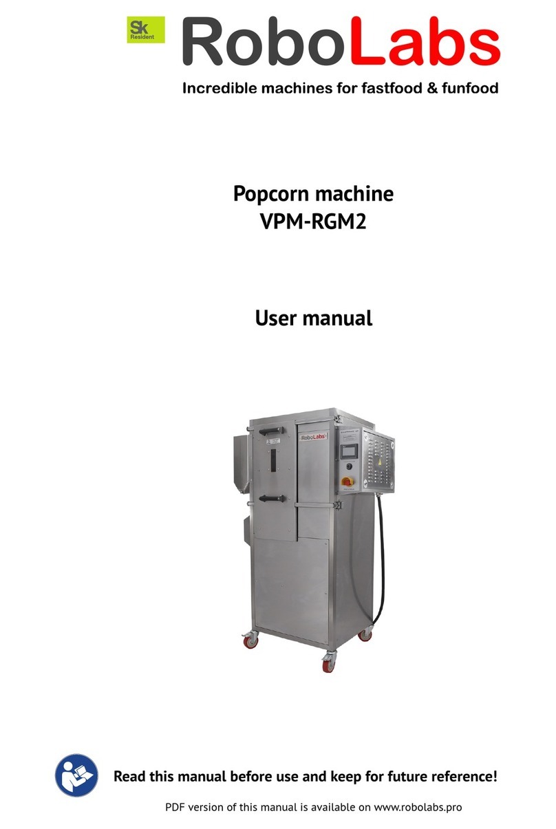
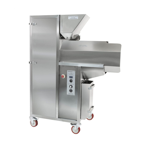
RoboLabs Vortex Popcorn Robopop 60 Operating manual

Vortex popcorn machine
Robopop 60
(VPM-RM4)
Technical service manual
Read this manual before use and keep for future reference!
PDF version of this manual is available on www.robolabs.pro

Safety requirements
This is the safety alert symbol. It is used to alert you to potential physical injury haz-
ards. Obey all safety messages that follow this symbol to avoid possible injury or death.
DANGER
•THIS MANUAL IS FOR SKILLED TECHNICIANS ONLY!
•DO NOT open electric panels unless you are qualified for this.
•Electric shock hazard! High voltage inside electric panel. DO NOT touch bare
terminals and/or wires.
•ALWAYS unplug the machine before servicing, unless you need it to be energized
for performing setup procedures.
WARNING
•Burn hazard! Some parts of machine are very hot. Wait until machine is cooled
down before working with those parts.
WARNING
•ALWAYS wear eye protection while servicing this equipment to avoid possible
injury.
Technical service manual 2692 1

Contents
1 Backlight 3
2 VFD (inverter) 4
3 Fiber amplifier 5
4 Voltage control relay 6
5 Temperature limiter 7
6 Chamber deep cleaning 8
7 Heating circuit 9
7.1 Heatingelementscheck..................................... 9
7.2 Solid-staterelayscheck..................................... 10
7.3 Contactorcheck ......................................... 10
7.4 Temperature limiter output check . . . . . . . . . . . . . . . . . . . . . . . . . . . . . . . 11
Technical service manual 2692 2

1 Backlight
DANGER
•Electric shock hazard! Unplug the machine before servicing.
WARNING
•Burn hazard! Wait until machine is cooled down.
1
2
3
2
Figure 1: Backlight
1. Unplug the machine. Wait until it cools down.
2. Open the chamber. Locate the backlight (Fig.1).
3. Remove two screws that holds protective screen (1); take the
screen o. If it is stuck, carefully insert flat screwdriver under
the metal frame of the screen and turn it gently to detach the
screen.
4. The lightbulb (3) is held by two spring loaded sockets (2). Take
the bulb firmly and press towards one of the socket (2), release
the opposite end of the bulb from the socket, and finally release
the second end of the bulb and take the bulb out.
5. DO NOT TOUCH THE NEW BULB WITH BARE FINGERS! Skin
grease will significantly reduce the lifetime of the bulb. Use a
soft clean cloth or gloves to take and install the new bulb.
6. Insert the bulb in the sockets in the same way.
7. Close the protective screen and fix it with screws.
8. Close the chamber.
Technical service manual 2692 3

2 VFD (inverter)
DANGER
•Electric shock hazard! High voltage inside electric panel. DO NOT touch bare
terminals and/or wires.
Figure 2: VFD control panel
NOTE 1: VFD setup must be performed only when the
drive is stopped.
NOTE 2: After setting parameter 02.00 to 9, VFD
displays End , and gets back to the main indication
mode. After this, continue setup process from parameter
00.03.
Parameters changing procedure
1. Locate the VFD control panel, see Fig 2.
2. To change or view parameter value, press , the display shows 00.__
3. Press or to choose the first two digits of the parameter (for example, 02).
4. Press again, display shows 02.00 .
5. Press or to choose the second two digits of the parameter, for example, 02.11 .
6. Press again to see the current value of the parameter. Change value, if needed, with
or .
7. Press to confirm and save the new value, the display shows End .
8. Press to return back to the previous level of selection or to the main mode.
Parameter Value Description
00.02 9 Settings initialization
00.03 0 Start-up display selection
01.00 70.00 Maximum output frequency
01.16 4 Auto accel/decel
02.00 3 Source of first master frequency command: RS-485
02.01 4 Source of first operation command: RS-485
02.04 0 Motor direction control
02.07 1 Up/Down mode
02.09 0 Source of second frequency command
02.10 1 1st and 2nd master frequency command combination
02.11 40.0 Keypad frequency command
09.00 5 VFD communication address
09.01 1 Transmission speed: 9600 bps
09.02 3 Transmission fault treatment:keep operating
09.04 1 Communication protocol: ASCII 7, E, 1
Technical service manual 2692 4

3 Fiber amplifier
DANGER
•Electric shock hazard! High voltage inside electric panel. DO NOT touch bare
terminals and/or wires.
Figure 3: Paper screen
1
2
3
4
5
Figure 4: Fiber amplifier
1. Put a folded sheet of white paper in the chamber as shown on Fig.3, so the light ray of the sensor
is screened.
2. Locate fiber amplifier in electric panel, see Fig.4.
3. If operation indicator (1) is o, go to the next step. If indicator (1) is on, rotate the screw (3)
counter-clockwise, until indicator (1) turns o.
4. Set timer switch (4) to OFF.
5. Set operation mode selector (5) to L.
6. Slowly rotate the screw (3) clockwise until indicator (1) turns on.
Technical service manual 2692 5

4 Voltage control relay
DANGER
•Electric shock hazard! High voltage inside electric panel. DO NOT touch bare
terminals and/or wires.
1
2
34
5
11
14
Figure 5: Voltage control relay
Voltage control relay (Fig.5) is intended to protect the ma-
chine from improper connection and from voltage devia-
tions in the service grid.
Set-up procedure
1. Locate the relay, see Fig.5
2. Set the knob (1) at 260 V.
3. Set the knob (2) at 180 V.
4. Set the knob (3) at 2 s.
LED indicators status
green on, yellow on
Voltage is ok. Check if mains voltage present at terminal (14).
green on, yellow blinks
Voltage is beyond allowed range. Check the voltage in the mains.
green flashes, yellow flashes
Voltage exceeds both high and low limit because of improper set up.
Technical service manual 2692 6

5 Temperature limiter
DANGER
•Electric shock hazard! High voltage inside electric panel. DO NOT touch bare
terminals and/or wires.
Figure 6: TC4SP panel
TC4SP unit (Fig.6) has three setting groups: 1st setting group,
2nd setting group, and SV setting group (the main indication mode).
The settings must be changed in the same order as they appear in
the list. Note that after changing In-t (temperature sensor type)
or UnI-t (temperature unit) values, parameters H-Su , L-Su , AL1 ,
AL2 , AHYS must be set again. The regulator has more parameters
than listed below; if you see a parameter not from the list, skip it and
move to the next one.
Parameters changing procedure
1. To access the 2nd group of parameters press and hold for 4
seconds; once display reads PAr2 , release .
2. To access the 1st group of parameters, press and hold for 2
seconds; once display reads PAr1 , release .
3. Press to go through the parameters. Press to see current
value of the parameter.
4. Press or to change the value.
5. Press to move to the next parameter.
Group Param Value Meaning
2nd LoC oFF Unlock all settings for changing
2nd In-t YCA Temperature sensor type
2nd L-Su 250 SV low-limit value
2nd H-Su 400 SV high-limit value
2nd C-nd onoF Control type
2nd oUt rLY Control output
2nd AL-1 An1._ AL1 alarm operation mode
2nd AHYS 50 Alarm output hysteresis
1st AL1 0 AL1 alarm temperature
1st HYS 50 Hysteresis
2nd LoC LoC2 All settings locked, except SV
SV SV 350 Default temperature
Technical service manual 2692 7

6 Chamber deep cleaning
Over time, corn dust and husk might be accumulated in hidden areas of the chamber. This negatively
aects normal airflow in the corn supply tube. If corn supply tube clogged with popcorn frequently,
then it is necessary to clean those areas of the chamber.
1
2
3
4
4
5
1
6
7
Chamber section view
Figure 7: Chamber deep cleaning
1. Open the chamber.
2. Unscrew two bolts (5) (here and below see Fig.7).
3. Take the bae (4) out from the chamber.
4. Unscrew four bolts (6) that holds perforated bowl (1) in place.
5. Take the perforated bowl (1) out from the chamber.
6. Thoroughly clean griddle (2) and end of the corn supply tube (3).
7. Assemble in back order. HINT: it is recommended to hold the perforated bowl by the central M5
screw (7) while putting it back to place.
Technical service manual 2692 8

7 Heating circuit
T1
L1
LED
A1
A2
L1
76
L2 L3
75
Y
135
246
T2
L2
OUT
Figure 8: Elements of heating circuit
7.1 Heating elements check
1. Unplug the machine and see Fig.8.
2. Measure the resistance between T1 and T2; it must be 20-22 Ohms.
(a) If it reads OL, then check heaters wiring, busbars, and the heaters directly.
(b) If it reads 30-31 Ohms, then one of the heating elements is fault, see the next steps.
3. Measure the resistance between T1 and 6; it must be 10-11 Ohms.
(a) If it reads OL, then check heaters wiring, busbars, and the heaters directly.
(b) If it reads 20-22 Ohms, then one heating element is fault. Locate and replace it.
4. Measure the resistance between T2 and 6; it must be 10-11 Ohms.
(a) If it reads OL, then check the heaters wiring, busbars, and the heaters directly.
(b) If it reads 20-22 Ohms, then one heating element is fault. Locate and replace it.
Technical service manual 2692 9

7.2 Solid-state relays check
1. Turn the machine on.
2. Make sure LED indicators are o.
3. Check to see if the mains voltage (208 Vac) presents at L1.
(a) If negative, perform Contactor check, see below.
(b) If Contactor check positive, then disconnect the machine and check the consistency be-
tween L1 and 1. Tighten the terminals or replace the wire if required.
4. Check to see if the mains voltage (208 Vac) presents at L2.
(a) If negative, perform Contactor check, see below.
(b) If Contactor check positive, then disconnect the machine and check the consistency be-
tween L2 and 3. Tighten the terminals or replace the wire if required.
5. Measure the voltage between T1 and L1; it must be 208 Vac. If it reads 0–5 Vac, and LED indicator
is o, and the display of temperature limiter reads increasing values, then the relay is out of order;
replace it.
6. Measure the voltage between T2 and L2; it must be 208 Vac. If it reads 0–5 Vac, and LED indicator
is o, and the display of temperature limiter reads increasing values, then the relay is out of order;
replace it.
7. Run any program (Butterfly or Mushroom).
8. Check T1 to L1 voltage. Whenever LED is on, it must be 0–5 Vac. If it reads 208 Vac while LED is
on, then relay is out of order; replace it.
9. Check T2 to L2 voltage. Whenever LED is on, it must be 0–5 Vac. If it reads 208 Vac while LED is
on, then relay is out of order; replace it.
7.3 Contactor check
1. Turn the machine on. See Fig.8.
2. Make sure OUT indicator is on.
3. Check A1 to A2 voltage; it must be 208 Vac. Otherwise do the following.
(a) Unplug the machine, and check A1 to Q3 for open circuit. Tighten the terminals or replace
the wire if required.
(b) Unplug the machine, and check A2 to 76 for open circuit. Tighten the terminals or replace
the wire if required.
(c) Check the Temperature limit output check, see below.
4. Check 1 and 3 voltage; it must be 208 Vac.
5. Check 1 and 5 voltage; it must be 208 Vac.
6. Check 3 and 5 voltage; it must be 208 Vac.
(a) If no mains voltage presents at 1, 3, 5 then unplug the machine, trace and locate the wires
fault.
7. Check 2 and 4 voltage; it must be 208 Vac.
8. Check 2 and 6 voltage; it must be 208 Vac.
9. Check 4 and 6 voltage; it must be 208 Vac.
Technical service manual 2692 10

(a) If no mains voltage presents at 2, 4, 6 then unplug the machine, open the plastic hatch
covering armature plunger Y; use a suitable tool to press the plunger inside the contactor.
While pressed terminals 1,3,5 must be closed to 2,4,6, respectively. If the plunger cannot
be moved inside smoothly, or doesn’t close the terminals, the contactor must be replaced.
7.4 Temperature limiter output check
1. Check to see if the mains voltage presents at 75. If not, then trace and locate the wire fault.
2. Check to see if the mains voltage presents at 76 whenever OUT indicator is on. If not, then
temperature limiter must be replaced.
Technical service manual 2692 11
This manual suits for next models
1
Table of contents
Other RoboLabs Kitchen Appliance manuals

RoboLabs
RoboLabs ROBOJETFLOSS User manual

RoboLabs
RoboLabs ROBOJETFLOSS User manual

RoboLabs
RoboLabs MINI ROBOPOP 25 User manual

RoboLabs
RoboLabs TWISTER-M2 User manual

RoboLabs
RoboLabs ROBOMIX MINI User manual
RoboLabs
RoboLabs VPM-RGM2 User manual

RoboLabs
RoboLabs ROBOJETFLOSS ACB-09-120 User manual

RoboLabs
RoboLabs Grand Robopop 220 User manual
RoboLabs
RoboLabs Robopop 75 User manual

RoboLabs
RoboLabs ROBOPOP 60 User manual