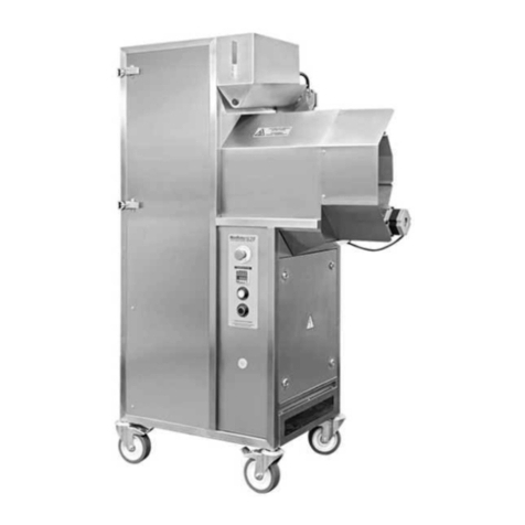
RoboLabs VPM-RGM2 User manual

Popcorn machine
VPM-RGM2
User manual
Read this manual before use and keep for future reference!
PDF version of this manual is available on www.robolabs.pro

Safety requirements
This is the safety alert symbol. It is used to alert you to potential physical injury
hazards. Obey all safety messages that follow this symbol to avoid possible injury
or death.
DANGER
•Not grounded equipment can cause electric shock. Power outlet MUST HAVE
PROPER GROUNDING to avoid electric shock.
•Using excessive water during cleaning can cause short circuit and electric
shock. DO NOT USE excessive water or water jet for cleaning. DO NOT SPILL
water on electric panels or parts.
•ALWAYS unplug equipment before cleaning or servicing.
•No user serviceable parts inside. DO NOT OPEN electric panel unless you are
qualified for this.
WARNING
•DO NOT USE other crops than corn with this machine.
•DO NOT NOT LEAVE running machine UNATTENDED.
WARNING
•During operation some surfaces might be hot. Direct contact can cause burn.
DO NOT TOUCH.
WARNING
•IMPROPER INSTALLATION, ADJUSTMENT, ALTERATION, SERVICE OR MAIN-
TENANCE CAN CAUSE PROPERTY DAMAGE, INJURY, OR DEATH. Read and un-
derstand this manual before use.
•ONLY INSTRUCTED PERSONNEL is allowed to operate the equipment.
1

Contents
1 General information 3
1.1 Technicalspecifications .................................... 3
1.2 Manufacturerdetails...................................... 3
1.3 Qualitycheck .......................................... 3
1.4 Warrantyobligations...................................... 4
1.5 Transportationandstorage .................................. 4
1.6 Ambientconditions....................................... 4
2 Assembling and installation 5
2.1 Deliveryset ........................................... 5
2.2 Assembling ........................................... 5
2.3 Powerrequirements ...................................... 5
2.4 Ventilationrequirements ................................... 5
3 Design and principle of operation 6
3.1 Maincomponents........................................ 6
3.2 Controls ............................................. 7
3.3 Stagesofoperation....................................... 8
4 Intended use 9
4.1 Operatingorder......................................... 9
4.2 Chamberclogging ....................................... 11
5 HMI interface 12
5.1 Initialscreen .......................................... 13
5.2 Testingscreen.......................................... 14
5.3 Settingsscreen ......................................... 15
5.4 Operationprocessscreens................................... 16
5.5 Processmonitoringscreen .................................. 17
5.6 Temperaturegraphscreen................................... 18
6 Maintenance and cleaning 19
6.1 Dailycleaning.......................................... 19
6.2 Weeklycleaning ........................................ 19
6.3 Conservation .......................................... 19
2

1 General information
VPM-RGM2 is a hot-air popcorn making machine (hereinafter “the machine” or “the popper”, or “the
equipment”). It can process both Butterfly and Mushroom popcorn kernels.
Commercial use only.
1.1 Technical specifications
Throughput up to 100 kg/h
Rated voltage 400 VAC
Rated frequency 50 Hz
Rated current 42 A
Dimensions (LxWxH) 1220x810x1930 mm
Net weight 300 kg
Airborne acoustic noise less than 70 dBA
Material stainless steel
1.2 Manufacturer details
RoboLabs Ltd.
11 Industrialnaya Street, Tver, 170100 Russia
Technical support:
Email: suppor[email protected]
Phone: +7 495 956 4000
1.3 Quality check
VPM-RGM2
model serial no.
The equipment is made with accordance to mandatory requirements of the state
standards, actual technical documentation, and approved for use.
QC Engineer
STAMP HERE
signature full name
DD.MM.YYYY
3

1.4 Warranty obligations
The manufacturer guarantees trouble-free operation of the equipment during 12 months from the
date of receiving the equipment by a dealer (in accordance with transport documentation); or, in
case of purchase directly through Trapeza LLC or RoboLabs Ltd., from the date of purchase, given
that terms of using, transportation, and storage are met.
The warranty repair is performed upon presentation of this manual and filled warranty card with
the seller’s seal and the date of sale. Technical specifications of the equipment can be changed
by manufacturer at any time due to improvements and/or other reasons. Technical specifications
stated in this document are intended to act as a reference point, which is necessary to evaluate
suitability of the equipment for the customer’s needs, and are not the subject of warranty policy.
The information stated in this document has been thoroughly checked and considered as accurate
one; nevertheless, the manufacturer is not responsible for any typographical errors or misprints.
Due to constant improvement of the equipment, technical specifications are subject to change without
prior notice!
1.5 Transportation and storage
The equipment may be transported by any kind of covered vehicle, in accordance with transportation
rules for this kind of vehicle. Ambient temperature during the transportation and storage must be
between minus 25◦C and plus 55◦C.
1.6 Ambient conditions
This equipment is designed to be operated at the ambient temperature from +5◦C to +40◦C (+41◦F
to +104◦F) and relative humidity not more than 45% at 40◦C (104◦F) while using at altitudes not
exceeding 1000 m over the sea level. The temperature decreasing is related to RH increasing, for
example, 90% of RH at 20◦C (68◦F). This equipment MUST NOT be exposed to precipitations of any
kind (rain, snow and so on).
4

2 Assembling and installation
2.1 Delivery set
1x Popcorn machine
1x Electric panel key
1x Cleaning brush
1x Spare halogen lamp
1x Documentation set
2.2 Assembling
1. Unpack the machine carefully.
2. Check the delivery set.
3. Remove protective film from all surfaces.
4. Wipe all surfaces with a clean soft cloth dampen with mild soap. Then remove soap residues
with a clean cloth dampen with water. Let it dry.
5. Lock all four swivel casters.
NOTE 1: Each machine is tested at the factory with corn, some amount of corn kernels might be
found inside the chamber.
NOTE 2: If equipment was stored below 0 ◦C, keep it at normal room temperature not less than
3 hours before the first start.
2.3 Power requirements
DANGER
•Power outlet MUST HAVE PROPER GROUNDING to avoid electric shock.
•If supply cord damaged, it must be replaced by manufacturer, service agent,
or skilled person in order to avoid hazard.
•Connections must be done BY SKILLED ELECTRICIAN ONLY.
•
Equipotential bonding wire (up to 10 sq.mm) shall be connected
to screw terminal on the base frame marked with IEC 60417-
5021 sign:
Machine requires 5-wire 3 phase 400 VAC 50 Hz power supply. Use the 63 A 400 V 50 Hz 3+N+PE
connector in accordance with IEC 60309 standard. Short-circuit current rating for the machine is
6 kA.
2.4 Ventilation requirements
A ventilation hood measuring at least 1200x1200mm must be provided above the machine, with a
minimum capacity of 2500 cu.m/h.
5

3 Design and principle of operation
3.1 Main components
Figure 1: Main components
Main components of machine is represented on Fig. 1.
Motor with turbine causes air circulation inside the machine. Air goes from the turbine to the
working chamber, then to the heating elements area, where it is heated, and finally goes back to
the turbine.
Popcorn kernels is loaded in the corn bin with feeder, see Fig. 2. The feeder consists of feeding
motor and an auger inside the bin. The motor drives the auger, which pushes corn in the chamber.
Fixed guard covers the rotating auger to avoid direct contact.
Corn bin optical sensor trips whenever the bin becomes empty. Once the sensor is tripped, the
machine notifies an operator that the bin must be refilled.
Figure 2: Corn bin with feeder
6

Figure 3: Working chamber
From the corn bin, corn kernels goes to
working chamber, through the corn supply
tube, see Fig. 3.
Perforated bowl has many holes of spe-
cial shape, which cause air vortex inside the
chamber as airflow goes through the bowl.
Due to air vortex, corn kernels are constantly
moving inside the chamber around center of
the bowl. Kernels eventually pop, and then
being evacuated from the chamber by the
means of air flow, through the chamber out-
put.
Baffle divides the chamber for the area
where corn kernels are being heated up, and
the output areaz.
Mesh screen protects internal cavities (in-
cluding heating elements area) from popcorn
dust and scrap accumulation.
Temperature sensor constantly measures temperature of the air in the chamber. Optical sensor
controls corn movement inside the chamber. Machine will not start next batch until a batch of corn
is completely processed, thus avoiding chamber clogging with corn kernels and popcorn.
Chamber lamp illuminates the chamber, so an operator can visually control the process through
the observation port in the chamber door.
3.2 Controls
Figure 4: Control panel
Control panel represented on Fig. 4.
HMI panel is used to control the machine,
change the parameters of operation, and so
on.
START push button turns the machine
on.
Emergency stop switch shuts down the ma-
chine immediately at any moment.
7

3.3 Stages of operation
Whenever the machine is turned on, it is in one of the following stages of operation.
Standby mode
Once the machine is turned on, the HMI panel boots up, and the machine is waiting for operator
action. At this moment operator can:
1. Check and adjust parameters of the machine, and also reset to default.
2. Test corn feeder, turbine.
3. Start popcorn production process.
Heating stage
Once operator initiates the production process, the machine starts to heat up air in the chamber.
Upon reaching the set value temperature the machine automatically starts popping process.
Popping stage
Machine processes corn kernels cycle by cycle. Each cycle consists of three parts:
1. Purge – turbine is accelerated in order to blow out everything left in the chamber: un-popped
kernels, dust and other scrap.
2. Feeding – corn kernels pushed into the chamber.
3. Popping – corn kernels are heated up in the chamber, eventually evacuated as they pop.
Pause stage
Whenever the operator initiates pause, the machine processes current batch of corn, and then stop
feeding next batches of corn. The temperature in the chamber is maintained at the set value.
Popping process can be resumed at any time.
Cooling stage
The machine needs to be cooled down before turning the turbine off. Whenever the operator ini-
tiates cooling mode, heating elements are de-energized; but the turbine keeps running, cooling
down the machine. Once temperature drops low enough, the turbine stops and the machine can be
turned off.
8

4 Intended use
DANGER
•DO NOT USE if power cord, or plug, or wall outlet are damaged, and also if
chamber lamp is blown out.
WARNING
•DO NOT USE emergency stop switch for routine stop. Doing so might lead to
machine failure and smoke formation. Use only in case of emergency.
•MAKE SURE ALL FOUR SWIVEL CASTERS IS LOCKED. Unlocked swivel casters
might lead to accidental move of the machine.
•DO NOT NOT LEAVE running machine UNATTENDED.
•DO NOT OPERATE with blown chamber lamp.
WARNING
•Outer surfaces of chamber, corn supply tube, and corn bin might be very hot
during operation. DO NOT TOUCH the hot surfaces.
•Hot air comes out from the corn supply tube (see Fig. 2) during machine
operation. STAY CLEAR.
WARNING
•MAKE SURE FIXED GUARD IS SECURED on its place (see Fig. 2). Touching
rotating auger might cause hand or finger injury.
4.1 Operating order
1. Make sure the chamber is clean. If not, clean the chamber.
2. Make sure the receiving device (e.g. sifter VPM-RGSM3EU) is running.
3. Fill the corn bin with corn kernels.
4. Press START push button on the control panel. Wait until HMI display shows the start screen.
The yellow reading with PV means process value temperature. The white reading of the
temperature represents the set value:
9

5. Press
v 1.1
to start heating up. The display reads HEATING:
6. Once warmed up, the machine begins to execute production cycle. Each stage of the cycle is
represented as ’FEEDING’, ’POPPING’ and ’PURGE’.
7. To suspend the operation, press . To resume, press .
8. To finish the operation, press and hold until ’COOLING’ message appears:
9. To resume popping, press and hold
10. Wait until the initial screen appears. Press and hold to shut down the machine.
10

4.2 Chamber clogging
DANGER
•NEVER USE WATER in case of smoke formation.
WARNING
•DO NOT OPEN in case of smoke formation.
•DO NOT USE fire extinguishers. Machine is made of stainless steel, as long
as chamber is closed, popcorn won’t get fire.
The chamber may be clogged due to the following reasons:
•Low quality corn. Un-popped kernels are accumulating in the chamber and cannot be evacu-
ated, which causes weakened airflow, and eventually chamber clogging and smoke formation.
•Power supply issues (voltage drop, power cut-off) or actuating Emergency stop switch that
causes turbine stop, which leads to steep temperature rise inside the chamber, and eventually
chamber clogging and smoke formation.
IN CASE OF CHAMBER CLOGGED OR SMOKE FORMATION, DO THE FOLLOWING:
1. UNPLUG the machine.
2. WAIT until machine COOLS DOWN.
3. Open the chamber and thoroughly clean inside.
4. If corn supply tube is clogged with corn kernels and popped popcorn, use the cleaning brush
from the delivery set to remove popcorn stuck in the tube and to clean the tube.
11

5 HMI interface
The HMI interface consists a range of screens (see Fig. 5), that provide ability of controlling and
monitoring of machine operation, changing parameters of operation and settings of the machine,
and also testing of the machine.
LOW CORN
POPPING
HEATING
FEEDING
POPPING
PURGE
COOLING
PAUSE
corn auger
rpm / time 250 20.0
6.00
freq. increase
start / step 30.0 15.0
add. purge
chamber freq. 20.0
time preheat
ON / OFF 60.0 60.0
count
popcorn 15
EN
154.2
PV
DEFAULT
operation
time 14.2
T: 203.5/210.0DT: 30.0
CM: 100A
DT: 1200
1200
OFF
KP:
KI:
KD:
120
10
50
CLOGGING
AUTO
210.0
27.50
27.50 PV
203.5 PV 15.6
wait... heating
paused machine
popping timer
purge chamber timer
clogging
batch counter 12
corn auger timer
T
v 1.1
12.30.0
TEST
LOW CORN
COOLING
210.0
AL1
ERROR VFD
CLOGGING
wait... popping
210.0
9.3
ATTENTION!
MOTOR ERROR
popping
time
add. popping
freq.
purge
chamber time
180.0
10.0
extra heat
time 60.0 CN: 42/15
11:33
11:30 11:3211:28
PID
201.5
PRESS AND HOLD 1s
HOLD 1s
HOLD 1s
HEATING
210.0
123
456
789
0 .
Enter
ESC
MIN: 190.0
MAX: 250.0
210
154.2
PV
v 1.1
TEST
ATTENTION!
CHECK
OPT. SENSOR
IN CHAMBER
ATTENTION!
TEMPERATURE
SENSOR ERROR
v 1.1v 1.1
v 1.1
popping
time
v 1.1
v 1.1v 1.1
v 1.1
Figure 5: HMI screens flowchart
12

5.1 Initial screen
The initial screen (Fig. 6) appears first after machine turned on.
Figure 6: Initial screen Figure 7: Error messages
v1.1 – version of software.
154.2 PV – current temperature in the chamber.
v 1.1
– press to start popping process.
– press to enter the testing screen.
– press and hold 1 sec to turn the machine off.
If chamber temperature sensor or chamber optical sensor needs to be checked, the machine will
show the error messages, see Fig. 7.
13

5.2 Testing screen
Figure 8: Testing screen
Operation time 14.2 – Total operation time in hours.
LOW CORN – Corn bin sensor indicator. Yellow when tripped.
CLOGGING – Chamber optical sensor indicator. Yellow when tripped.
DEFAULT – Reset all settings to default (password required, see below).
– Turbine ON/OFF button. Press once to start. Press again to stop. Reading in the right
low corner adjacent to the sign is the turbine speed in Hz.
– Auger start button. Press once to start a cycle of feeding. Reading in the right low corner
adjacent to the sign is the auger cycle timer.
– Press to proceed to the settings screen.
– Press to enter password (2325) required to reset the settings.
– press to return to the previous screen.
14

5.3 Settings screen
Figure 9: Settings screen
Corn auger rpm/time – Speed of corn auger and duration of feeding cycle, in seconds.
Popping time – duration of popping stage, in seconds.
add.popping freq. – increment for turbine speed during popping stage, in Hz.
freq.increase start/step – the turbine speed is changed from the basic speed set, see Fig. 13,
to the basic speed plus add.popping freq. The speed is being changed gradually, in four steps. The
first value (30 seconds) defines the moment when the turbine begins to accelerate (counting from
the moment the feeder stopped). The second value (15 seconds) defines duration of each step.
purge chamber time – duration of purge stage, in seconds.
add. purge chamber freq. – increment for turbine speed during purge stage in Hz.
time preheat ON/OFF – Defines the heaters operation during heating up stage. For example
60/60 means that heaters are on for 60 seconds, then are off for 60 seconds.
extra heat time – forced heating time. In the beginning of each cycle heaters are operated at
full rate, without PID-regulation, this helps to avoid significant temperature drop during the cycle.
count popcorn – count threshold for optical sensor in the chamber.
EN – press to change the language of the interface (RU/EN).
– press to return to the previous screen.
15

5.4 Operation process screens
Figure 10: Operation process
screen
Figure 11: Temperature change
Figure 12: Switch to cooling
LOW CORN – error message (if error condition presents). the
following options are possible:
•LOW CORN – Photoelectric sensor in the corn hopper is
tripped. Refill the hopper.
•VFD ERROR – Turbine drive (VFD) has an error.
•CLOGGING – Chamber optical sensor is tripped.
– indicates that machine is in popping mode. Press
to put machine in pause mode.
– indicates that machine is in pause mode. Press
to put machine in popping mode.
POPPING – current status of operation, the following op-
tions are possible:
•HEATING – the machine is being heated up.
•FEEDING – corn feeding auger operates, loading batch
of corn kernels in the chamber.
•POPPING – corn inside the chamber is being processed.
•PURGE – the machine increases the speed of turbine in
order to remove un-popped kernels, dust and husk from
the chamber, before loading next batch of corn.
•COOLING – the machine is being cooling down.
•PAUSE – the machine does not process corn, but main-
tains the working temperature in the chamber.
210.0 – working temperature set value. Press to change, see Fig. 11. Type the new value
and press ENTER to confirm.
– press to move to process monitoring screen.
– indicates that the machine is not in cooling mode at the moment. Press and hold for 1
sec to switch to cooling mode, see Fig. 12.
wait... popping – indicates that machine needs to finish current production cycle before actual
cooling down.
– press and hold for 1 sec to initiate a cycle of purge. During the purge, the sign becomes
yellow and in the right low corner adjacent to the sign, the purge timer will be shown.
– press and hold for 1 sec to stop cooling process.
16

Figure 13: Process monitoring screen
5.5 Process monitoring screen
210.0 – working temperature set value. Press to change the value.
203.5 PV – current temperature in the chamber.
27.50 – set value for basic turbine speed. Press to change the value.
27.50 PV – current speed of the turbine.
batch counter 12 – batch counter (reset every time the machine is turned off).
15.6 – countdown timer for the stage of the operating cycle that takes place at the mo-
ment. Only shown when machine is in popping mode.
corn auger timer – the name of the stage that takes place at the moment (only when the
machine is in popping mode), including:
•corn auger timer – duration of corn feeding auger operation, in sec.
•popping timer – duration of popping stage, in sec.
•purge chamber timer – duration of purge stage, in sec.
When machine is not in popping mode, the following messages appear here:
•wait... heating – indicates that the machine is in heating mode.
•paused machine – indicates that the machine is in pause mode.
•clogging – indicates that the chamber is clogged.
T
– press to move to the temperature graph screen.
– press to return to the previous screen.
17

5.6 Temperature graph screen
Figure 14: Temperature graph screen
11:33 – Current time.
201.5 – Temperature value at the point where the vertical dashed line intersects the temper-
ature graph. Touch the line and drag left or right to move across the graph.
DT:30.0 – Temperature delta parameter. Defines vertical scale for temperature. For example,
DT:30.0 means that the display fits temperature within the range ±30 ◦C from the set value (middle
line).
T:203.5/210.0 – current temperature in the chamber (203.5), set value (210.0).
CN: 42/15 – current value of popcorn counter (42), threshold value (15). See "count popcorn"
in Settings screen section.
– press to move in the PID regulator screen (password required).
– press to return to the previous screen.
Scrolling bar in the low part of the screen allows to see the temperature graph changing in time.
Time stamps are marked below the graph.
18

6 Maintenance and cleaning
DANGER
•DO NOT USE EXCESSIVE WATER OR WATERJET for cleaning.
•DO NOT SPILL WATER on the machine.
•ALWAYS KEEP power cord plug off the floor and water.
WARNING
•Inner and outer surfaces of the chamber, as well as corn supply tube are very
hot. ALWAYS WAIT until machine COOLS DOWN before cleaning.
CAUTION
•DO NOT USE high alcaline cleaners.
•DO NOT USE sharp items or abrasives for cleaning.
The purpose of maintenance and cleaning is to keep machine in good condition during all the
lifetime and to meet safety requirements.
6.1 Daily cleaning
1. Wipe outer surfaces of the machine with a soft and clean cloth dampened with mild soap.
2. Wipe outer surfaces of the machine with a soft and clean cloth dampened with clear water to
remove soap residues and let it dry.
3. Remove un-popped kernels and debris from perforated bowl, see Fig. 3.
4. Remove dust from internal surfaces of the chamber with the means of soft dry clean cloth.
Avoid hard impact to the optical sensor, see Fig. 3.
6.2 Weekly cleaning
1. Perform daily cleaning procedures.
2. Clean the mesh screen (see Fig. 3) with a suitable brush or a vacuum cleaner.
3. Empty the corn bin.
4. Wipe internal surfaces of the bin with a soft clean cloth dampened with mild soap; then
remove soap residues with a cloth dampened with water. Let it dry.
5. Use the cleaning brush to clean the corn supply tube from the side of corn feeder, and then
from inside the chamber.
6.3 Conservation
If machine is not used for long time, perform all cleaning procedures and pack it.
19
Table of contents
Other RoboLabs Kitchen Appliance manuals
RoboLabs
RoboLabs ROBOMIX MINI User manual

RoboLabs
RoboLabs TWISTER-M2 User manual

RoboLabs
RoboLabs Vortex Popcorn Robopop 60 Operating manual

RoboLabs
RoboLabs ROBOJETFLOSS User manual

RoboLabs
RoboLabs MINI ROBOPOP 25 User manual

RoboLabs
RoboLabs Grand Robopop 220 User manual

RoboLabs
RoboLabs ROBOPOP 60 User manual

RoboLabs
RoboLabs ROBOJETFLOSS User manual
RoboLabs
RoboLabs Robopop 75 User manual
RoboLabs
RoboLabs ROBOJETFLOSS ACB-09-120 User manual