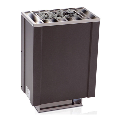
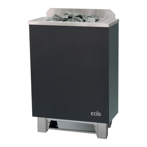
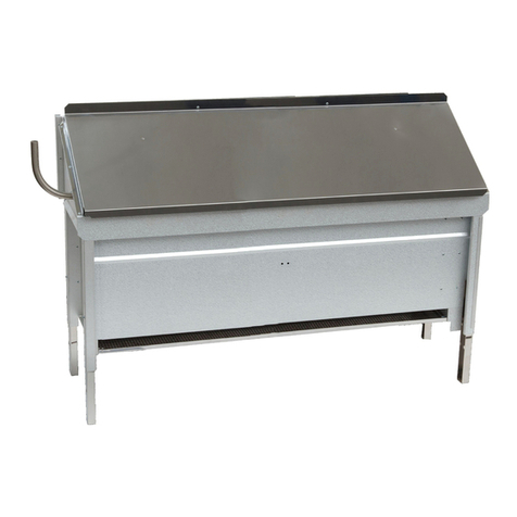
EOS 38.AS Installation guide

Druck Nr. 29342172 / - 44.04 20012552
MADE IN GERMANY
IP x4
38 AS
MONTAGE- UND GEBRAUCHSANWEISUNG FÜR ELEKTRO-SAUNAOFEN
INSTALLATION AND OPERATING GUIDE FOR ELECTRIC SAUNA HEATER
INSTRUCTIONS DE MONTAGE ET D'UTILISATION DE FOURS DE SAUNA ÉLECTRIQUES
All manuals and user guides at all-guides.com
all-guides.com

Sehr geehrte Kundin, sehr geehrter Kunde,
Sie haben ein hochwertiges technisches Gerät erwor-
ben, mit welchem Sie lange Jahre Freude am Sauna-
baden haben werden. Dieses Saunaheizgerät wurde
nach den aktuellen europäischen Sicherheitsnormen
konstruiert, gepr ft und im Herstellerwerk nach der
Qualitätsnorm EN DIN ISO 9001 gefertigt.
Zu Ihrer Information ist diese ausf hrliche Montage-
und Bedienungsanleitung f r Sie erstellt worden. Be-
achten Sie insbesondere die wichtigen Hinweise und
die Angaben zum elektrischen Anschluß.
Wir w nschen Ihnen eine anregende Erholung und
ein erlebnisreiches Saunabaden.
2
Überpr fen Sie zunächst, ob das Saunaheizgerät un-
beschädigt bei Ihnen angekommen ist. Transport-
schäden reklamieren Sie umgehend bei der anlie-
fernden Spedition oder wenden Sie sich an die Firma
die Sie beliefert hat.
Im Lieferumfang enthalten sind:
1 Saunaofen
1 Zubehörbeutel mit
1 St. Kabelverschraubung PG 16
3 St. Blechschraube B 4,2 x 9,5
4 St. Spanplattenschrauben
1 Einheit Saunasteine separat im Karton
Allgemeine Hinweise
Beachten Sie, dass Sie ein optimales Saunaklima nur
dann erreichen, wenn die Kabine mit ihrer Zuluft und
Abluft, das Saunaheizgerät und das Steuergerät auf-
einander abgestimmt sind.
Beachten Sie die Angaben und Informationen Ihrer
Sauna-Lieferanten.
Die Saunaheizgeräte erwärmen Ihre Saunakabine
durch aufgeheizte Konvektionsluft. Dabei wird Frisch-
luft aus der Zuluftöffnung angesaugt, die durch das
Erwärmen nach oben steigt (Konvektion) und dann in
der Kabine umgewälzt wird. Ein Teil der verbrauchten
Luft wird durch die Abluftöffnung in der Kabine nach
außen gedr ckt. Hierdurch entsteht das typische
Saunaklima bei dem in Ihrer Sauna direkt unter der
Decke Temperaturen von ca. 110°C erreicht werden,
die durch das Temperaturgefälle in der Kabine auf ca.
30-40°C im Fußbereich sinken. Daher ist es nicht
ungewöhnlich, wenn z.B. am Temperaturf hler ber
dem Ofen 110°C herrschen, das Thermometer, wel-
ches ca. 20-25 cm unter der Kabinendecke an der
Saunawand montiert ist, aber nur 85°C anzeigt. In der
Regel liegt die Badetemperatur bei max. Temperatur-
einstellung im Bereich der oberen Liegebank zwi-
schen 80°C und 90°C.
Beachten Sie, dass in der Kabine immer ber dem
Saunaheizgerät die höchsten Temperaturwerte ent-
stehen und dort auch die Temperaturf hler und
Sicherheitsbegrenzer anzubringen sind.
Beim ersten Aufheizen kann es zu einer leichten
Geruchsbildung durch Verdunsten von Betriebsstof-
fen aus den Fertigungsprozessen kommen. L ften Sie
nach diesem Vorgang Ihre Kabine, bevor Sie mit dem
Saunabad beginnen.
Anschlußbeispiel einer Sauna-Anlage
Achtung! Immer Nulleiter N mit anklemmen
Schaltplan für 7,5 kW Ofen (bei 6 kW 3 Rohrheizk rper à 2000 W)
Absicherung
Saunaleuchte
N L1 L2 L3
Verteilerkasten
Netzschalter
Silikonan-
schlußleitung
bauseitige Installation Saunaofen
L1 L2 L3 N
Temperatur-
begrenzer
Thermostat
4h-
Betriebs-
zeituhr
Rohrheizkörper
bei 7 5 kW
M
2500 W
2500 W
2500 W
Abb. 1
All manuals and user guides at all-guides.com

3
Wichtige Hinweise
Bei unsachgemäßer Montage besteht Brandge-
fahr! Lesen Sie bitte diese Montageanleitung sorg-
fältig durch. Beachten Sie besonders die Maßan-
gaben und die nachfolgenden Hinweise.
lDas Saunaheizgerät ist f r eine Anschlußspannung
von 400 V AC 3N vorgesehen.
lDie Montage und der Anschluß des Saunaheizge-
rätes, Steuergerätes und anderer elektrischer Be-
triebsmittel d rfen nur durch einen Fachmann erfol-
gen. Hierbei sind besonders die notwendigen
Schutzmaßnahmen nach VDE 0100 v. § 49 DA/6
und VDE 0100 Teil 703/11.92 § 4 zu beachten.
lSaunaheiz- und Steuergerät d rfen nur in Sauna-
kabinen aus geeignetem, harzarmen und unbe-
handeltem Material (z.B. Nordische Fichte) verwen-
det werden.
lDie Mindesthöhe der Saunakabine muß innen 1,90
m betragen.
lIn der Saunakabine darf nur ein Saunaofen mit der
erforderlichen Heizleistung montiert werden (siehe
Tabelle 2).
lIn jeder Saunakabine sind Be- und Entl ftungs-
öffnungen vorzusehen. Die Bel ftungsöffnungen
m ssen immer hinter dem Saunaheizgerät, ca. 5
bis 10 cm ber dem Fußboden angeordnet werden.
Die Mindestmaße der Be- und Entl ftungsöffnungen
entnehmen Sie der Tabelle 1.
lDie Entl ftung wird immer diagonal versetzt zum
Saunaheizgerät in der hinteren Saunawand im
unteren Bereich angebracht. Die Be- und Entl ftung
darf nicht verschlossen werden. Bitte beachten Sie
die Hinweise Ihres Saunakabinenlieferanten.
lAchtung: Bedeckung und nicht vorschriftsmäßig ge-
f llter Steinbehälter verursacht Brandgefahr.
lVergewissern Sie sich vor jeder Inbetriebnahme,
dass keine Gegenstände auf dem Saunaheizgerät
abgelegt wurden.
lAchtung: Während des Betriebes auftretende hohe
Temperaturen am Saunaheizgerät können bei Be-
r hrung zu Verbrennungen f hren.
lDas Saunaheizgerät ist nicht f r den Einbau oder
Aufstellung in einer Nische unter, der Bank oder
unter einer Dachschräge bestimmt.
lDas Saunaheizgerät nicht bei geschlossener Luft-
eintrittsöffnung in Betrieb nehmen.
lDie Kabinenbeleuchtung mit der dazugehörenden
Installation muß in der Ausf hrung "spritzwasser-
gesch tzt" und f r eine Umgebungstemperatur von
140°C geeignet sein. Daher ist in Verbindung mit
dem Saunaheizgerät nur eine VDE-gepr fte Sauna-
leuchte mit max. 40 Watt zu installieren.
lDie Sauna-Einrichtung (Saunaheizgerät, Steuer-
gerät, Beleuchtung usw.) darf nur durch einen
rtlich zugelassenen Elektroinstallateur mittels
festem Anschluß an das Netz angeschlossen
werden. Alle Anschlußleitungen, die im Inneren
der Kabine verlegt werden, m ssen f r eine
Umgebungstemperatur von mindestens 140°C ge-
eignet sein. Zweckmäßig ist eine Silikonleitung.
Werden als Anschlußleitung einadrige Leitungen
verwendet, m ssen diese durch ein biegsames
Metallrohr gesch tzt werden. Den Mindest-
querschnitt der Anschlußleitung und die geeignete
Kabinengröße im Verhältnis zur Anschlußleistung
in kW entnehmen Sie der Tabelle 2.
lBei der Montage des Saunaheizgerätes ist darauf
zu achten, dass der senkrechte Abstand zwischen
Oberkante Saunaheizgerät und Saunadecke min-
destens 90 cm beträgt. Der waagerechte (seitliche)
Abstand zwischen Saunaheizgerät und Kabinen-
wand entnehmen Sie dem Maßbild des jeweiligen
Saunaheizgerätes. Der Abstand zwischen Unter-
kante Saunaheizgerät und Fußboden ebenfalls dem
Maßbild entnehmen. Grundsätzlich ist zu beach-
ten, dass das Saunaheizgerät nicht auf einen Bo-
den aus leicht brennbarem Material (Holz,
Kunststoffbodenbelag o.ä.) montiert werden darf.
Zweckmäßig im Saunabereich sind Keramikfliesen.
lDer Abstand zwischen Ofenschutzgitter bzw. Liege-
bank und anderer brennbarer Materialien zum Sau-
naheizgerät entnehmen Sie den Maßangaben zum
Saunaheizgerät. Die Höhe des Ofenschutzgitters
muß etwa der vorderen Höhe des Saunaheizgerätes
entsprechen.
4,5 35 x 3
6,0 35 x 4
7,5 35 x 5
9,0 35 x 6
Anschlußleistung
in kW
Mindestmaße der Be-
und ntlüftung in cm
Tabelle 1
Anschluß-
leistung in kW
geeignet für
Kabinengröße in m³
Mindest-Querschnitte in mm² (Kupferleitung) Anschluß an 380-400 V AC 3N
Ofen-Anschlußleitung
Steuergerät zum Ofen
Netzzuleitung
zum Steuergerät
Absicherung
in A
4,5 ca. 4 - 6 5 x 2,5 5 x 1,5 3 x 16
6,0 ca. 6 - 10 5 x 2,5 5 x 1,5 3 x 16
7,5 ca. 8 - 12 5 x 2,5 5 x 1,5 3 x 16
9,0 ca. 10 - 14 5 x 2,5 5 x 1,5 3 x 16
12,0 ca. 14 - 18 5 x 4 5 x 1,5 (2 Stück) 3 x 25
Tabelle 2
All manuals and user guides at all-guides.com

4
Schaltbilder für Saunaheizgeräte
6000 W
2000 W
2000 W
2000 W
UVW N
400 V AC 3N
400 V AC 3N
7500 W
2500 W
2500 W
2500 W
UVW N
UVW N
400 V AC 3N
6000 W
1500 W
1500 W
1500 W
1500 W
400 V AC 3N
UVW N
7500 W
1500 W
1500 W
1500 W
1500 W
1500 W
Montage 3 AS - Wandofen
Kabinenwand
42 cm
Ofenschut gitter
8 cm
36,0 cm
8 cm
Abb. 2
8 cm
Saunaheizgerät Type 38 AS
Mindestabstände
1. Wandhalterung gemäß Abb. 3 + 4 mittig ber der
Lufteintrittsöffnung mit den beigef gten Spanplat-
tenschrauben an der Kabinenwand festschrauben.
Lufteintrittsöffnung
Wandaufhängung
Abb. 4
min. 10 cm
34 cm
65 cm
Abb. 3
Lufteintrittsöffnung
65 cm
59,5 cm
Wandaufhängung
2. Anschlußleitung nach Schaltplan anschließen. Ein
Schaltplan ist im Anschlußraum angebracht.
3. Anschlußkasten mit dem Deckel, Abstandhalter
nach außen, verschließen. Verwenden Sie hierzu 2
St ck Blechschrauben.
4. Das Saunaheizgerät mit den Aufnahmeschlitzen
der R ckwand in der Wandhalterung einhängen
und an den Abstandhalter anlegen (Abb. 4).
All manuals and user guides at all-guides.com

Abb. 5
5
Abb.6
Sicherungs-
schraube
5. Das Saunaheizgerät mittels Blechschraube durch
die am hinteren Ofenrand befindliche Bohrung an
der Wandhalterung sichern (Abb. 5 und 6).
Fühlermontage
Das eingebaute Steuergerät ist mit Thermostat und
Übertemperaturbegrenzer ausgestattet. Die Kapillar-
rohrf hler sind bei der Anlieferung des Ofens im unte-
ren Teil des Ofens untergebracht. Die F hler werden
vorsichtig aus dem Ofen entnommen und in den
Aufnahmelöchern des mitgelieferten F hlerhalters
arretiert. Die Kapillarleitungen d rfen nicht geknickt
oder beschädigt werden. Der kleinste Biegeradius
sollte nicht unter 4-5 cm liegen.
Der F hlerhalter wird gemäß der Abb. 7 mit den
mitgelieferten Holzschrauben mittig ber der der
Kabinent r zugekehrten freien Luftaustrittsöffnung des
Ofens, 25 cm unterhalb der Kabinendecke an der
Kabinenwand befestigt. Die zuvor beschriebene Posi-
tion ist unbedingt einzuhalten, da ansonsten die an-
gestrebten Temperaturen nicht erreicht werden. Die
Kapillarrohrleitungen können mit den mitgelieferten
Befestigungselementen an der Kabinenwand befes-
tigt werden. Die Überlänge der Kapillarrohrleitung ist
hinter dem Ofen aufzurollen und darf auf keinen Fall in
den Anschlusskasten zur ckgeschoben werden.
Die verlegten Kapillarrohrleitungen m ssen soweit
sie nicht bereits mit einer Isolierummantelung ausge-
stattet ber hrungssicher verkleidet werden. Hierzu
empfiehlt es sich, die Leitungen in den Nuten der
Profilbretter zu verlegen und anschließend mit einer
geraden Holzleiste abzudecken.
20 cm
25 cm
Elektroanschluss durch den Elektro-installateur:
1.) Im Einf hrereich f r das Anschlusskabel
am Ofen ein ca. 10 mm großes Loch in die
Kabinenwand bohren. Anschlusskabel durch die
Bohrung nach außen f hren und in einer f r
Feuchträume geeigneten Verteilerdose mit der
Zuleitung zum Netz verklemmen.
Abb. 7
Hierzu den Anschlussplan, Abb. 1, den Schaltplan im
Bedienungspult sowie die Vorschriften des örtlichen
EVU und des VDE beachten.
Achtung! Bausteitig muss in die Ofenzuleitung eine
ausreichende Absicherung und ein Netztrennschalter
installiert werden.
Abb. 8
Anschlusskabel
Verteilerdose
Zuluft
Feuchtraum-
geeignet
Beachten Sie aber immer, dass die F hlerleitungen
d nne, flexible Rohrleitungen sind und nicht gequetscht
werden d rfen.
Auch d rfen diese Leitungen niemals aufgetrennt
werden, was die Bauteile zerstört.
18 cm
All manuals and user guides at all-guides.com

6
12
3
4
1
5
4
2
3
WARNUNG!
Bedeckung und nicht
gefüllter Steinkorb
verursacht Brandgefahr
Thermostat
Zeitschaltuhr
Inbetriebnahme
Mit der Zeitschaltuhr nehmen Sie den Ofen in Betrieb.
Hierbei können Sie die Heizzeit bis zu 4 Stunden
vorwählen. Die Uhr läuft nach der voreingestellten Zeit
ab und schaltet den Ofen anschließend aus.
Beachten Sie, dass die Sauna ca. 45 Minuten aufheizen
muss, um das typische Saunaklima zu erreichen.
Mit dem Thermostat können Sie die Temperatur in
einem Bereich von ca. 40 °C bis 110 °C vorwählen.
Beachten Sie aber, dass die F hler nur die Temperatur
im Bereich der F hler annehmen. In den brigen
Kabinenbereichen können daher Temperatur-
abweichungen auftreten, die aber typisch f r das
bliche Saunaklima sind.
Das Saunaheizgerät wird ber eine Zeitschaltuhr mit
Synchronmotor geschaltet.
Durch die Netzfrequenz (50 Hz) gibt der Synchronmotor
ein leichtes Geräusch ab.
Hierbei handelt es sich um keinen Fehler oder Mangel
des Gerätes!
Abb. 9
Saunasteine
Der Saunastein ist ein Naturprodukt. Überpr fen Sie
die Saunasteine in regelmäßigen Abständen. Die
Saunasteine können insbesondere durch scharfe Auf-
gußkonzentrate angegriffen werden und sich im Lau-
fe der Zeit zersetzen. Fragen Sie ggf. Ihren Sauna-
Lieferanten.
Die mitgelieferten Saunasteine unter fließendem Wasser
gr ndlich waschen und in den Steinbehälter so einlegen,
dass die Konvektionsluftströmung gut zwischen den Stei-
nen zirkulieren kann (Abb. 10 + 11).
Die Menge der Aufgusssteine reicht aus, um einen
Dampfstoß zu erzeugen, bei dem ca. 10 cl Wasser je
m³ Kabinenvolumen verdampft werden. Warten Sie
nach jedem Aufguss ca. 10 Min. bis zum nächsten
Aufguss. Erst dann haben sich die Saunasteine wie-
der ausreichend erhitzt.
Geben Sie dem Aufgusswasser nie mehr Aufguss-
mittel oder ätherische Öle bei, als auf diesen Gebin-
den angegeben. Verwenden Sie niemals Alkohol oder
unverd nnte Konzentrate. Achtung! Brandgefahr.
Abb. 10
Abb. 11
BITTE DRINGEND BEACHTEN!
Steine im Steinbehälter des Saunaofens nicht
aufschichten, sondern grob auflegen, damit
möglichtst viele Zwischenräume für die
durchströmende Heißluft verbleiben.
Steinrost
Sauna-
steine
All manuals and user guides at all-guides.com
all-guides.com

7
Sicherheitsabschaltung
Das Saunaheizgerät ist mit einem Sicherheits-
temperaturbegrenzer (STB) ausgestattet.
Sollte eine Fehlfunktion vorliegen, so schaltet dieser STB
alle 3 Phasen aus Sicherheitsgr nden aus.
Sollte der STB einmal ausgelöst haben, so muss die-
ser mechanisch zur ckgesetzt werden.
Achtung:
Trennen Sie zunächst das Saunaheizgerät vom Netz.
Lösen Sie die Sicherungsschraube aus dem Wand-
halter und entnehmen Sie das Gerät daraus.
Öffnen Sie nun den Deckel des Anschlusskastens. Im
linken unteren Bereich ist der STB montiert (Abb. 12).
Sicherheitstemperaturbegrenzer
3 inraststifte hinter An-
schluss-Stecker
Dr cken Sie nun die 3 Einraststifte hinter den An-
schluss-Stecker ins Gehäuse zur ck, bis Sie einen
Schaltpunkt versp ren.
Schließen Sie den Anschlusskasten wieder und hän-
gen Sie das Saunaheizgerät wieder in die
Wandhalterung.
Sichern Sie den Ofen wieder mit der Sicherungs-
schraube.
Sollte der STB nach Inbetriebnahme wieder auslösen,
muss das Gerät durch einen Fachmann berpr ft
werden.
Bei der Installation von Saunaheizgeräten ist die DIN
VDE 0100 Teil 703 zu beachten!
Diese Norm macht in Ihrer neuesten Ausgabe, g ltig
seit Juni 1992, unter Änderungen Absatz (f) folgende
Aussage; Zitat:
Die Forderung nach Fehlerstrom-Schutzeinrichtungen
für Betriebsmittel der Schutzklasse I als Alternative zur
Schutzkleinspannung ist entfallen.
Die EN 60335-1 DIN VDE 0700 Teil 1 vom Januar 2001
besagt unter Absatz 13 folgendes; Zitat:
Der Ableitstrom darf bei Betriebstemperatur folgen-
de erte nicht überschreiten:
- bei ortsfesten ärmegeräten der Schutzklasse I
0,75 mA; oder 0,75 mA je k Bemessungs-
aufnahme des Gerätes, je nachdem, welcher
ert größer ist, mit einem Höchstwert von 5 mA.
Sollte jedoch eine Fehlerstrom-Schutzeinrichtung (FI-
Schutzschalter) eingebaut werden, so ist
darauf zu achten, dass keine weiteren elektrischen
Verbraucher ber diesen FI-Schutzschalter abgesi-
chert werden.
Nach dem heutigen Stand der Technik können noch
keine Rohrheizkörper f r Saunaöfen hergestellt wer-
den, die aus der Umgebungsluft keine Feuchte an den
Enden anziehen. Dadurch kann beim Aufheizen ein
kurzzeitig erhöhter Fehlerstrom auftreten.
Sollte also bei Inbetriebnahme der FI-Schutzschalter
auslösen, muss die elektrische Installa-tion nochmals
berpr ft werden. Es ist jedoch auch möglich, dass
sich die Magnesiumoxidf llung in den Heizstäben
beim Lagern oder Transport mit Feuchte aus der
Umgebungsluft angereichert hat und nun beim Auf-
heizen zum Auslösen des FI - Schutzschalters f hrt.
Dies ist ein physikalischer Vorgang und kein Fehler des
Herstellers.
In diesem Fall muss der Ofen von einem Fachmann
unter Aufsicht aufgeheizt werden, wobei der Schutz-
leiter nicht angeklemmt ist. Nachdem die Feuchte nach
ca. 10 min. aus den Heizstäben entwichen ist, muss
der Ofen wieder mit dem Schutzleiter verbunden wer-
den! Sollte der Saunaofen ber längere Zeit nicht be-
nutzt werden, so empfehlen wir ein Aufheizen ca. alle
6 Wochen, damit sich die Heizstäbe nicht mit Feuchte
anreichern können.
F r den ordnungsgemäßen Anschluss der Heizgerä-
te ist der Elektroinstallateur verantwortlich und somit
ist eine Haftung durch den Hersteller ausgeschlossen!
Abb. 12
All manuals and user guides at all-guides.com

Service Adresse:
EOS-Werke G nther GmbH
D-35759 Driedorf
Tel: ( 0 27 75) 8 22 40
Fax ( 0 27 75) 8 24 55
Internet: www.eos-werke.de
Wartung und Pflege
Alle Saunaheizgeräte sind aus korrosionsarmen Ma-
terial. Damit Sie jedoch lange Freude mit Ihrem Sauna-
heizgerät haben, sollten Sie das Gerät warten und
pflegen. Dabei m ssen Sie darauf achten, dass die im
Ansaugbereich befindlichen Öffnungen und Abstrahl-
bleche immer frei sind. Diese können sich durch das
Ansaugen der Frischluft leicht mit Flusen und Staub
zusetzen. Dadurch wird die Luftkonvektion des Sauna-
heizgerätes eingeschränkt und es können unzulässi-
ge Temperaturen auftreten.
Reinigen Sie die Geräte bei Bedarf. Bei eventuell auf-
tretenden Mängeln oder Verschleißspuren, wenden
Sie sich an Ihren Saunahändler oder direkt an das
Herstellerwerk.
Sollten Sie Ihre Sauna über längere Zeit nicht be-
nutzen, vergewissern Sie sich vor erneuter Inbe-
triebnahme, dass keine Tücher, Reinigungsmittel
oder sonstige Gegenstände auf dem Saunaheiz-
gerät oder dem Verdampfer abgelegt sind.
Nur Original-Ersatzteile verwenden, die Sie bei Ihrem
Händler oder direkt beim Hersteller beziehen können.
Technische Daten
Spannung: 400 V AC 3N 50 Hz
Leistungsaufnahme: 6,0; 7,5 kW je nach Ausf hrung
H he: 730 mm bei 180 mm Bodenabstand
Breite: 420 mm, Tiefe: 360 mm
Steinfüllung: 15 kg
Ableitstrom: max. 0,75 mA je kW Heizleistung
Saunaofen f r den Einsatz in Familiensauna
Gewährleistung
Die Gewährleistung wird nach den derzeit g ltigen
gesetzlichen Bestimmungen bernommen.
Herstellergarantie
- Die Garantiezeit beginnt mit dem Datum des Kauf-
belegs und dauert grundsätzlich 12 Monate.
- Garantieleistungen erfolgen nur dann, wenn der
zum Gerät gehörige Kaufbeleg vorgelegt werden
kann.
- Bei Änderungen am Gerät, die ohne ausdr ckliche
Zustimmung des Herstellers vorgenommen wur-
den, verfällt jeglicher Garantieanspruch.
- F r Defekte, die durch Reparaturen oder Eingriffe
von nicht ermächtigten Personen oder durch un-
sachgemäßen Gebrauch entstanden sind, entfällt
ebenfalls der Garantieanspruch.
- Bei Garantieanspr chen ist sowohl die Serien-
nummer sowie die Artikelnummer zusammen mit
der Gerätebezeichnung und einer aussagkräftigen
Fehlerbeschreibung anzugeben.
- Diese Garantie umfasst die Verg tung von defekten
Geräteteilen mit Ausnahme normaler Verschleiß-
erscheinungen.
Bei Beanstandungen ist das Gerät in der Original-
verpackung oder einer entsprechend geeigneten Ver-
packung (ACHTUNG: Gefahr von Transportschäden)
an unsere Service-Abteilung einzuschicken.
Senden Sie das Gerät stets mit diesem ausgef llten
Garantieschein ein.
Eventuell entstehende Beförderungskosten f r die Ein-
und R cksendung können von uns nicht bernommen
werden.
Inbetriebnahme am:
Stempel und Unterschrift des
autorisierten Elektroinstallateurs:
8
Achtung!
Sehr geehrter Kunde,
nach den gültigen Vorschriften ist der elektrische
Anschluss des Saunaofens sowie der Sauna-
steuerung nur durch einen Fachmann eines autori-
sierten Elektrofachbetriebes zulässig. Wir weisen Sie
daher bereits jetzt darauf hin, dass im Falle eines
Garantieanspruches eine Kopie der Rechnung des
ausführenden Elektrofachbetriebes vorzulegen ist.
"
All manuals and user guides at all-guides.com

Dear customer:
You have purchased a high-quality sauna heater that
will give you years of sauna bathing pleasure. This
sauna heating unit has been designed in conformity
with the latest European safety standards, tested and
manufactured at our production facility in accordance
with quality standard EN DIN ISO 9001.
This detailed Installation and Operating Guide has
been prepared for your information. Please give special
attention to the Special Instructions and information
regarding electrical connections and wiring.
We wish you many hours of pleasant, stimulating
sauna bathing.
Prior to installation, please check to ensure that the
sauna heating unit has been delivered to you in
proper condition. Damage incurred in transport should
be reported immediately to the shipping agent or the
supplier who arranged delivery to you.
The delivery package includes the following components:
1 sauna heater
1 accessory bag, including:
1 cable connector assembly PG 16
3 sheet metal screws B 4.2 x 9.5
4 tension-plate screws
1 set of sauna stones, packed separately in a fabric bag
9
General instructions
Please note that optimum sauna climate conditions
can be achieved only if the cabin ventilation (fresh air
and exhaust) system, the sauna heater and the control
unit are designed and set to work efficiently in
combination.
Please observe the instructions and information
provided by your sauna supplier.
Sauna heating units heat your sauna cabin with
warmed convection air. Fresh air drawn by suction
pressure through the fresh-air inlet is heated, rises
upward (convection) and is then circulated within the
cabin. Some of the consumed air is forced out of the
cabin through the exhaust outlet. This process
produces a typical sauna climate, with temperatures
of approximately 110° C immediately below the ceiling
and a temperature gradient that produces low
temperatures of approximately 30-40° C at floor level.
Thus it is not unusual for the temperature sensor
above the heater to register 110° C, while the
thermometer mounted on the sauna wall
approximately 20-25 cm below the cabin ceiling shows
only 85° C. Ordinarily, sauna temperatures range
between 80° C and 90° C at the level of the upper
recliner bench at the maximum temperature setting.
Please remember that temperatures are always at
their highest just above the sauna heating unit and
ensure that temperature sensors and safety limiters
are mounted there.
When the unit is heated up for the first time, evaporation
of residual substances from the production process
may cause slight odors. The cabin should be aired out
thoroughly before you begin your sauna bath.
Sample wiring diagram for a sauna system
Important! The ground lead (N) must always be connected.
Circuit diagram for 7.5 kW heaters (with 7 kW 3 heating coil units of 2000 W each)
Fuses
Sauna lamp
N L1 L2 L3
Distributor box
Main power
switch
Silicone power
cable
Local site installation Sauna heater
L1 L2 L3 N
Temperature
limiter
Thermostat
4-hr.
operating
timer
Coil radiator for
7 5 kW
M
2500 W
2500 W
2500 W
Fig. 1
All manuals and user guides at all-guides.com

10
Special Instructions
Improper installation can create fire hazards! Please
read the installation guide carefully and completely.
Strict attention should be paid to dimensional data
and to the following special instructions.
lThe sauna heating unit is designed for operation
with an input voltage of 400 V AC 3N through the
sauna control unit.
lInstallation and electrical connection of the sauna
heating units, the control unit and other electrical
components must be performed by a qualified
electrician. The special safety requirements specified
in VDE 0110 v. § 49 DA/6 and VDE 0100, Part 703/
11.92 § 4 must be observed during electrical
installation.
lThe sauna heating and control units may be used
only in sauna cabins constructed of suitable, resin-
free, untreated material (e.g. Nordic spruce).
lThe sauna cabin must have a minimum inside
height of 1.90 m.
lOnly one sauna heater providing the required
heating output may be installed in the sauna cabin
(see Table 2).
lEvery sauna cabin must have a fresh-air inlet and
an exhaust outlet. All ventilation inlets/outlets must
be positioned behind the sauna heating unit and
approx. 5-10 cm above the floor. Minimum inlet/
outlet dimensions are listed in Table 1.
lThe exhaust outlet must be positioned in the lower
section of the rear wall of the sauna cabin, diagonally
opposite the sauna heating unit. Fresh-air inlets
and exhaust outlets must not be closed. Please
observe the instructions provided by your sauna
cabin supplier.
lCaution: Covered or improperly filled stone grates
can cause fire hazards.
lPlease ensure that no objects have been left lying
on the sauna heating unit prior to each operation.
lCaution: Due to the high temperatures generated
during operation of the sauna heating unit, direct
contact with the unit can cause burns.
lThe sauna heating unit is not designed for
installation/use in a niche, beneath the reclining
bench or beneath an inclined ceiling.
lThe sauna heating unit must not be operated when
the fresh-air inlet is closed.
lCabin lighting and lighting installation components
must be splash-resistant and suitable for operation
at environmental temperatures of up to 140°C.
Therefore, only VDE-tested sauna lighting systems
(max. 40 Watt) may be used in connection with the
sauna heating unit.
lThe complete sauna system (sauna heating unit,
control unit, lighting system, etc.) may be
connected to the main power system by a locally
certified electrician only. All electrical wiring
installed inside the cabin must be suitable for use at
environmental temperatures of up to 140° C. Silico-
ne cables are recommended. If single filament
cables are used, they must be protected with flexib-
le metal tubing. Minimum diameters for connection
cables and suitable cabin sizes for specific heating
output values in kW are listed in Table 2.
lDuring installation of the sauna heating unit, it is
important to ensure that the vertical distance
between the upper surface of the sauna heating
unit and the sauna cabin ceiling is not less than 90
cm. The required horizontal (lateral) distance
between the sauna heating unit and the cabin wall
is shown in the dimensional diagram for the each
specific sauna heating unit. The distance between
the lower surface of the sauna heating unit and the
floor is also indicated in the dimensional diagram.
This distance is equivalent to the height of the base
for floor-mounted heaters. In all cases, it must be
ensured that the sauna heating unit is not placed on
a floor comprised of easily flammable material
(wood, plastic floor coverings, etc.). Ceramic tiles
are recommended for sauna floors.
lThe required distance between the heater safety
grate, the recliner bench or other flammable
materials to the sauna heating unit is indicated in
the dimensional diagram for each specific sauna
heating unit. The height of the heater safety grate
must be approximately equal to the front height of
the sauna heating unit.
4,5 35 x 3
6,0 35 x 4
7,5 35 x 5
9,0 35 x 6
Power input in kW Minimum dimensions of
fresh-air inlets and
exhaust outlets in cm
Table 1
Power input in
kW
Suitable for cabin size
in m3
Minimum diameters in mm2 (copper lead) for connection to 380-400 V AC 3N
Heater connection cable from
control unit to heater
Power line from power grid
to control unit
Fuses (in A)
4,5 ca. 4 - 6 5 x 2,5 5 x 1,5 3 x 16
6,0 ca. 6 - 10 5 x 2,5 5 x 1,5 3 x 16
7,5 ca. 8 - 12 5 x 2,5 5 x 1,5 3 x 16
9,0 ca. 10 - 14 5 x 2,5 5 x 1,5 3 x 16
12,0 ca. 14 - 18 5 x 4 5 x 1,5 (2 Stück) 3 x 25
Table 2
All manuals and user guides at all-guides.com

11
Circuit diagrams for sauna heaters
6000 W
2000 W
2000 W
2000 W
UVW N
400 V AC 3N
400 V AC 3N
7500 W
2500 W
2500 W
2500 W
UVW N
UVW N
400 V AC 3N
6000 W
1500 W
1500 W
1500 W
1500 W
400 V AC 3N
UVW N
7500 W
1500 W
1500 W
1500 W
1500 W
1500 W
Installation of the 3 AS wall-mounted heater
Cabin wall
42 cm
Heater safety grate
8 cm
36,0 cm
8 cm
Fig. 2
8 cm
Sauna heating unit, Type 38 AS
Minimum distances
1. Fasten the wall mounting bracket to the cabin wall
as shown in Figs. 3 + 4, centered above the fresh-
air inlet, using the enclosed tension plate screws.
Fresh-air inlet
Wall mounting bracket
Fig. 4
min. 10 cm
34 cm
65 cm
Fig. 3
Fresh-air inlet
65 cm
59,5 cm
Wall mounting bracket
2. Connect the power cable as shown in the circuit
diagram. A circuit diagram is provided on the inside
of the terminal box cover.
3. Close the terminal box with the cover, spacer toward
the outside, using 2 sheet metal screws.
4. Mount the sauna heating unit to the wall mounting
bracket by the mounting slots and insert the spacer
(Fig. 7).
All manuals and user guides at all-guides.com
all-guides.com

Fig. 5
12
Fig.6
Securing
screw
5. Secure the sauna heating unit to the wall mounting
bracket by inserting a sheet metal screw through the
hole positioned at the rear edge of the heater (Fig. 5
and 6).
Sensor installation
The built-in control unit is equipped with a thermostat
and an a temperature limiter. The capillary tube sensors
are delivered with the heater unit (packed in the lower
section of the heater). The sensor must be removed
carefully from the heater and fixed in position in the
mounting holes on the sensor mounting bracket. The
capillary tubes must not be bent or damaged. The
smallest bending radius should not be less than 4-5
cm.
The sensor mounting bracket is mounted (using the
provided wood screws) to the cabin wall as shown in
Fig. 7, centered above the heater exhaust outlet facing
the cabin door and positioned 25 cm below the cabin
ceiling, The bracket must be placed in this position, as
otherwise the desired temperatures cannot be
achieved. The capillary tubes can be fastened to the
cabin wall with the fastening elements provided. The
excess length of capillary tube should be rolled up
behind the heater and must not be pushed back into
the connection box under any circumstances.
If the installed capillary tubes do not have an insulating
mantle, they must be protected against contact. This
can be accomplished by running the tubes through
the grooves in the wall paneling and covering them
with appropriate wood molding.
20 cm
25 cm
Installation by a qualified electrician
1.) Drill a hole measuring approx. 10 cm in diameter in
the cabin wall at the point where the main power
cable is to be inserted. Run the cable through the
hole toward the outside of the sauna cabin and
connect it to the main power line in a distributor
box suitable for use in moist environments.
Fiig. 7
This operation must be performed in accordance with
the wiring diagram (Fig. 1), the circuit diagram on the
control panel and the regulations of the local EVU and
the VDE.
Caution! The local site installation must provide for
sufficient fuse capacity and an emergency power cut-
off switch.
Fig. 8
Power cable
Distributor
box
Fresh-air
inlet
suitable for
use in moist
environments
Please remember that the sensor lines are thin, flexib-
le tubes that must not be squeezed or subjected to
pressure.
These lines must never be cut, as this will destroy the
components.
18 cm
All manuals and user guides at all-guides.com

13
12
3
4
1
5
4
2
3
WARNING!
A covered or empty stone
grate poses a fire hazard.
Thermostat
Timer
Commissioning/Initial operation
Heater operation is initiated with the timer unit. You may
select a heating period of up to 4 hours. The timer runs for
the selected time period and then automatically shuts the
heater off.
The sauna must heat up for approximately 45 minutes
to achieve a typical sauna climate.
The thermostat enables you to select the temperature
you desire within a range of approx. 40° C to 110° C.
Please remember, however, that the sensors register
only the temperatures in their immediate vicinity.
Therefore, temperatures may differ in other parts of
the cabin. These differences are typical for sauna
climates, however.
The sauna heater is activated through a clock timer
with synchronous motor.
In consequence of the power frequency (50 Hz) the
synchronous motor is making some noise.
This is not a fault or insufficiency of the heater !
Fig. 9
Sauna stones
Sauna stones are natural materials. Check your sauna
stones at regular intervals, since they are susceptible
to the effects of strong steam-water additives and may
decompose over a long period of time. Consult your
sauna supplier if you have any questions.
The sauna stones delivered with your sauna heating
system should be washed thoroughly in running water
and placed in the stone grate in such a way that the
convection-air can flow freely between the stones (Fig.
10 + 11).
The quantity of sauna stones is sufficient to vaporize
approx. 10 cl of water per cubic meter of cabin space.
Wait for about 10 minutes after each pouring before
adding water again. This allows the stones to heat up
sufficiently.
Never add more additives or ethereal oils to the steam
water than is indicated on the containers. Never use
alcohol or undiluted concentrates. Caution! Fire hazard.
Fig. 10
Fig. 11
URGENT WARNING!
Stones must not be piled in layers in the stone
grate on the sauna heater but instead placed
in a loose arrangement in order to ensure
that rising hot air can flow freely between the
stones.
Stone grate
Sauna
stones
All manuals and user guides at all-guides.com

14
Safety cutoff
The sauna heater is equipped with a temperature
limiter for security.
In case of a malfunction this temperature limiter cuts
off all 3 phases by safety reasons.
Once the temperature limiter has cut off the current,
he must be reset mechanically.
Attention:
Cut off the sauna heater from the mains at first.
Loosen the securtiy screw from the wall holder of the
heater and take the heater off the holder.
Then open the lid of the terminal box. The temperature
limiter is mounted in the left lower corner (fig.12).
Temperature limiter for security
3 locking pins behind
connecting plug
Press the 3 locking pins of the connecting plug back to
the rear side of the housing until you feel a switching
point.
Close the terminal box again and restore the sauna
heater in the wall holder.
Secure the heater with the security screw.
In case the temperature limiter should cut off again
immediately after taking into operation, the sauna
heater has to be checked by a specialist.
Fig. 12
Instructions
Leakage current on sauna heaters
For the installation of sauna heaters, please pay
attention to the DIN VDE 0100 part 703 !
This norme states in the latest issue valid since June
1992 under modifications paragraph (f); quote:
The demand for protection against leakage current for
equipment of protection class I alternatively to protective
low voltage has been dropped.
The EN 60335-1 DIN VDE 0700 part 1 of January 2001
states the following in paragraph 13; quote:
The leakage current may not exceed the following
values during operation:
- for stationary heaters of protection class I 0,75 mA;
or 0,75 mA each k input of the appliance,
depending on the higher value, at a maximum
value of 5 mA.
If the appliance is equipped with a protective device
for leakage current (ELCB), please pay attention to the
fact that no other electrical units will be protected by
this ELCB.
Under current manufacturing methods, it is not yet
possible to produce tubular heating elements for sauna
heaters which do not attract moisture on each end
from the surrounding air.
Therefore, should the ELCB be triggered during start-
up, the electrical installation must be checked.
It is also possible that moisture from the surrounding
air has been concentrated in the magnesium-oxide
filling in the heating elements during transport or
storage and is now causing the ELCB to be triggered.
In this case, the oven must be heated up under
supervision of an expert, during which the PE conductor
is not connected. After about 10 minutes, when
moisture has evaporated from the heating elements ,
the oven must be reconnected to the PE conductor!
If the sauna heater is not in use for a significant period
of time, we recommend running it every 6 weeks, so
as to avoid moisture concentrating in the heating
elements.
Installation of the sauna heater and control unit may
be undertaken only by an authorized electrician.
Without documentation of such installation, a warranty
is fundamentally invalid.
All manuals and user guides at all-guides.com

Service address:
EOS-Werke G nther GmbH
Adolf-Weiß Straße 43
D-35759 Driedorf
Tel: ++49 2775 - 8 22 40
Fax: ++49 2775 - 8 24 55
Internet: www.eos-werke.de
Care and maintenance
All sauna heating units are made of corrosion-resistant
material. However, to ensure that you get maximum
enjoyment from your sauna system for as long as
possible, the unit should be cleaned and maintained
on a regular basis. All openings and baffle plates must
be free of obstruction at all times. These areas are
susceptible to deposits of dust and fluff drawn into the
unit with fresh air. This impairs the air-convection
process in the sauna heating unit and can lead to
overheating.
Clean the equipment as needed. If defects or signs of
wear and tear are detected, consult your sauna
supplier or the manufacturer.
If you do not use your sauna for an extended period
of time, ensure before resuming sauna operation
that no cloths, cleaning agents or other objects
have been left on the sauna heating unit or the
vaporizer.
Use only original replacement parts, which can be
ordered from your supplier or directly from the
manufacturer.
Technical data
Voltage: 400 V AC 3N, 50 Hz
Power intake: 6.0, 7.5, kW, depending upon model
Height: 730 mm when mounted 180 mm above floor
level
Width: 420 mm, depth: 360 mm
Stone capacity: 15 kg
Discharge current: max. 0.75 mA per kW of heating
output
Sauna heater for family saunas
15
Guarantee
The guarantee is taken over according to the legal
regulations at present.
Manufacturers warrenty
- The period of warrenty starts from the date of purchase
and lasts upto 12 months.
- Always include the completed warrenty certificate when
returning equipment.
- The warrenty expires for appliances which have been
modified without manufacturers explicit agreement.
- Damages caused by incorrect operation or handling
through non-authorized persons are not covered under
the terms of warranty.
- In the event of a claim, please indicate the serial number
as well as the article code number and type name with
expressive description of the fault.
- This warrenty covers damaged parts but no defects due
to wear and tear.
In case of complaint please return the equipment in its
original packaging or other suitable packaging (caution:
danger of transport damage) to our service department.
Always include the completed warrenty certificate when
returning equipment.
Possible shipping costs arising from the transport to
and from point of repair cannot be borne by us.
Equipment start-up date:
Stamp and signature of the authorized electrician:
Attention!
Dear customer,
according to the valid regulations, the electrical
connection of the sauna heater and the control box
has to be carried out through the specialist of an
authorized electric shop.
We would like to mention to the fact that in case of
a warrenty claim, you are kindly requested to
present a copy of the invoice of the executive electric
shop.
"
All manuals and user guides at all-guides.com

Chère cliente, cher client,
Vous avez acheté un produit haut de gamme qui vous
permettra d'apprécier le bain sauna pendant de
longues années. Ce radiateur de sauna a été conçu
selon les normes de sécurité européennes en vigueur
et fabriqué conformément à la norme de qualité DIN
EN ISO 9001 dans l'usine du fabricant.
A titre d'information, ces instructions de montage et
d'utilisation détaillées ont été établies pour vous.
Observez en particulier les consignes importantes et
les indications relatives au branchement électrique.
Nous vous souhaitons beaucoup de plaisir et de
détente dans votre bain sauna.
16
Vérifiez d'abord si le radiateur de sauna vous a été
livré sans dommages. En cas d'avaries de transport,
adressez, dans les plus brefs délais, une réclamation
au responsable du transport ou à la société qui a
effectué la livraison.
La livraison comprend les fournitures suivantes:
1 four de sauna
1 sac d'accessoires avec
1 vissage de câble PG 16
3 vis à tôle B 4,2 x 9,5
4 vis pour panneau de particules
1 vis pour panneau de particules
Consignes générales
Notez que, pour obtenir un conditionnement d'air de
sauna optimum, la cabine avec son aération et sa
ventilation, le radiateur de sauna et l'appareil de
commande doivent être adaptés les uns aux autres.
Observez les indications et les informations de votre
fournisseur de sauna.
Les radiateurs de sauna réchauffent votre cabine de
sauna avec de l'air de convection chauffé. Ainsi, de
l'air frais montant par le réchauffement est aspiré
depuis la bouche de ventilation (convection), puis
circule dans la cabine. Une partie de l'air consommé
est repoussée vers l'extérieur par la bouche d'aération
dans la cabine. Ainsi, on obtient le conditionnement
d'air caractéristique avec des températures de 110°C
environ, directement sous le plafond de votre sauna.
En raison du gradient thermique, ces températures
chutent à environ 30-40°C dans la zone des pieds de
la cabine. C'est pourquoi il n'est pas inhabituel que la
température atteigne 110°C au-dessus du four, par
exemple, au niveau du capteur de température, mais
que le thermomètre placé à environ 20-25 cm au-
dessous du plafond de la cabine sur la cloison du
sauna n'affiche que 85°C. En règle générale, la
température du bain se situe entre 80°C et 90°C, avec
un réglage maximum, dans la zone du banc supérieur.
Veillez à ce que les valeurs de température maximum
apparaissent dans la cabine toujours au-dessus du
radiateur de sauna et que les capteurs de température
et les limiteurs de sécurité doivent être mis en place.
Lors du premier chauffage, de légères odeurs peuvent
apparaître en raison de l'évaporation des substances
utilisées liées aux processus de fabrication. Après ce
processus, ventilez votre cabine avant de commencer
le bain sauna.
Exemple de raccordement monophasé d'une installation de sauna
Attention ! Toujours connecter des conducteurs neutres N.
Schéma de câblage pour four 7,5 kW (pour radiateurs tubulaires 6 kW 3 à 2000 W)
Protection
par fusibles
Lampe de sauna
N L1 L2 L3
Boîte de
distribution
Interrupteur
de réseau
Câble de
raccordement
en silicone
Installation à la charge du client Four de sauna
L1 L2 L3 N
Limiteur de
température
Thermostat
Minuterie
4h
Radiateur
tubulaire
pour 7 5 kW
M
2500 W
2500 W
2500 W
Fig. 1
All manuals and user guides at all-guides.com
all-guides.com

17
Consignes importantes
En cas de montage non approprié, il y a un risque
d'incendie ! Veuillez lire ces instructions de montage
attentivement et observer particulièrement les cotes
spécifiées et les consignes suivantes.
lLe radiateur de sauna est prévu pour une tension
de raccordement de 400 V AC N.
lLe montage et le raccordement du radiateur de
sauna, de l'appareil de commande et d'un autre
matériel électrique ne doivent être effectués que
par un professionnel. A cet effet, les mesures de
protection nécessaires suivant VDE0100 du § 49
DA/6 et VDE 0100, partie 703/11.92 §4, doivent être
particulièrement observées.
lLe radiateur de sauna et l'appareil de commande
ne doivent être utilisés que dans des cabines de
sauna en matériau approprié, à faible teneur en
résine et non traité (par exemple, en sapin des pays
du Nord).
lLa hauteur minimum de la cabine de sauna doit
être de 1,90 m à l'intérieur.
lUn seul four de sauna avec la puissance de
chauffage requise doit être monté dans la cabine
de sauna (voir tableau n°2).
lDes ouvertures d'aération et de ventilation sont
prévues dans chaque cabine de sauna. Les
ouvertures d'aération doivent toujours être placées
derrière le radiateur de sauna, à environ 5 à 10 cm
au-dessus du plancher. Les cotes minimum de
l'aération et de la ventilation figurent dans le tableau
n°1.
lL'aération est toujours prévue en bas dans la cloison
de sauna arrière, décalée par rapport au radiateur
de sauna. L'aération et la ventilation ne doivent pas
être obturées. Veuillez observer les consignes de
votre fournisseur de cabines de sauna.
lAttention: un recouvrement et un récipient de pierres
rempli non conforme aux prescriptions provoquent
des risques d'incendie.
lAssurez-vous, avant chaque mise en service,
qu'aucun objet n'a été déposé sur le radiateur de
sauna.
lAttention: pendant le fonctionnement, des
températures élevées dans le radiateur de sauna
peuvent occasionner des brûlures en cas de contact.
lLe radiateur de sauna n'est pas conçu pour être
installé dans une niche, sous un banc de sauna ou
sous une inclinaison de toit.
lNe pas mettre le radiateur de sauna en service si
l'ouverture d'admission d'air est fermée.
lL'éclairage de la cabine avec l'installation
correspondante doit être un modèle "protégé contre
les projections d'eau" et être approprié pour une
température ambiante de 140°C. Seule une lampe
de sauna homologuée VDE ayant une puissance
de max. 40 watts peut donc être installée avec le
radiateur de sauna.
lL'installation de sauna (radiateur de sauna, appareil
de commande, éclairage, etc) ne doit être
raccordée au secteur que par un installateur
électrique agréé au moyen d'un branchement fixe.
Tous les câbles de raccordement qui sont posés à
l'intérieur de la cabine, doivent être appropriés pour
une température ambiante d'au moins 140°C. Il est
utile d'utiliser un câble silicone. Si des câbles à un
conducteur sont utilisés comme câble de
raccordement, ces derniers doivent être protégés
par un tube métallique flexible. La section minimum
du câble de raccordement et la taille de cabine
appropriée proportionnellement à la puissance de
raccordement en kW figurent au tableau n°2.
lLors du montage du radiateur de sauna, il faut
veiller à ce que la distance verticale entre le bord
supérieur du radiateur de sauna et le plafond de
sauna se situe au moins à 90 cm. La distance
horizontale (latérale) entre le radiateur et la cloison
de cabine figure sur le plan de cotes du radiateur de
sauna. La distance entre le bord inférieur du
radiateur et le plancher figure également sur le plan
de cotes. Il convient généralement de noter que le
radiateur de sauna ne soit pas posé sur un sol en
matériau facilement inflammable (bois, revêtement
de sol en plastique, etc). Il est utile d'utiliser des
dalles en céramique dans la zone du sauna.
lLa distance entre la grille de protection du four et/ou
le banc et d'autres matériaux inflammables pour le
radiateur de sauna figure sur les cotes indiquées
concernant le radiateur de sauna. La hauteur de la
grille de protection du four doit correspondre à
environ la hauteur frontale du radiateur de sauna.
4,5 35 x 3
6,0 35 x 4
7,5 35 x 5
9,0 35 x 6
Puissance de
raccordement en kW
Cotes minimum de
l'aération et de la
ventilation en cm
Tableau
n° 1
Puissance de
raccordement
en kW
Approprié pour taille
de cabine en m3
Sections minimum en mm² (câble en cuivre) raccordement à 380-400 V AC 3N
Câble de raccordement de four
Appareil de commande pour le four
Amenée secteur pour
appareil de commande
Protection par
fusibles en A
4,5 ca. 4 - 6 5 x 2,5 5 x 1,5 3 x 16
6,0 ca. 6 - 10 5 x 2,5 5 x 1,5 3 x 16
7,5 ca. 8 - 12 5 x 2,5 5 x 1,5 3 x 16
9,0 ca. 10 - 14 5 x 2,5 5 x 1,5 3 x 16
12,0 ca. 14 - 18 5 x 4 5 x 1,5 (2 pièces) 3 x 25
Tableau n°2
All manuals and user guides at all-guides.com

18
Schémas de câblage pour radiateurs de
sauna
6000 W
2000 W
2000 W
2000 W
UVW N
400 V AC 3N
400 V AC 3N
7500 W
2500 W
2500 W
2500 W
UVW N
UVW N
400 V AC 3N
6000 W
1500 W
1500 W
1500 W
1500 W
400 V AC 3N
UVW N
7500 W
1500 W
1500 W
1500 W
1500 W
1500 W
Montage 3 AS - Four mural
Cloison de cabine
42 cm
Grille de
protection du four
8 cm
36,0 cm
8 cm
Illustr. 2
8 cm
Radiateur de sauna modèle 38 AS
Distances minimum
1. Wandhalterung gemäß Abb. 3 + 4 mittig ber der
Lufteintrittsöffnung mit den beigef gten Spanplat-
tenschrauben an der Kabinenwand festschrauben.
Bouche d'entrée d'air
Suspension murale
Illustr. 4
min. 10 cm
34 cm
65 cm
Illustr. 3
Bouche d'entrée d'air
65 cm
59,5 cm
Suspension murale
2. Reliez le câble de raccordement conformément au
schéma de câblage. Un schéma de câblage est
placé dans la salle de raccordement.
3. Fermez la boîte de raccordement avec le couvercle,
la pièce d'écartement vers l'extérieur. Pour ce faire,
utilisez 2 vis à tôle.
4. Accrochez le radiateur de sauna sur le support
mural avec les fentes de logement de la cloison
arrière et placez la pièce d'écartement (illustr. 4).
All manuals and user guides at all-guides.com

Illustr. 5
19
Illustr.6
vis à tôle
5. Bloquez le radiateur de sauna sur le support mural
au moyen de la vis à tôle dans le trou situé au bord
du four arrière (illustr. 5 et 6).
Montage des capteurs
L'appareil de commande intégré est doté d'un
thermostat et d'un limiteur de température. Les
capteurs tubulaires capillaires sont placés dans la
partie inférieure du four lors de la livraison du four. Les
capteurs sont enlevés du four avec précaution et
bloqués dans les trous de logement du porte-capteur
fourni. Les conduits capillaires ne doivent pas être
pliés ou endommagés. Le plus petit rayon du pli ne
doit pas être inférieur à 4-5 cm.
Le porte-capteur est fixé sur la cloison de cabine au
milieu, au-dessus de la bouche d'entrée d'air du four,
tournée vers la porte de la cabine, à 25 cm au-
dessous du plafond de cabine conformément à l'illustr.
7 avec les vis à bois fournies. La position décrite
préalablement doit être impérativement observée,
sans quoi les températures souhaitées ne seront pas
atteintes. Les conduits capillaires peuvent être fixés
sur la cloison de cabine avec les éléments de fixation
fournis. La surlongueur du conduit capillaire doit être
enroulé sous le four et ne doit en aucun cas être
repoussé dans la boîte de raccordement.
Les conduits capillaires posés doivent, dans la mesure
où ils ne sont pas déjà dotés d'une gaine isolante, être
revêtus pour éviter tout contact. A cet effet, il est
recommandé de poser les conduits dans les rainures
des planches profilées, puis de les recouvrir avec une
baguette en bois droite.
20 cm
25 cm
Branchement électrique par un installateur
électricien:
1.) Percez un trou de 10 mm dans la cloison de cabine
dans la zone d'introduction du câble de
raccordement sur le four. Faites passer le câble de
raccordement par le trou vers l'extérieur et veillez
à fixer le câble de raccordement dans une boîte de
distribution appropriée pour les salles humides,
avec l'amenée vers le secteur.
Illustr. 7
A cet effet, observez le plan de raccordement, illustr. 1,
le schéma de câblage dans le pupitre de commande
et les prescriptions du EVU local et du VDE.
Attention! Une protection par fusibles adéquate et un
coupe-circuit de secteur doivent être installés par le
client dans l'amenée du four.
Illustr. 8
Câble de
raccordement
Boîte de
distribution
Air amené
Approprié pour les
salles humides
Cependant, veillez à ce que les conduits des capteurs
soient toujours minces et souples et ne puissent pas
être coincés.
Ces conduits ne doivent jamais être séparés ; cela
endommage les composants.
18 cm
All manuals and user guides at all-guides.com

20
12
3
4
1
5
4
2
3
AVERTISSEMENT!
Un recouvrement et une corbeille
à pierres non remplie provoquent
un risque d'incendie.
Thermostat
Minuterie
Mise en service
Mettez le four en service au moyen de la minuterie. A cet
effet, vous pouvez présélectionner la durée de chauffe
jusqu'à 4 heures. Le temps présélectionné s'écoule et le
four est ensuite arrêté.
Veillez à ce que le sauna soit chauffé pendant 45
minutes environ pour atteindre le conditionnement
d'air caractéristique.
A l'aide du thermostat, vous pouvez présélectionner la
température dans une plage comprise entre 40°C et
110°C. Cependant, veillez à observer la température
dans la plage des capteurs. Dans les autres zones de
cabines, des écarts de température caractéristiques
pour le conditionnement d'air normal, peuvent
apparaître.
Le poêle de sauna est activé par minuterie avec moteur
synchronisé.
La fréquence réseau provoque un certain bruit de ce
moteur.
Il ne s'agit pas d'une erreur ou d'un défaut du poêle !
Illustr. 9
Pierres de sauna
La pierre de sauna est un produit naturel. Vérifiez
régulièrement les pierres de sauna. Elles peuvent être
attaquées notamment par des concentrés d'infusion
et se décomposer au fil du temps. Renseignez-vous,
le cas échéant, auprès de votre fournisseur de saunas.
Lavez à fond les pierres de sauna fournies à l'eau
courante et posez-les en vrac dans le récipient de
pierres afin que le courant d'air de convection puisse
facilement circuler entre les pierres (illustr. 10 + 11).
La quantité de pierres d'infusion suffit pour générer un
choc de vapeur, au cours duquel environ 10 cl d'eau
par m3 de volume de cabine sont évaporés. Attendez,
après chaque infusion, environ 10 mn avant de
procéder à l'infusion suivante. Ce n'est qu'après que
les pierres de sauna sont à nouveau suffisamment
réchauffées.
Ne rajoutez plus d'infusion ou d'huiles volatiles dans
l'eau d'infusion que les doses indiquées sur ces fûts.
N'utilisez jamais d'alcool ou de concentrés non dilués.
Attention ! Risque d'incendie.
Illustr. 10
Illustr. 11
A OBSERVER IMPERATIVEMENT!
Ne pas entasser les pierres dans le récipient
à pierres du four de sauna, mais les poser en
vrac afin d'assurer le plus possible d'espaces
vides pour la circulation d'air chaud.
Grille pour
pierres
Pierres de
sauna
All manuals and user guides at all-guides.com
Other manuals for 38.AS
2
Table of contents
Languages:
Other EOS Heater manuals
Popular Heater manuals by other brands

Clarke
Clarke DEVIL 5000PTC Operation & maintenance instructions

Dimplex
Dimplex CFS30E instruction manual

NuTone
NuTone 192 install guide

Nectre Fireplaces
Nectre Fireplaces FS 800 operating instructions

Tutco-Farnam
Tutco-Farnam Heat Torch 050 quick guide

Scarlett
Scarlett comfort SC-OH67F01-7 instruction manual