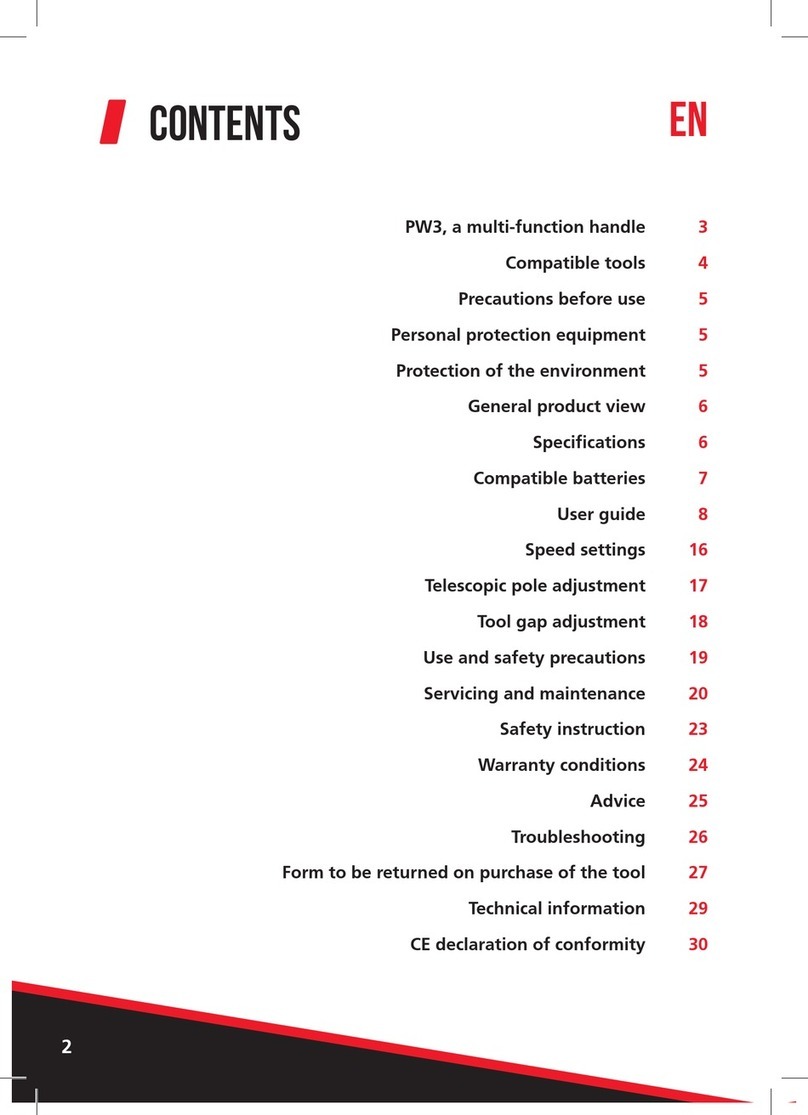
Rockler Power Tool Mobile Base User manual
Other Rockler Power Tools Accessories manuals

Rockler
Rockler 59032 User manual

Rockler
Rockler Pro Lift User manual
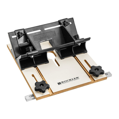
Rockler
Rockler Router Table Spline Jig User manual

Rockler
Rockler 57510 User manual

Rockler
Rockler 57896 User manual

Rockler
Rockler ProFence 47905 User manual

Rockler
Rockler Dust RIGHT User manual

Rockler
Rockler 3/8 Tenon Router Bit User manual
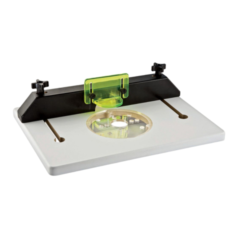
Rockler
Rockler Trim Router Table User manual

Rockler
Rockler 52885 User manual
Popular Power Tools Accessories manuals by other brands

STEINEL PROFESSIONAL
STEINEL PROFESSIONAL 4007841009595 quick start guide
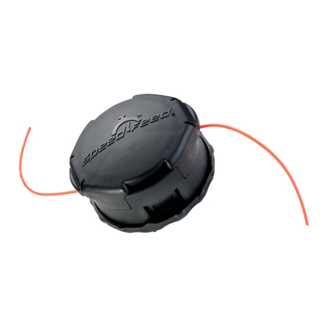
Echo
Echo Speed-Feed Universal 400 LH/RH Installation and loading instructions

SCHUNK
SCHUNK ROTA TB-TBS-EP Assembly and operating manual

Schmid
Schmid RAPID Secure XL Operation instructions
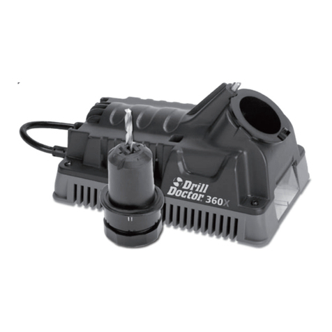
Drill Master
Drill Master 360X user guide
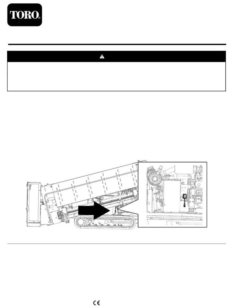
Toro
Toro 138-5050 installation instructions

