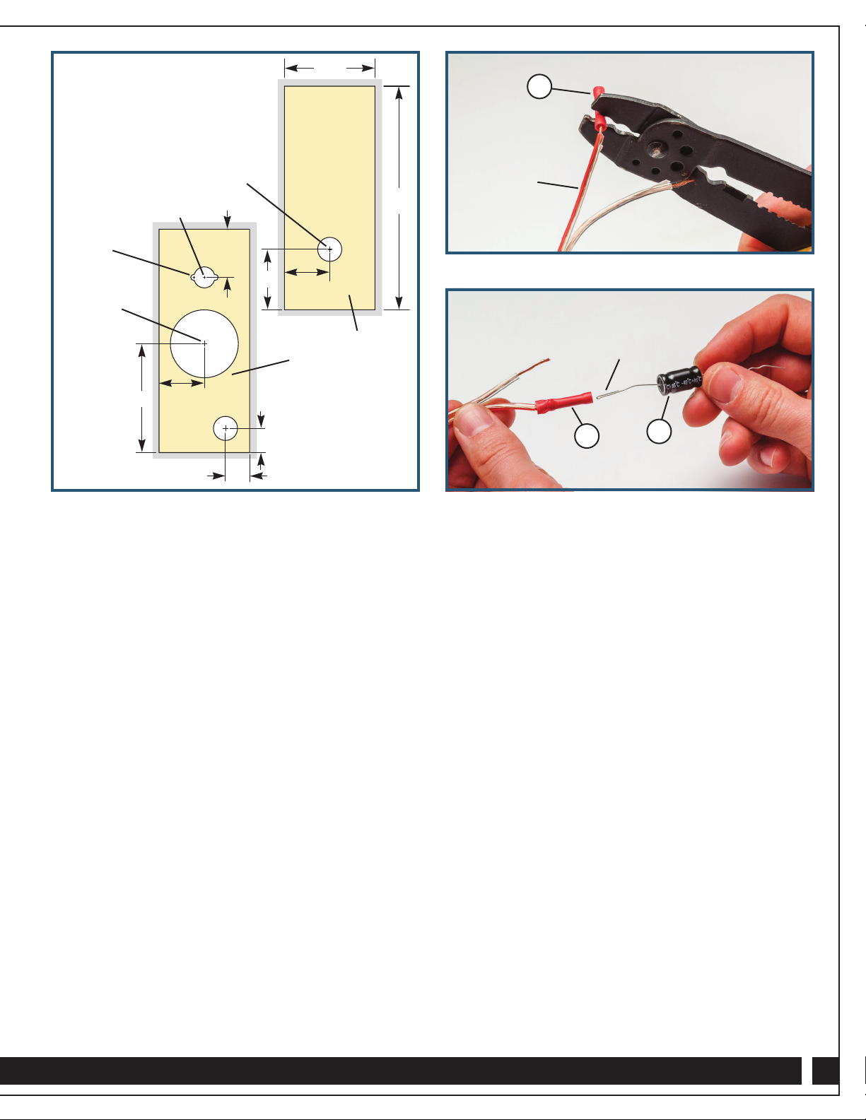
manuals.online logo
Brands
  1. Home
  2. •
  3. Brands
  4. •
  5. Rockler
  6. •
  7. Speakers
  8. •
  9. Rockler 59624 User manual

Rockler 59624 User manual

Other Rockler Speakers manuals

Rockler 66992 User manual

Rockler

Rockler 66992 User manual

Rockler 57033 User manual

Rockler

Rockler 57033 User manual

Rockler 59255 User manual

Rockler

Rockler 59255 User manual

Rockler Wireless Speaker Kit User manual

Rockler

Rockler Wireless Speaker Kit User manual

Rockler 66992 User manual

Rockler

Rockler 66992 User manual

Popular Speakers manuals by other brands

Electro-Voice LR4S engineering data

Electro-Voice

Electro-Voice LR4S engineering data

Definitive Technology Sound Cylinder user guide

Definitive Technology

Definitive Technology Sound Cylinder user guide

AudioSource LS545 user manual

AudioSource

AudioSource LS545 user manual

Paso C402-T Instructions for use

Paso

Paso C402-T Instructions for use

Altec Lansing 416-8C LF SPEAKER manual

Altec Lansing

Altec Lansing 416-8C LF SPEAKER manual

Kenwood KFC-1072 Servise manual

Kenwood

Kenwood KFC-1072 Servise manual

Peavey ProSys 112 user guide

Peavey

Peavey ProSys 112 user guide

JBL Control Contractor 60 Series installation instructions

JBL

JBL Control Contractor 60 Series installation instructions

Aura STORM-8 owner's manual

Aura

Aura STORM-8 owner's manual

Oontz ANGLE 3 PLUS quick start guide

Oontz

Oontz ANGLE 3 PLUS quick start guide

Electro-Voice LR4A engineering data

Electro-Voice

Electro-Voice LR4A engineering data

Rave RK-650-ICA-B owner's manual

Rave

Rave RK-650-ICA-B owner's manual

Flux Reference Series installation manual

Flux

Flux Reference Series installation manual

Lanzar AQAWBS64BK installation manual

Lanzar

Lanzar AQAWBS64BK installation manual

DAPAudio DCS-6230 manual

DAPAudio

DAPAudio DCS-6230 manual

Aluratek ABS03F quick start guide

Aluratek

Aluratek ABS03F quick start guide

Kenwood KES-5A instruction manual

Kenwood

Kenwood KES-5A instruction manual

Sonance ORIGINAL SERIES instruction manual

Sonance

Sonance ORIGINAL SERIES instruction manual

manuals.online logo
manuals.online logoBrands
  • About & Mission
  • Contact us
  • Privacy Policy
  • Terms and Conditions

Copyright 2025 Manuals.Online. All Rights Reserved.

61⁄2" Bookshelf Speaker
Kit Instructions
Congratulations on the purchase of your new 61⁄2" Bookshelf Speaker Kit! It contains the audio
components necessary to wire two speakers. Just build your own custom speaker boxes and enjoy
quality sound! Please read these instructions fully before building your boxes or wiring your speakers.
2
Make Speaker Boxes
1. Build your speaker boxes out of MDF, particleboard,
hardwood plywood or solid wood. For 3/4"material, the
outside dimensions of the box should be
20" H x 9" W x 11" D. Whatever the thickness
of your material, the interior dimensions of the
speaker box should be 181⁄2"H x 71⁄2"W x 91⁄2"D.
2. For each box, follow the Drilling Diagram carefully
to locate and cut the openings for the Woofer (1),
Tweeter (2), Terminal Cup (3) and Air Tube (10).
3. Apply the finish of your choice.
4. Using the Woofers (1), Tweeters(2) and Terminal
Cups (3) as guides in their holes, mark and drill pilot
holes for the #6 x 5/8" Mounting Screws (9). (Use a
3/32" bit for hardwood and a 1/16" bit for softwoods.)
5. Divide the Poly Fill (11) and secure half to the inside
back face of each speaker box with glue or another
adhesive. Spread the fill to avoid obstructing the
openings in the back of the box.
Quantity
1 61⁄2" USA Woofer 2
2 1" Silk Dome Tweeter 2
3 Terminal Cup 2
4 6' Speaker Wire 2
5 Capacitor 2
6 Butt Connector 2
7 Small Terminal Clip 2
8 Large Terminal Clip 10
9 #6x5/8" Mounting
Screws (Not Shown) 22
10 Air Tube 2
11 Poly Fill 1
PARTS LIST - 61⁄2" BOOKCASE SPEAKER KIT
11
11
3 24
5
7
8 6
2
10 10
Drilling Diagram
3
Wiring the Speakers
Note: To ensure strong connections, we recommend using
a crimping tool where wires feed into the Terminal Clips (7
and 8) and Butt Connector (6). Fig. 1.
1. Cut the 6' Speaker Wire (4) into four equal sections
and split the ends.
2. Using electrician’s pliers or a wire stripper, remove about
1/2" of the plastic sheath at the ends of the wires.
3. For each speaker, carefully follow the Wiring Diagram
on Page 4 to connect one section of Speaker Wire (4) to
the Woofer (1) and one to the Tweeter (2).
A. The red-striped wires should be connected to
positive (+) terminals and the unmarked wires
to negative (-) terminals.
B. To make the connections, you will feed the wires into
Terminal Clips (7 and 8) and use a crimping tool to
join the two. The Terminal Clips (7 and 8) then slide
onto tabs on the speaker components. Use Large
Terminal Clips (8) for both wires to the Woofer (1)
and for the positive wire to the Tweeter (2). Use a
Small Terminal Clip (7) for the negative wire to
the Tweeter (2).
4. Using the #6 x 5/8" screws (9), mount the Woofer (1)
and Tweeter (2) to the speaker box. Feed the wires
through the opening for the Terminal Cup (3) in
the back of the box.
Check Rockler.com for updates. If you have further questions, please
contact our Technical Support Department at 1-800-260-9663
or support@rockler.com
Fig. 2
Fig. 1
5. Insert the positive wire coming from the Tweeter (2)
into one end of the Butt Connector (6) and crimp to join.
Double over the wire at one end of the Capacitor (5),
insert it into the other end of the Butt Connector (6) and
crimp to join. Fig. 2.
6. Carefully following the Wiring Diagram, connect the
wires from the Woofer (1) and Tweeter (2) to the
Terminal Cup (3).
A. Feed the negative wires coming from the Woofer (1)
and Tweeter (2) into a Large Terminal Clip (8) and
crimp to join. Slide the Large Terminal Clip (8) onto
the negative tab on the Terminal Cup (3).
B. Feed the positive wire from the Woofer (1) and the
single wire from the Capacitor (5) into a Large
Terminal Clip (8) and crimp to join. Slide the Large
Terminal Clip (8) onto the positive tab on the
Terminal Cup (3).
7. Using the #6 x 5/8" screws (9), mount the Terminal
Cup (3) to the speaker box.
8. Install the Air Tube (10) in its mounting hole.
65
Looped end
6
71⁄2"
2" Diameter
Note: Hole position
measurements are based
on interior dimensions of
speaker box
181⁄2"
31⁄4"
5"
21⁄4"
31⁄4"
2"
2"
9"
1/2" Diameter
13⁄4" Diameter
55⁄8" Diameter
2" Diameter
Front Panel
Back Panel
Red Stripe
4Distributed by Rockler Companies, Inc.
©2015 Rockler Woodworking and Hardware
59624
Rev 03/15
Black 36" x 68" Speaker Cloth ..17899
Beige 36" x 68" Speaker Cloth..17906
Speaker Panel Connectors .......12500
Speaker Baffle Cover Sheet......31027
Screw-On Case Feet.................18673
CUSTOMIZE YOUR
SPEAKERS FURTHER!
Wiring
Diagram
Negative
terminal is
the smaller
of the 2 ports
Positive terminal
has a red dot to
the right of it
Woofer (1)
Tweeter (2) Terminal Cup (3)
Small
Terminal
Clip (7)
Large
Terminal
Clip (8)
Large
Terminal
Clip (8)
Large
Terminal
Clip (8)
Butt Connector (6)
Capacitor (5)
Large
Terminal
Clip (8)
Large
Terminal
Clip (8)