Rockwell Automation Publication 1606-RM116A-EN-P - September 2020 9
Output The output provides a SELV/PELV rated voltage, which is galvanically isolated
from the input voltage.
The output is designed to supply any kind of loads, including capacitive and
inductive loads. If large capacitors, such as EDLCs (electric double layer
capacitors or “UltraCaps”) with a capacitance > 0.1 F, are connected to the
output, the unit might charge the capacitor in an intermittent mode.
The output is electronically protected against overload, no-load, and short-
circuits. If there is a protection event, audible noise may occur.
Attributes Values Notes
Output voltage Nom 48V
Adjustment range
Min 48…56V Guaranteed value
Max 58.0V This is the maximum output voltage that can occur at the clockwise end position of the potentiometer
due to tolerances. It is not guaranteed that this value can be achieved.
Factory settings Typ 48.0V ±0.2%, at full load and cold unit
Line regulation Max 10 mV Between 85…300V AC
Load regulation Max 50 mV Between 0…3 A, static value, see Figure 9
Ripple and noise voltage Max 50 mVpp Load >0.1 A, Bandwidth 20 Hz…20 MHz, 50 Ω
Max 300 mVpp Load <0.1 A, Bandwidth 20 Hz…20 MHz, 50 Ω
Output current
Nom 3 A(1) At 48V and ambient temperature below 45 °C (113 °F)
Nom 2.5 A At 48V and 60 °C (140 °F) ambient temperature
Nom 1.9 A At 48V and 70 °C (158 °F) ambient temperature
Nom 2.6 A(1) At 56V and ambient temperature below 45 °C (113 °F)
Nom 2.1 A At 56V and 60 °C (140 °F) ambient temperature
Nom 1.6 A At 56V and 70 °C (158 °F) ambient temperature
— Derate linearly between 45…70 °C (113…158 °F)
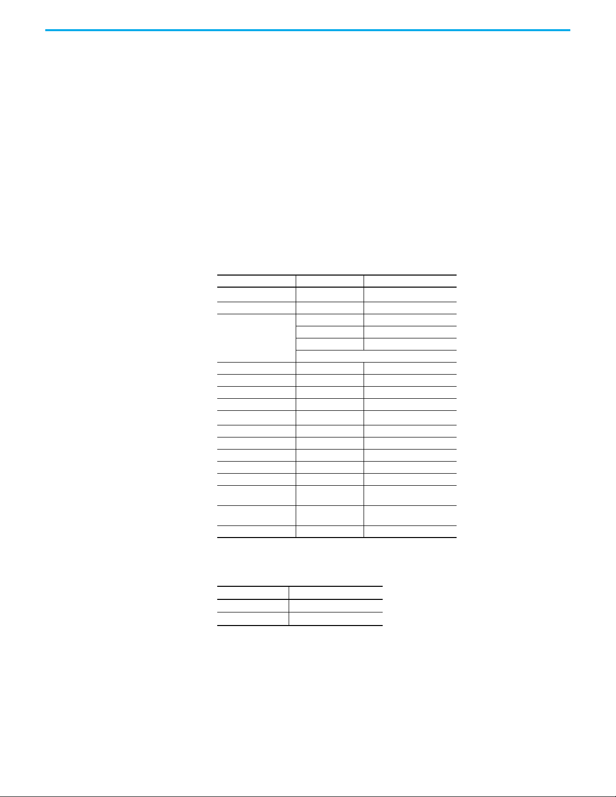
Fuse breaking current Typ 7.5 A Up to 12 ms once every 5 seconds, see Figure 10. The fuse breaking current is an enhanced transient
current that helps to trip fuses on faulty output branches. The output voltage stays above 40V.
Overload behavior
—Continuous
current For output voltage above 26V DC, see Figure 9
—Intermittent
current(2) For output voltage below 26V DC, see Figure 9
Overload/ short-circuit
current
Max 3.4 A Continuous current, see Figure 9
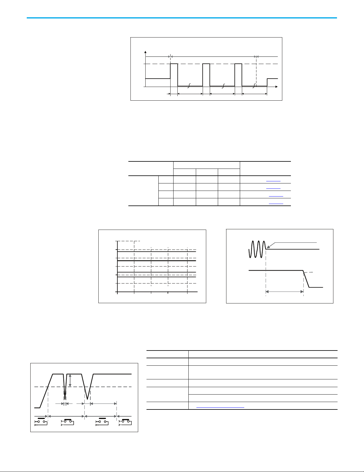
Typ 5 A Intermitted current peak value for 1 s typ. Load impedance 50 mΩ, see Figure 11 on page 10. Discharge
current of output capacitors is not included.
Max 1.5 A Intermitted current average value (R.M.S.). Load impedance 50 mΩ, see Figure 11 on page 10.
Output capacitance Typ 750 μF Included inside the power supply
Back-feeding loads Max 63V The unit is resistant and does not show malfunctioning when a load feeds back voltage to the power
supply. It does not matter whether the power supply is on or off. The absorbing energy can be
calculated according to the built-in large sized output capacitor.
(1) This current is also available for temperatures up to 70 °C (158 °F) with a duty cycle of 10% and/ or not longer than 1 minute every 10 minutes.
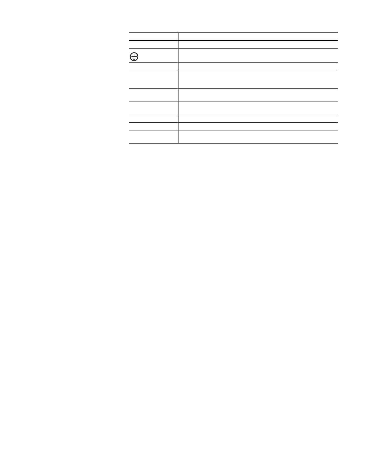
(2) At heavy overloads, the power supply delivers continuous output current for 1 s. After this, the output is switched off for approx 9 s before a new start attempt
is automatically performed. This cycle is repeated as long as the overload exists. If the overload is cleared, the device operates normally. See Figure 11.
Figure 9 - Output Voltage Versus Output Current, Typ Figure 10 - Dynamic Output Current Capability, Typ
Output Voltage
0
30
8
16
24
56V
32
40
48
5 A20.5 1 2.5 3.5 41.5 4.5
Adjustment
Range
Output Current
A: continuous current
B: intermittent current
A
B
Output Voltage
(dynamic behavior, < 12 ms)
0
0
8
16
24
56V
32
40
48
10 A426813579
Adjustment
Range
Output Current