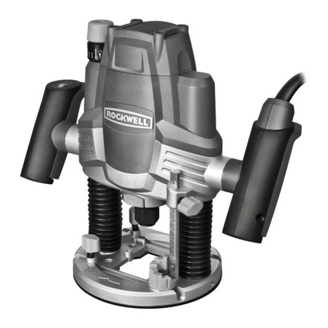
ROUTER EN
9
TECHNICAL DATA
OPERATING INSTRUCTIONS
NOTE: Before using the tool, read the instruction
book carefully.
1. SETTING THE DEPTH STOP (See Fig.A)
a) Loosen the xing screw and adjust the depth stop
upward or downward. Note the position of the
scale on the body and raise the depth stop by the
required amount. Each mark on the scale is equal
to 1mm.
b) Tighten the depth stop xing screw.
NOTE: If you want to make some accurate adjustment,
micro- adjustment can be made by turning the ne
adjustment knob. A full turn is equal to 1mm.
2. FITTING THE VACUUM ADAPTOR (See Fig.B)
For the safe of your health and working environment,
always use a vacuum adaptor.
Use the two long screws to fasten the adaptor socket
securely to the routing base. The adaptor socket is
suitable for vacuum adapter with a suction hose.
3. FITTING THE ROUTER BIT (See Fig.C,D)
• Press in the spindle lock button, loosen the collet
nut with a spanner anti-clockwise and insert the
required router bit. (See Fig. C)
Make sure the spring and collet nut are inside
before inserting the bits and that the bit ts the
collet nut.
• Press in the spindle lock and tighten the collet nut
with a spanner clockwise, making sure at least
3mm protrudes from the end of the shank. (See
Fig. D)
NOTE: Wait until the machine complete stops before
press the spindle lock.
4. ADJUSTING DEPTH OF CUT
The depth of cut is the distance between the step
buffer and the depth stop bar.
Router bits vary in depth, the step buffer allows
for this with its six positions. Use one of the two
following methods:
Method 1: Using a piece of wood method (See
Fig.E,F,G)
Fit the router bit, loosen the depth stop bar xing
screw, pull the plunge lock lever (See Fig. E) up
and plunge the router down until the bit comes into
contact with the workpiece.
Lock the router into this position by pushing down the
plunge lock lever.
Lift up the depth stop bar (See Fig. F) and insert a
piece of wood the same thickness as the depth of cut
between the stop bar and step buffer. (See Fig. G)
Tighten the depth stop bar xing screw and release
the plunge lock lever to return the router back to its
original position. The depth of cut is now set, see
“Starting the router” section for nal operation.
Method 2: Using the scale method
Fit the router bit, loosen the depth stop bar xing
screw and release the plunge lock lever.
Lower the router down until it contacts the workpiece,
lock into this position with the plunge lock lever.
The scale on the depth bar now shows the starting
position. Note the starting position will vary
depending on the bit used.
Next add the required depth of the cut to the starting
position, i.e.: if the scale shows 20mm and you
require a cut of 10mm, then the correct adjustment on
the scale is 20+10=30mm, if the scale shows 38mm
and the required cut is 6mm in depth, the adjustment
on the scale will be 38+6=44mm.
Now move the depth stop bar to the calculated
number, and lock bar with the xing screw.
Release the plunge lock lever, the router will return to
its original position.
Start Router as described in “Starting the router”
section below.
5. USING THE STEP BUFFER (See Fig.I)
For deep cuts, it is recommended to carry out several
cuts, each with less material removal. By using the
step buffer, the cutting process can be divided into
several steps.
6. FINE ADJUSTMENT TO CUT DEPTH (See Fig.H,I)
Rotating the ne adjustment knob allows extremely
precise adjustment of the bit depth. One complete
revolution equals 1mm. It should be adjusted only
Voltage
Rated power
No load speed
Max. plunge depth
Collet sizes
Protection class
Machine weight
230-240V~50Hz
1500W
11000-26000/min
50mm
6.35mm/12mm
/II
4.75kg
