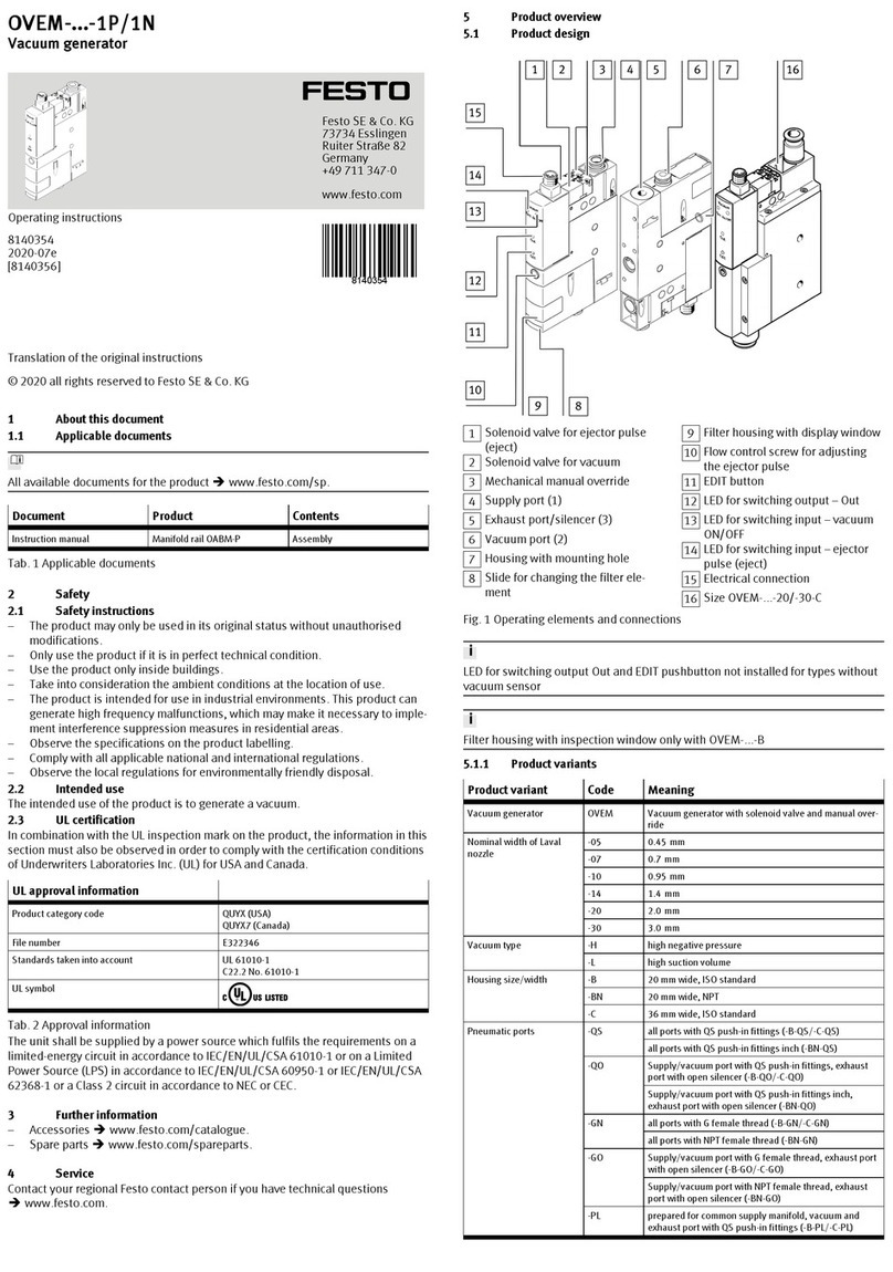
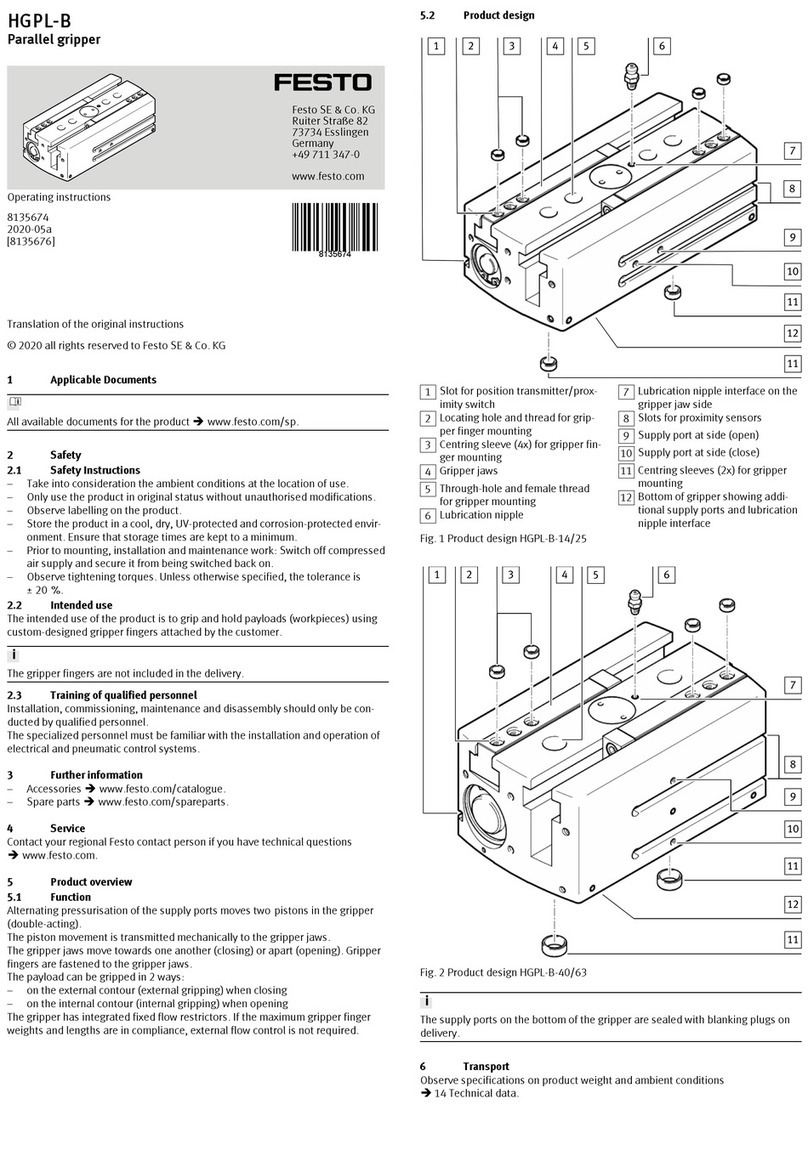
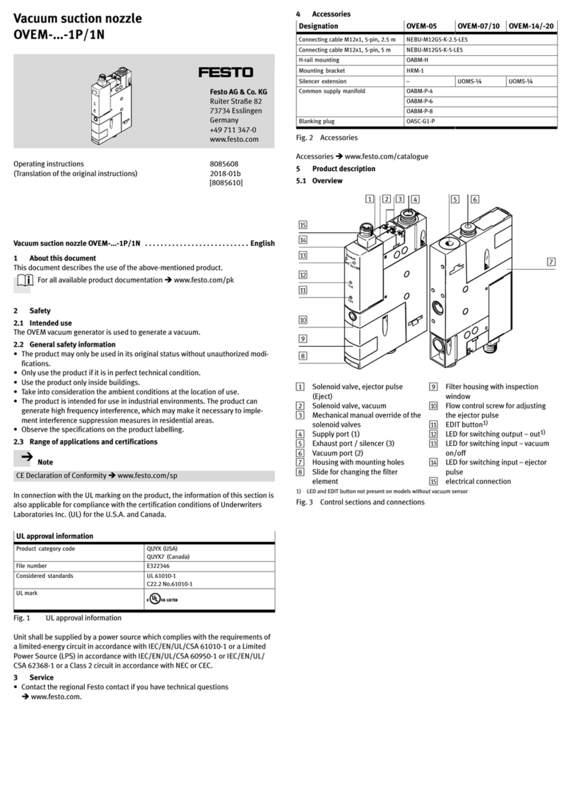
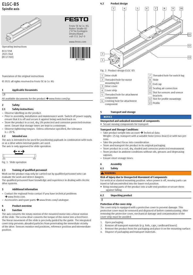
Festo VPPE-3-1-1/8 E1 Series User manual

Translation of the original instructions
© 2021 all rights reserved to Festo SE & Co. KG
1 Applicable Documents
All available documents for the product èwww.festo.com/sp.
2 Safety
2.1 Safety instructions
– Only use the product in original status without unauthorised modifications.
– Only use the product if it is in perfect technical condition.
– Take into consideration the ambient conditions at the location of use.
– Before working on the product, switch off the power supply and secure it
against being switched on again.
2.2 Intended use
The proportional-pressure regulator is intended to regulate a pressure propor-
tional to a specified setpoint value. The product is intended for use in industrial
environments.
2.3 Training of qualified personnel
Work on the product may only be carried out by qualified personnel who can eval-
uate the work and detect dangers. The qualified personnel have skills and experi-
ence in dealing with electropneumatic (open-loop) control technology.
2.4 Approvals
In combination with the UL inspection mark on the product, the information in this
section must also be observed in order to comply with the certification conditions
of Underwriters Laboratories Inc. (UL) for USA and Canada.
UL certification information
Product category code QUYX, QUYX7
File number E322346
Considered standards UL 610101, CAN/CSAC22.2 No. 61010-1
UL mark
Tab. 1
• The unit shall be supplied by a power source which fulfils the requirements
on a limited-energy circuit in accordance to IEC/EN/UL/CSA 61010-1 or on a
Limited Power Source (LPS) in accordance to IEC/EN/UL/CSA 60950-1 or
IEC/EN/UL/CSA 62368-1 or a Class 2 circuit in accordance to NEC or CEC.
Electrical data and ambient conditions
Supply voltage 24 V DC
Max. power 4.2 W
Rated pressure up to 1.1 MPa
Max. installation height 2000 m
Tab. 2
3 Further information
– Accessories èwww.festo.com/catalogue.
– Spare parts èwww.festo.com/spareparts.
4 Service
Contact your regional Festo contact person if you have technical questions
èwww.festo.com.
4.1 Function
4.1.1 Functional principle
The VPPE-... is intended for regulating pressure proportionally to a specified set-
point value. Manually adjustable pressure regulators can be replaced by remotely
adjustable electric closed-loop controllers. Thisallows various machine paramet-
ers to be available quickly and automatically.
Fig. 1
4.2 Configuration
4.2.1 Product design
1Side mounting hole
2Input supply port
3LED display
4Electrical connection
5Status LED
6Earth terminal, external (front and
back)
7Up arrow button
8Down arrow button
9EDIT button
10 Output supply port
11 Exhaust supply port
12 Front mounting hole
Fig. 2 Product design VPPE-...-E1
1Side mounting hole
2Input supply port
3Earth terminal, external (front and
back)
4Electrical connection
5Up arrow button
6LED display
7Status LED
8Down arrow button
9EDIT button
10 Output supply port
11 Exhaust supply port
12 Front mounting hole
Fig. 3 Product design VPPE-...-E1T
8136809
VPPE-3-1-1/8-...-E1
Proportional-pressure regulator
8136809
2021-01e
[8136811]
Operating instructions
Festo SE & Co. KG
Ruiter Straße 82
73734 Esslingen
Germany
+49 711 347-0
www.festo.com

5 Mounting
1. Place the VPPE-... as close to the consumer as possible. This improves control
precision and reduces response times.
2. Push two screws (M4) into the holes for lateral mounting è Fig.2, 1 or the
holes for front mounting è Fig.2, aB, max. tightening torque: 2Nm.
3. Mount the VPPE-... in the intended position.
NOTICE!
• When installing the VPPE-…-E1T on the mounting rail IPM-PN-08-40x80-AL,
note that the compressed air supply corresponds to the total air consump-
tion. For more information see the assembly instructions for the VAME-PS-
MK.
6 Installation
6.1 Pneumatic installation
1. Remove the covers from the supply ports.
2. Attach the tubing to the following ports (è Fig.2):
Input supply port (1), position 2
Output supply port (2), position aJ
3. Mount a silencer at the exhaust supply port (3) (position aA) or extract the
exhaust air using ducts.
Operating medium
NOTICE!
Too much residual oil content in the compressed air will reduce the service life of
the valve.
• When using organic oils (oils that are based on synthetic esters or native
esters, e.g.rapeseed oil methyl ester), the maximum residual oil content of
0.1mg/m³ must not be exceeded (è Compressed air to ISO 8573-1:2010
[–:–:2]).
The position of the pneumatic ports depends on the variant ordered.
6.2 Electrical installation
WARNING!
Risk of injury due to electric shock.
• For the electrical power supply, use only PELV circuits in accordance with IEC
60204-1/EN 60204-1 (Protective Extra-Low Voltage, PELV).
• Observe the general requirements of IEC 60204-1/EN60204-1 for PELV cir-
cuits.
• Only use voltage sources that ensure a reliable electric separation from the
mains network in accordance with IEC 60204-1/EN 60204-1.
• Use the following connection accessories (è 3 Further information):
– plug socket with cable or
– plug socket cable, pre-assembled.
This ensures that the specified degree of protection IP65 and EMC is achieved.
NOTICE!
To guarantee EMC safety, the device must be earthed as follows:
• Use the earth terminal (è Fig.2, è Fig.3).
• Use the following earthing accessories (included in the scope of delivery):
– Self-tapping screw
– Flat plug
– Contact washer.
• Wire the VPPE-... in accordance with the plug pattern. Preferably use Festo
cables.
Pin Colour 1) Allocation
1 brown +24VDC
2 white Analogue input - setpoint value/-w
3 blue GND
4 black Analogue input - setpoint value/+w
(0…10V or 4…20mA)
5 grey Switching output (24 V) or
Analogue output (0…10V or 4…20 mA)
Actual value/XOUT
1) Colour is only valid for Festo accessory cables
Tab. 3 Pin allocation M12x1 plug, 5-pin
7 Commissioning
NOTICE!
• The VPPE-... interprets setpoint signals less than 0.1 V as 0 V and setpoint sig-
nals less than 4.16 mA as 4 mA. In this case, the output pressure is set to 0
MPa by activation of the exhaust valve. As a result, a defined valve condition
is assured at w = 0.
• Safety position: if the voltage variant setpoint value cable breaks, the output
pressure is set to 0 MPa. If the current variant cable breaks or if the supply
voltage fails, the output pressure is maintained uncontrolled. Leakage results
in a change of pressure over the long term.
1. Connect the VPPE-... with a setpoint value signal. The VPPE has a so-called
“differential input”. The setpoint signal is applied to the contact pin 2 and pin
4, where the lower potential must be connected to the contact pin 2 and the
higher potential to the contact pin 4.
Contact pin 2 (– setpoint value) can be connected to contact pin 3 (GND).
2. Energise the VPPE-... with direct current (supply voltage UV = 24 V DC ± 10%).
3. Pressurise the VPPE-... to at least 0.1MPa higher input pressure (p1) than the
maximum desired output pressure. This sets proportional output pressure
(p2).
The following output pressure range is then allocated to the setpoint value signal
range 0…10V or 4…20mA:
Output pressure range of the variantSetpoint value
signal range 0.2 MPa 0.6 MPa 1 MPa
0…10V or
4…20mA
0.002…0.2 MPa 0.006…0.6 MPa 0.01…1 MPa
Tab. 4 Setpoint value signal range and associated output pressure range
7.1 Recommended parameter sets
The valves in all pressure variants are set at the factory to Preset 2.
PresetPreset recommendation
123
Consumer volume < 0.5 l ~ 0.5 l > 0.5 l
Tab. 5 Recommended parameter sets
7.2 VPPE display and meaning
In the delivery status the display corresponds to the factory setting
è 10.1 Reset to factory settings.
Display Meaning Description
[An] Analogue Output: analogue
[bAr] bar Pressure unit
[Eco] ECO mode Display shutdown (adjustable)
[Frc] Force Manual setpoint specification
[HY] Hysteresis Spread, switch difference
[in] Setpoint value When the v button is pressed (1 sec.), [in]
appears. The setpoint value is displayed when
the button is released.
[Loc] Lock Input locked with PIN code
[n.Hi] Switch normally closed N/C contact (normally closed)
[n.Lo] Switch normally open N/O contact (normally open)
[OFS] Offset Zero point increase
(Outlet pressure without setpoint value)
[out] Actual value When the v button is pressed (1 sec.), [out]
appears. The actual value is displayed when the
button is released.
[PA] Kilopascal Pressure unit (in kPa!)
[Pin] Pin code Enter value for locking
(1…999)
[Pr1] Preset 1 (è 7.1 Recommended parameter sets
[Pr2] Preset 2 (è 7.1 Recommended parameter sets
[Pr3] Preset 3 (è 7.1 Recommended parameter sets
[PSi] psi Pressure unit
[rES] Reset
(factory setting)
Switch on device while pressing V + v + Edit
buttons. Observe note in section
è 10.1 Reset to factory settings.
[rnG] Range Pressure range adjustment
[Snr] Display serial number Switch on device while pressing v + Edit but-
tons: 6-digit serial number is displayed, first
[xxx.] then [xxx] alternating approx. every 2 sec.
[SOF] Display software version Switch on device while pressing V + Edit keys:
software version appears
[SP] Switching point è 6.2 Electrical installation
[SP.H] Switching Point high Upper switching point
è 6.2 Electrical installation
[SP.L] Switching Point low Lower switching point
è 6.2 Electrical installation
[SP.O.] Set Point ok Setpoint value reached
è 6.2 Electrical installation
[unL] Unlock Lock removed
Threshold value comparator è 6.2 Electrical installation
Window comparator è 6.2 Electrical installation
[._..] ECO mode activated A line moves through the display [._..] after x
seconds (adjustable)
Tab. 6 Indication on display
7.3 Configuring the output
– The display of the actual value at the analogue output [An] is 0…10V or
4…20mA depending on the ordered variant.
– If a switching output is selected, the following modes can be selected:
threshold value, window comparator or SP.O.
Switching points (SP...) and hysteresis (HY)
The switching point is only active when a threshold value or window comparator
is selected.
The value of the hysteresis specifies the tolerance for the deviation before a sig-
nal change occurs at the output (Pin 5).
Setting SP.O.
The SP.O. signal indicates that the setpoint value has been reached in the range
(+/-) of the set hysteresis.
If the threshold value comparator is set
Switching characteristic NO (normally open)
Switching characteristic NC (normally closed)
Tab. 7 Window comparator
If SP.O. is selected
1Hysteresis
2Setpoint value
3Actual value
4SP.O. signal
Fig. 4 If SP.O. is selected
7.4 Display symbols menu
Notes on the following table:
[x.xx] = pressure indicator (actual value or setpoint value)
[ ... ] = input value (with flashing display)
– The main menu selection can be made in only one direction with the Selection
button V.
– Within a menu option the selection can generally be made with the v or V
button.
– If no selection is made within 10 sec. in the main menu or 80 sec. within a
menu option, the display automatically jumps back to the initial position,
which is exception [Frc].
Menu = main menu selection
[x.xx] = value specification (setpoint value/actual value)
Continue in the menu = press Edit button
If the display flashes (grey background) = you can make a selection with v V
buttons
Change value [ ... ] = with v V buttons
Save selection/value = press Edit button
No. Menu Selection option v V
1 [x.xx] v (1 sec.) = [in] V (1 sec.) = [out]
2 [Pr...]
[Pr...] Pr1 Pr2 Pr3
3 [bAr]
[bAr] bAr PA PSI
4 [OFS]
[ ... ]
5 [rnG]
[ ... ]
6 [Frc] 0.00…10.0 V (voltage variant)
4.00…20.0 mA (current variant)
[ ... ]
7 [An]
[An] SP.O.
SP SP.L HY
[ ... ] [ ... ] [ ... ]
[ ... ] [ ... ] [ ... ]
HY SP.H [n.Lo/n.Hi]
[ ... ] [ ... ] [n.Lo/n.Hi]
[ ... ] [ ... ]
[n.Lo/n.Hi] HY
[n.Lo/n.Hi] [ ... ]
[ ... ]
n.Lo/n.Hi
n.Lo/n.Hi
8 [Eco]
[OFF]
[OFF] [1…999] sec.
9 [Pin]
[OFF]
[OFF] [1…999]
back
to no. 1
Tab. 8
7.5 Preparation
8 Operation
NOTICE!
When switching off the VPPE-..., make sure that the setpoint voltage or setpoint
current intensity is switched off first, then switch off the supply pressure and
finally the supply voltage.
The green status LED lights if the actual value is equal to the setpoint value of
within a range of ± 1% (FS) of the setpoint value.
Lock [Loc] - unlock [unL]
If a PIN code was entered with [Pin], [Loc] is shown in the display and the edit
mode is locked via the PIN code. If a flashing [0] appears, enter the correct pin.
After the correct PIN is entered, [unL] is displayed. If the input is incorrect, the
VPPE returns to the initial position.
9 Maintenance
– Clean the housing of the VPPE-... with a soft cloth only. The permitted clean-
ing medium is a mild detergent solution at max. 50°C.
10 Malfunctions
Malfunction Possible cause Remedy
No supply voltage, LED not on Check the connection of the 24 VDC
supply voltage
No setpoint voltage Check the controller and connection
VPPE -...
does not react
VPPE-... fault Send the device to the Festo repair
service
Flow rate too low Restriction of the flow cross section
due to connection technology (swivel
fittings)
Use alternative connections
Pressure rise too
slow
Large cylinder volume and long tube
length
Select different parameter set
Supply cable breakage (the last output
pressure set is maintained but not reg-
ulated). Slow pressure drop due to
leakage.
Replace supply cablePressure constant
despite modified
setpoint specifica-
tion
Supply pressure p1 too low Increase supply pressure
Tab. 9

10.1 Reset to factory settings
NOTICE!
Resetting to the factory settings will lose the current settings.
• If required, make a note of these settings before reset.
Reset [rES] restores the factory setting. Press and hold "v + V + Edit" and then
switch on the device.
The following parameters are then set:
Parameter Setting/value
x.xx Permanent display (actual value/setpoint value)
Pr2 (universal control behaviour)
bar bar
OFS 000
rnG for 1 MPa type: 10
for 0.6 MPa type: 6
for 0.2 MPa type: 2
Frc Display shows existing pressure at pressure output (p2)
An Output: analogue
Eco OFF
Pin OFF
Tab. 10
10.2 Repair
Send the product to the Festo repair service for repair.
11 Technical data
Fig. 5 VPPE-3-1-1/8-2-... p1 = 0.4 MPa
Fig. 6 VPPE-3-1-1/8-6-... p1 = 0.8 MPa
Fig. 7 VPPE-3-1-1/8-10-... p1 = 1.1 MPa
Characteristic values
Design Proportional-pressure regulator
Characteristic values
Mounting position As desired, preferably vertical (electronics upward).
Medium [7:4:4]
Lubricated operation not possible
Pressure regulation range [MPa] 0.002…0.2 0.006…0.6 0.01…1
Permissible input pressure
(Input pressure p1 min. 0.1
MPa above output pressure
p2)
[MPa] 0.3…0.4 0.6…0.8 0.6…1.1
Standard nominal flow rate è Fig.5 to è Fig.7
Total leakage when new [l/h] < 5
Ports G1/8
Nominal width
Pressurisation [mm] 5
Exhaust [mm] 2.5
Degree of protection IP 65 in combination with connector socket according to
accessories
Permissible temperature range
Environment [°C] 0…+60
Storage [°C] –10…+60
Medium [°C] +10…+50
Electrical connection Pin contact M12x1, 5-pin
Permitted supply voltage 24 VDC ± 10%
Setpoint variable input resistance 0…+10 V/4…20 mA
10 kΩ (voltage)/250 Ω (current)
Load actual value output min. 2 kΩ (voltage)
max. 500 Ω (current)
Residual ripple [%] 10
Vibration and shock
Vibration Tested in accordance with DIN/IEC 68/EN 60068
Part 2-6,
Severity level 2
Shock Tested in accordance with DIN/IEC 68/EN 60068
Part 2-27,
Severity level 2
Power consumption [W] max. 4.2
Electromagnetic compatibility
– EMC interference emission
and immunity to interfer-
ence
See declaration of conformity
èwww.festo.com
CE conformity for industrial installations fulfilled
Materials
Housing Al
Cover PA
Seals NBR
Lubrication silicone-free
Weight [g] 390
Tab. 11 Characteristic values
Control characteristics
Linearity 1% full scale (FS) at 24 V DC and 25°C
Hysteresis
Pressure regulation range
0.002MPa…0.2MPa
1% full scale (FS)
Pressure regulation range
0.006MPa…0.6MPa
0.5% full scale (FS)
Pressure regulation range
0.01MPa…1MPa
0.5% full scale (FS)
Reproducibility 0.5% full scale (FS)
Total accuracy
Pressure regulation range
0.002MPa…0.2MPa
1.5% full scale (FS)
Pressure regulation range
0.006MPa…0.6MPa
1.25% full scale (FS)
Pressure regulation range
0.01MPa…1MPa
1.25% full scale (FS)
Temperature coefficient 0.04%/K
Tab. 12 Control characteristics
Other Festo Industrial Equipment manuals

Festo
Festo DGEA Series User manual

Festo
Festo Belt Drives 2 Instructions for use

Festo
Festo DNCKE S Series User manual

Festo
Festo EPCO Series User manual

Festo
Festo MPS PA User manual

Festo
Festo EGC Series User manual

Festo
Festo 152962 User manual

Festo
Festo CRDSNU Series Setup guide

Festo
Festo YSR Series User manual

Festo
Festo CPX-FB37 User manual

Festo
Festo P.BE-CPX-MMI-1 Series Parts list manual

Festo
Festo KSK Series User manual

Festo
Festo FLSM Series User manual

Festo
Festo MPS 8046325 User manual

Festo
Festo YXC Series User manual

Festo
Festo EGSL User manual

Festo
Festo MPS Station User manual

Festo
Festo DZF Setup guide

Festo
Festo EduTrainer 8040011 User manual

Festo
Festo ELGC-TB-KF Parts list manual